Branch piercing clamps, or as they are colloquially called SIP nuts, are the most important element of an electrical transmission line made of insulated wires.
The reliability of your power supply and trouble-free operation of the entire VLI depend on them. The contact in them must be constant and, most importantly, reliable throughout the entire service life of the power line, which is 40 years or more. If somewhere they use homemade hooks for hanging a line and this may not affect its reliability for years, then the connection of SIP wires and cables, SIP and SIP, should only be factory-made.
The two most common types of punctures are waterproof and sealed. All manufacturers have recently opted for sealed ones to modernize and develop their line.
In piercing clamps, contact is ensured by plates with pyramidal teeth and a calibrated breakaway head. The moment of failure varies from 9 to 20 Newton, depending on the brand of “nut” and the cross-section of the connected wires.
Two characteristics must be indicated on the body of each clamp - the cross-section of the main line and the cross-section of the branch. Moreover, these parameters can be in a wide range.
For example, sealed clamp SLIW54 16-120/6-50. The first inscription means a line from 16mm2 to 120mm2 inclusive. The second is the cross-section of the seal cable or SIP, which can be connected through this puncture. When choosing, it is better to buy nuts closest to the larger cross-sections of the wire to be connected in order to ensure better transition contact.
Most of these clamps can be used to connect a cable to a live SIP, since the stripping head and the bolt inside do not come into contact with the contact plate.
All clamps except the breakaway clamp have a second head, but it is only necessary for dismantling. Remember that all these punctures are considered one-time use. Do not confuse them with simple die clamps, which can be unscrewed and tightened at least a hundred times.
There are times when electricians try to reuse piercing clamps on the same or a different line. Although the first head is broken, they use the second one to tighten it.
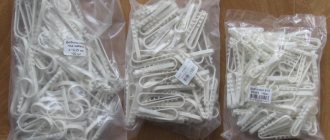
Besides the fact that it is impossible to calculate the exact tightening torque without a torque wrench, for some reason everyone forgets about the deformation of the contact plate teeth after the first puncture. In the photo below, on the right are the teeth after a SIP puncture, on the left - without a puncture. Feel what is called the difference.
Their sharpness is no longer the same, and accordingly, some of them can simply crush the insulation rather than pass through it.
Therefore, according to technology, wherever there are piercing teeth, all these clamps are considered disposable!
So that manufacturers don’t advertise or talk. Precisely because of the teeth, and not because of the nut breaking.
Technical characteristics and brands of piercing clamps from the most famous manufacturers of SIP fittings:
Self-supporting insulated wire (SIP) has recently become the most popular cable product for installing electrification networks of private houses, cottages and other real estate. Before its appearance on the market, various types of insulated or non-insulated wires and cables were mainly used to create overhead power lines, which had a number of significant disadvantages. SIP is completely devoid of all these disadvantages, which is why its popularity is so high. But the method of connecting a self-supporting wire to each other and to other types of cable is not always clear to the average user!
In the process of electrifying private houses, cottages and other buildings, the question always arises of how to connect self-supporting insulated wires with copper cable, other types of wires, and also with each other. The reliability and performance of the entire electrical network of the facility depends on this operation. Failure to comply with installation rules can lead not only to loss of contact between individual parts of the building's energy supply system, but also to more serious negative consequences.
SIP wires are made of aluminum. This metal is subject to rapid oxidation in air and a film with high resistance to electric current is formed on its surface.
Copper conductors do not have such a negative property, so their direct connection with aluminum conductors can lead to loss of functionality of the entire cable line. In this article we will consider the following issues: connection and installation of SIP wires with different types of cable products, as well as their connection to each other.
Scope of application of piercing clamps and their characteristics
These devices allow you to quickly connect to the main line, while ensuring the necessary connection conditions. A characteristic feature of such clamps is that during the installation process there is no need to remove the insulation from the SIP, which significantly speeds up the process and makes it as safe as possible.
Connection using a waterproof clamp of SIP wires
The main area of application of these devices is supplying power to the consumer's distribution panel, for example, connecting a house or garage to the main trunk line. The clamp body is made of durable plastic that is resistant to ultraviolet radiation and other harmful environmental influences. The contact point itself is reliably protected from moisture.
Relatively low cost, easy installation and dismantling and full compliance with regulatory requirements have made this connection method almost standard. The barbaric option for connecting to the main line - “twisting” – is now almost never seen.
Twisting is not only an unreliable, but also an unsafe connection method
Types of parts
The industry envisages the production of several types of clamps for SIPs. All of them are designed to work in certain conditions.
Branch piercing with one bolt
This type of clamp is also often called a bare clamp. It is used to lead the wire (uninsulated) to the vulture.
Distinctive features:
- Section from 16 to 95 mm.
- The polymer housing of the clamp can prevent UV rays from penetrating inside and is also resistant to various weather conditions.
- The branch clamp has a stable bar.
In this case, the branch piercing clamp is made of aluminum (alloy), which prevents rust
. Both the bolt and the mechanism are reliably made.
Piercing branch with two bolts
A tap component is used to route bare wires to the main trunk line to the sip line. The cross section can reach 95 square mm. The body uses highly resistant glass-reinforced polymer. For convenience, the branch clamp has a lower bar that helps fix the key in a given position.
This item will last a long time
, since it is resistant to moisture, wind and other manifestations of the external environment. Manufacturers, as a rule, are responsible for quality, so in this case you can count on it.
When choosing a clamp for SIP, it is worth remembering that the bolt head must be proportional to the key. most commonly used head is 13 mm
. Sometimes you can find 17 mm, but much less often. The size of the wire cross-section indicates the thickness of the line. From this size you can understand the size of the branch that should be mounted in the branch clamp. When choosing this part for SIP, you need to remember all these simple rules.
When designing electrical wiring, all issues that relate to running the cable to the input circuit breaker are often ignored, since this point is taken for granted. However, installing a piercing clamp for SIP wires is a very responsible undertaking that requires full mastery of the technology. When conducting wires, you must be guided by two bases - durability and safety.
In addition, it is important that any element or part of the chain can be reached without problems for the purpose of repair or replacement. In this article we will look at the principle of operation, purpose and installation features of a piercing clamp for SIP wires
Principle of operation
A piercing clamp for SIP is a special device that connects two parallel wires. It allows you to provide both parallel and serial connections - in the first case, with the help of a squeeze (as it is also called), a branch from the main wire is organized, in the second, a clamp is used to connect, inserting them into different (required!) sockets, two pieces of wire, and in their bare ends are covered with protective dielectric caps.
The electrical connection is made by piercing the outer insulation of a self-supporting wire with pyramid-shaped teeth, which, when pierced, reliably “seal” the place where they ate into the wire, preventing moisture from entering there.
OZPI
The technology of modern branch clamps with insulation piercing (IPPI) is developing in the following areas:
- improved contact system;
- new materials for the manufacture of clamp bodies;
- controlled tightening force of the main bolt;
- increased tightness of connections;
- increasing ease of installation.
Modernization of contact group
- Plates made of aluminum alloys and with pyramidal-shaped teeth, placed in a checkerboard pattern (Fig. a below).
- Aluminum or copper plates with wedge-shaped teeth like a saw (Fig. b).
- Aluminum plates that combine the advantages of previous types (Fig. c).
OPPI devices from popular manufacturers: a – Ensto; b – (1 – Sicame and Simale, 2 – Niled); c – Sicame and Simale
Any of the three methods guarantees the creation of a puncture of insulation and reliable electrical contact with the current-carrying core of the SIP. The material of the phase wires is softer than the neutral wire and the teeth penetrate deeper into them. In any case, the shear head of the tightening bolt ensures the creation of reliable electrical contact while maintaining the required strength of the conductor.
The housings shown in Fig. The above models are made of glass fiber reinforced polyamide. They have good mechanical and electrical properties and withstand weathering well.
The tightening process of the main bolt is controlled due to the shear head. It provides only one-time use of the OPPI. However, you can use a torque wrench to create the required force. This option was used in early models of devices, but it turned out to be not very convenient.
Using specific torque charts for different models, you can use a torque wrench for secondary installation. In this case, you cannot be completely sure of the reliability of the connections, since the piercing teeth in the clamp used are deformed.
Installers prefer models with minimal tightening force.
Sealed and waterproof piercing clips
The two most common types of punctures are waterproof and sealed. All manufacturers have recently opted for sealed ones to modernize and develop their line.
In piercing clamps, contact is ensured by plates with pyramidal teeth and a calibrated breakaway head. The moment of failure varies from 9 to 20 Newton, depending on the brand of “nut” and the cross-section of the connected wires.
Two characteristics must be indicated on the body of each clamp - the cross-section of the main line and the cross-section of the branch. Moreover, these parameters can be in a wide range. For example, sealed clamp SLIW54 16-120/6-50. The first inscription means a line from 16mm2 to 120mm2 inclusive. The second is the cross-section of the seal cable or SIP, which can be connected through this puncture. When choosing, it is better to buy nuts closest to the larger cross-sections of the wire to be connected in order to ensure better transition contact.
Most of these clamps can be used to connect a cable to a live SIP, since the stripping head and the bolt inside do not come into contact with the contact plate.
All clamps except the breakaway clamp have a second head, but it is only necessary for dismantling. Remember that all these punctures are considered one-time use. Do not confuse them with simple die clamps, which can be unscrewed and tightened at least a hundred times. There are times when electricians try to reuse piercing clamps on the same or a different line. Although the first head is broken, they use the second one to tighten it.
Besides the fact that it is impossible to calculate the exact tightening torque without a torque wrench, for some reason everyone forgets about the deformation of the contact plate teeth after the first puncture. In the photo below, on the right are the teeth after a SIP puncture, on the left - without a puncture. Feel what is called the difference. Their sharpness is no longer the same, and accordingly, some of them can simply crush the insulation rather than pass through it.
Therefore, according to technology, wherever there are piercing teeth, all these clamps are considered disposable!
So that manufacturers don’t advertise or talk. Precisely because of the teeth, and not because of the nut breaking. Technical characteristics and brands of piercing clamps of the most famous manufacturers of SIP fittings.
Sealed Sicam clamps
Sealed Niled Clamps
Piercing clamps KVT
IEK piercing clamps
Terminal markings
The markings of piercing clamps produced by different companies may differ from each other. It should contain information about the cross-sections of wires - main cable and branch. The defining parameters are the ranges of wire cross-sections.
For example, the marking, which has been in operation for more than 20 years, is as follows: ZPO 16-95/1.5-10, means: branch piercing clamp, main wire cross-section from 16 to 95 mm 2, branch wire cross-section from 1.5 to 10 mm 2 .
Here is an approximate range of piercing clamps from the company
- ZPO 16-95/1.5-10
- ZPO 16-95/4-35(50)
- ZPO 50-150/6-35(50)
- ZPO 50-150/50-150
- ZPK 35-95/4-54
Piercing clips in a rubber housing.
Classification of piercing clamps
Punctures for SIP come in two main types. The first is ZOI (insulated branch clamp). It is usually used to connect overhead lines with self-supporting wires at voltages up to 1000 V. Its operating principle is quite simple. The device is put on the desired wire and secured with a bolt, which is tightened until the head is torn off.
This method of fastening allows you to ensure the required level of contact between the plates and the wire without damaging it. As a result, stable contact will arise between the main and the branch. If necessary, the clamp can be easily removed by unscrewing the lower bolt head, which is used for dismantling.
The second type is called ZOZRB IEK. It is used if it is necessary to organize a branch of two wires from an overhead line.
Note! This type of piercing clamps has certain limitations during operation. It should be installed in places where there is no high humidity to prevent water from getting inside. Therefore, it can only be used indoors.
Types of punctures for SIP
ZOI
Branch insulated clamps are used when installing lines with voltages up to 1,000 V.
The technique for installing a puncture is well explained in the figure. Dismantling the clamp (if it is necessary to disconnect the branch line) is done quickly. It is enough to loosen the lower head, after which the device can be easily removed.
ZZZRB IEK
This modification of punctures is used when it is necessary to make 2 taps from one point on the line, using a different type of cable. Such clamps make punctures only on the network “thread”, and to attach a branch, its end will have to be cut, as usual.
In the private sector they are used less frequently, since the tightness of the contact point is not high enough. Consequently, when connecting SIP externally, such clamps have limitations in their use. The photo shows the internal structure of the IEK ZZRB puncture (without housing).
List of main characteristics
The characteristics of clamps of this type are determined by the following parameters:
- The number of branch SIPs that connect to the main core (usually from one to four).
- Cross-section of the main core (mm2).
- SIP cross-section (mm2).
- Maximum current load (A).
- Product weight (g).
As an example, we give a table of characteristics of NILED connecting fittings.
Characteristics of NILED connection clamps
Design features of clamps
The design of the piercing clamp is based on two contact plates connected to each other. There are teeth attached to them, with the help of which the insulation of the SIP cable is punctured. In this case, teeth with aluminum or copper wires create reliable contact.
The entire structure is encased in a fiberglass-reinforced polymer body. It has two recesses, precisely adjusted to the diameter of the SIP cable itself. Each recess contains contact plates. Insulation punctures are made under the influence of pressure on the housing using a bolted connection, the second function of which is to fasten the SIP cable itself in the clamp.
The connection and fastening of two self-supporting insulated wires is ensured by clamping bolts, which are used with the so-called breaking head. It provides a guarantee that the contacts will not be pinched, the housing will not crack, and the threads will not break.
Attention! Clamps for SIP wires can be used to connect a section to an existing main without first disconnecting it. That is, all work can be done under voltage.
Since self-supporting insulated wire is often used for laying overhead electrical lines, the clamps for them are a sealed device that provides resistance to all types of precipitation. To create complete tightness, rubber caps are additionally supplied to the device, which cover the free ends of the SIP cable protruding from the clamp
Execution options
Piercing connecting fittings are produced in two versions, depending on the functional purpose. Let's talk briefly about each of them.
A device for connecting bare and insulated wires. The design (see Fig. 4) and operating principle were described above. The main purpose is to connect SIP to power conductors or the main grounding line.
Clamps for connecting SIPs to each other. The design feature of such devices is that the contacts on both eyes have teeth that pierce the insulation. Accordingly, two bolts are used for tightening. The operating principle of the clamp is the same as the previous version. The appearance of the device is shown below.
Piercing clamp for SIP-SIP connection
Clamps for connecting SIP with bare wires
If you need to make a branch with SIP wire from non-insulated bare wires, with a cross-section from A-16 to 70 or AC-16-70 or more, or vice versa, connect SIP to them, clamps of a different design are used.
On the main side they have the familiar plate that everyone is accustomed to, which is placed on the bare wire, and on the branch side there is a piercing plate. Here are their brands, characteristics and technical parameters:
Sicam TND and NTD
KVT ZPGO
If such transition punctures are not available, many electricians do it the old fashioned way - the end of the SIP wire that is connected to the bare main is simply stripped to 20-30 cm, and an ordinary twist-bandage is made.
This cannot be done due to the design of the SIP wires. Since the wire in it is multi-wire, moisture will gradually penetrate between the wires. Over time, to an increasingly greater length from the point of twisting, while worsening the insulation resistance of the entire line.
As a last resort, if there are no transitional sealed punctures, you can use die clamps with a protective casing. Remove the insulation from the SIP by 5 cm and connect it to the bare overhead line through a die. Then you put a sealed casing on top.
Electricity supply via SIP
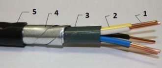
Electricity connection to a residential building is most often made using a self-supporting insulated SIP wire. It consists of several phase aluminum conductors covered with durable polyethylene insulation (cross-linked polyethylene) and a zero carrier. It can be with or without insulation. Often, for branches, a wire without a zero load-bearing core is used (SIP-4, SIP-5).
Compared to conventional cable, SIP has the following advantages:
- You can make the connection yourself. If the power line is de-energized, the connection process is completely safe. But if you don’t have the skills to work with electricity, it’s better to turn to electricians for help.
- Reliable power transmission in any climatic conditions. The wire can withstand high and low temperatures, gusts of wind and precipitation.
- Low price and durability.
SIP also has advantages over bare wires, which are also laid through the air:
- no porcelain insulators required;
- the distance between the cores decreases;
- there is no overlap of wires with each other under the influence of wind;
- Reactive losses are reduced due to the presence of insulation;
- Wire installation is simplified.
Piercing clamps for Vulture wires: operating principle
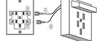
To describe how this device works, we give an example of its design.
Design of a piercing clamp for SIP
Designations:
- A – tightening bolt.
- B – sealed housing.
- C – eye for SIP.
- D – eyelet for the main conductor.
- E – cap, placed on the end of the SIP to ensure insulation.
- F – contact pad for the main core.
- G – gear-shaped contacts for SIP.
During the connection process, the bolt is tightened; under its pressure, the gear contact knives (G) cut through the SIP insulation and ensure reliable contact. At the same time, the contact pad (F) ensures adhesion to the main core. Please note that the design of the tightening mechanism is designed in such a way as to prevent bursting. That is, the bolt “breaks” when the threshold force is reached.
How to install correctly
As mentioned above, when this electrical installation is installed, there is no need to uninstall the cable itself. For example, you need to connect a branch to an existing line. How can such a connection of two wires be made (in fact, this will also be the fastening of the beginning of the outlet section)?
- The branch clamp is placed on the live line.
- The end of the wire for the branch section is inserted into the second groove.
- The bolt head is manually tightened until it stops.
- Then, using a spanner wrench, the bolt is tightened to such an extent that its head simply falls off. This indicates that the teeth of the device have reached the metal strands of the SIP wire.
The entire process is carried out only with dielectric gloves. Installation is quite simple, but it is not worth carrying out if you are not an electrician. There are certain restrictions and requirements regarding admission to this type of work. This is especially true for areas under voltage.
Instructions for connecting the line to the trunk using a SIP clamp
Before you start work, you need to stock up on tools, safety equipment, have reliable access to the line where you are going to connect, and prepare it and the line to be connected.
Branch clamps are needed that correspond to the parameters of the lines. Wrench (usually 13). Latex gloves. To prepare the main line for connection, you need to find connection points for each phase.
The main line wire is disassembled into phase wires
Since SIP wires are usually wound onto a supporting neutral wire, they should be disassembled into individual phases very carefully, without using metal tools, so as not to damage the insulation. It is enough to free up a little space so that you can insert the clamp with the hole for the main wire
To release the phase wire, you must use a dielectric wedge.
Attention! When releasing the phase wires of the main wire from the twist, you must remember that the main wires are under high electrical voltage, which is life-threatening. Damage to their insulation is unacceptable! Under no circumstances should you push the phase wires apart with a screwdriver, pliers, or anything sharp or metal.
It is necessary to use a dielectric wedge. For greater safety, carry out work with rubber gloves and rubber galoshes.
Attention! Before connecting the branch line to the main line, which is energized, you need to prepare the branch line in advance. She must be:
- mounted, the end of the branch line must be fixed near the connection point so that the free ends of the line wires are sufficient to bring them to the terminals;
- the other end is brought to the wiring point;
- equipped with a disconnecting device (switch);
- in this case, the disconnecting device must be in the “Off” position. There should be a warning sign on it: “DO NOT turn it on, people are working!”
- Let's understand the wires of both lines. If they are multi-colored, then we connect them according to the colors. The most important thing is that the zero phase (blue wire) of the main line is connected to the zero phase of the outgoing line. If there is a ground wire (green-yellow), then it should also be connected to the “ground” wire of the branch. The colors of the phases may differ slightly from each other; the sequence is not so important here, although technical accuracy requires that they correspond to each other, at least approximately.
- Installing a piercing clamp for wires on the main wire of one of the phases. Since the main wire is without a break, a clamp is installed on it through the slot holes. The pre-tensioning bolt must be sufficiently loosened and the clamp must be suitable for the wire gauge range.
- The wire from the phase of the outlet cable corresponding to a given phase of the main cable is inserted with its end into the second hole of the clamp. The clamp must be loosened so much that when passing the wire into the hole, its insulation is not damaged by the sharp teeth of the contact plate (and at the same time the teeth do not bend, since in this case there will be no good contact).
- The head of the bolt of the piercing clamp for SIP is carefully tightened. In this case, both wires and the clamp are held in the normal position so that there are no distortions. We work with gloves!, since after some tightening efforts the insulation will be broken and the phase will flow into the outlet line.
- We continue to tighten until the head of the bolt falls off - this will be the required force so that compression occurs, the SIP is punctured and reliable contact is established.
Installation of piercing clamps
The algorithm for organizing a tap using a piercing clamp is quite simple, but there are several nuances that need to be paid attention to:
- As a rule, devices of this type are designed in such a way that installation work can be carried out without turning off the power supply. That is, the tightening mechanism is isolated from the contact area. But, nevertheless, the electrician performing the connection must have the appropriate clearance group.
- To separate the core, special devices (separating wedges) should be used.
Separating wedges
Connecting SIP wires to each other
You cannot connect or extend SIP wires with piercing clamps. Even if it is a short section of up to 25m, for example the entrance to a house. That is why they are called branch clamps, and not connecting terminals.
To connect the wires, it is necessary to use connecting sleeves for crimping. You can read in great detail about all the nuances and errors of working with them in the article “How to connect SIP wires to each other.”
Moreover, it is not recommended to use such punctures to connect the main SIP to the anchor support, even if there is no tension there. Since the contact area in such a clamp is incommensurate with the cross-section of the main wire. And such a clamp, without consequences for itself and the connected wires, may not allow a full long-term load of 100 Amperes or more to pass through, not to mention the short circuit current.
Punctures with separate bolt tightening also have a shear head. It plays the role of a kind of “fuse”. Since the SIP wire is in a tense state and each core is subjected to longitudinal mechanical load, it is necessary to pierce the wire and plunge the teeth into the core itself just enough so as not to reduce the mechanical strength of the line by more than 20% .
There is no need to manually tighten the second nut after a breakdown if it seems to you that the contact is not good enough. This will only damage the supporting wire.
Some brands of clamps, for example Sicam, have a so-called Turbo option. It facilitates and simplifies the installation process.
The entire installation is divided into two stages:
- separate installation on the line. Take the untwisted clamp, insert it into the main wire and tighten the nuts with one hand so that the clamp is fixed.
- while the second end remains divorced. Calmly install the branch into it and complete the installation process.
SIP laying
SIP is a single-phase or three-phase wire, the phases of which are insulated with durable polyethylene, resistant to ultraviolet radiation, and the neutral wire is the load-bearing wire.
This is an aluminum strand braided around a steel core. The neutral carrier wire can be insulated or not; three insulated phases are wound on top of it. Such a wire works in the distribution of electricity from transformer substations within the building boundaries, which, in general, justifies the increased concern for safety. These wires are insulated very well and hermetically, since external wiring is subject to all natural influences.
When laying SIPs, they are pulled from support to support, the two wires are joined to each other using a sealed clamp, which is crimped. Thus, the contact of the spliced wire and the insulation of the SIP cable along the entire line from beginning to end remains sealed.
To connect a branch line to the main line, specially designed self-piercing branch clamps are used. The technology in this case does not require removing the insulation from the wire; the clamp connects two wires using a puncture method, and the clamp itself creates reliable insulation of the branch from the outside.
The technology is as follows:
- Install the clamp onto the main insulated wire through the hole provided for this purpose and securely fix it.
- Pass the external connecting wire through the second hole.
- Using a wrench (usually 13 or 17), tighten the clamp head. The dosage of force for the cable is that when twisting, after piercing the insulation of both wires inside the clamp and creating reliable contact, the head breaks off, and the contacts inside the clamp are securely fixed.
- After the head comes off, the connection is reliable, and the insulation is solid and sealed.
- The end of the branch conductor is sealed with a special cap.
Protective caps
With any branch, wire cuts appear, which must also be reliably sealed. To seal such terminations, protective caps are usually used.
The cap on the clamp can be built-in or removable. It is better to choose punctures with built-in ones. Since, being at a height, on a support it is not always convenient to take this cap out of a bag or pocket, and often it is completely lost.
Bare Wire Clamp
There are 2 main design types of such clamps - intended for insulated and “bare”, that is, cables without insulation. The latter are usually used in main power lines.
If it is necessary to make a branch from the main line, then there is no need for teeth to pierce the insulation. In this case, it is advisable to use a specialized clamp, in which a die without teeth is designed for the main side, while a standard design with teeth is used for the branch side. Of course, it is impossible to install such a system without de-energizing the line.
Connecting two wires on one puncture
Another important point when using piercings is that it is prohibited to connect more than one branch on one sealed piercing clamp, unless this is provided for by its design.
It would seem that you have two outgoing cables with a cross-section of 6mm2. If you twist them together or even insert them inside the clamp without twisting, then nothing prevents you from tightening the contact in this way. This technique is often used when connecting several lamps through one piercing clamp.
However, just the same contact over the entire area of the outgoing core will no longer be sufficient. Moreover, in this case the insulating rubber gasket will not be able to compress the wire from all sides. And accordingly, we are no longer talking about any tightness. Moisture will easily penetrate inside the puncture, flowing down the surface of the insulation of the two wires.
Errors when connecting branch lines to the main line
- When installing the clamps, do not press the head completely. There may be a bad connection.
- Second time use branch clamps. Even if it looks like a working new one, during the first installation the cutting teeth may have been damaged (bent, broken), and contact in this case may not be possible.
- Connect wires that do not branch off from the main line, but are equivalent to each other.
- Try to use a clamp to connect not one, but two lines. Since the cutting contacts are centered along one core, they must accurately cut through the central part and enter the conductor. Otherwise they will miss or bend.
Reusable piercing clip
Another commonly used piercing clamp is a clamp with a separate bolt tightening function. Due to this, this clamp is considered reusable, but only from the point of view of connecting branches.
If you often have to connect and disconnect the input to the house or temporary objects from self-supporting insulated wires (welding stations, portable electrical installations), then this device is the only way to do this painlessly for the line itself.
Since in this case nothing happens to the puncture on the SIP, only the bolt that tightens the outgoing cable is unscrewed, which also does not have any teeth.
In this case, the insulation from the branch core must be removed by 1-2 cm. Another advantage of these clamps is their versatility. Through them you can connect not only the entrance to the house and street lighting, but also the grounding drains of the neutral conductor.
Here are their main manufacturers, technical data and characteristics:
Sicam TT1D-4D
KVT ZPK
Advantages of branch compressors
In work, the use of such technology provides a number of undeniable advantages, in particular:
- Ability to work under voltage. Using the clamp, you can make a tap from the main SIP without de-energizing the line.
- The ability to connect wires made of different metals (copper and aluminum), provided that they are single-core.
- Tightening control - using a breaker head (in particular, in the P95 branch clamp it is aluminum) or using a dynamometer. In the first case, breaking the head means achieving the required pressure.
- Convenient removal method using a second screw.
- The case is hermetically sealed for the corresponding models. Leak tests are carried out in water using high voltage current.
- Compensation for temperature expansions.
- Speed of installation work.
- There is a wide range of wire gauges that can be connected this way.
Manufacturers
The most commonly used piercing clamps are those manufactured by Ensto and Niled. The first manufacturer is known for producing fittings for all types of SIP cables. The company's product range includes both lightweight models, which are made of plastic, and the most durable devices, the material for the production of which is various alloys.
- A special feature of Ensto clamps is the pyramidal design of the piercing teeth, which increases the contact area and reduces the impact on the wire, preventing it from being damaged.
- Most Popular Clamps Niled differentiates itself by tailoring its products to suit the local market. For example, special devices for cables with small cross-sections have been developed for Russia.
So, piercing clamps are used to ensure a stable connection between main power lines and their branches. Due to their design features, they practically do not damage the wire and meet all safety requirements; you just need to follow the technology for installing connecting devices.