The electricity supplied to our apartments has its own standards. For example, for a 220 volt power supply network, the deviation should not exceed 10% of the nominal value. Such a difference in voltage does not always have a beneficial effect on the functioning of sensitive electrical devices for household use and lighting devices. Organizations that supply electricity use transformers for the power lines that carry electric current to homes.
When operating under load, the line produces a lower voltage limit. With a further increase in load, the standard limit decreases, since the power of the substation is exhausted. The 380 V network also functions. This explains the operating mode of the installations under normal conditions. In reality, the supply of electricity to homes in winter can be much worse.
This situation can be corrected by using devices that stabilize the basic parameters of the electric current. Stabilizers are used in different places. The cost of such a device is small, and its installation and connection is quite simple, and allows you to do all the work yourself.
Determining the type of protection
Currently, there are stationary devices that stabilize voltage, which are installed throughout the entire house, as well as portable models that can serve only a few electrical devices. In addition, stationary stabilizers are three-phase or single-phase. It depends on the conditions of use. Connections to 1-phase and 3-phase networks have their differences.
In an apartment or your own house, it is better to connect a 1-phase stabilizer near the switchboard. This makes it possible to protect the entire network from the effects of overloads. Therefore, let's look at the installation instructions for a 1-phase device.
Lighting
- Lighting control panel
- Installation of chandeliers and lamps
- Installation of lighting systems
- Installation of fluorescent lamps
- Installation of ceiling lights
- Loft lighting
- Installation of Armstrong lamps
- Installation of Grilyato lamps
- Light control from the remote control
- Installation of spotlights and spots
- Installation of track lights
- Apartment lighting
- Installation of lamp posts
- Street lighting
- Warehouse lighting
- Parking lot and parking lot lighting
- Road lighting
- Street lighting in SNT
- Outdoor LED lighting
- Lighting of entrances of apartment buildings
- Disposal of lamps and fixtures
- Electrics and lighting underwater
- Lighting 36 volts
- Lighting for basements and attics
- Facade lighting
- Outdoor gazebo lighting
- Architectural lighting
- Lighting decoration with garlands
- Connecting LED strip
- Autonomous and emergency lighting
- Lighting control
- Lighting Maintenance
- Lighting system repair
- Lighting control from multiple locations
- Touch light switches
- Installation of pass-through switches
- Installation of a pulse relay
- Connecting electric motors
- Connecting a magnetic starter
- Connecting a time relay
- Temperature relay connection
Choosing an installation location
When installing it yourself, all responsibility falls on you, since if installed incorrectly, the device may fail, a fire may occur, etc.
To connect a voltage stabilizer in an apartment with your own hands, you need to consider some tips:
- The room must be dry and ventilated, since the main cause of the malfunction is the presence of moisture in the device body.
- When installing in a niche, check how safe the finishing materials are for flammability.
- It is necessary to provide a gap between the walls and the stabilizer. It is necessary to retreat 10 cm.
- For wall mounting, check that the mount can support the weight of the wall stabilizer.
Circuit solutions for stabilizing the 220V power grid
When considering possible circuit solutions for voltage stabilization, taking into account relatively high power (at least 1-2 kW), one should keep in mind the variety of technologies.
There are several circuit solutions that determine the technological capabilities of devices:
- ferroresonant;
- servo-driven;
- electronic;
- inverter
Which option to choose depends on your preferences, available materials for assembly and skills in working with electrical equipment.
Option #1 - ferroresonant circuit
For self-production, the simplest circuit option seems to be the first item on the list - a ferroresonant circuit. It works using the magnetic resonance effect.
Block diagram of a simple stabilizer made on the basis of chokes: 1 – first throttle element; 2 – second throttle element; 3 – capacitor; 4 – input voltage side; 5 – output voltage side
The design of a sufficiently powerful ferroresonant stabilizer can be assembled using only three elements:
- Throttle 1.
- Throttle 2.
- Capacitor.
However, the simplicity in this option is accompanied by a lot of inconveniences. The design of a powerful stabilizer, assembled using a ferroresonant circuit, turns out to be massive, bulky, and heavy.
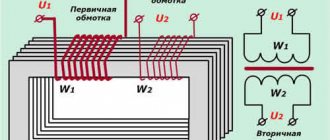
Option #2 - autotransformer or servo drive
In fact, we are talking about a circuit that uses the principle of an autotransformer. Voltage transformation is automatically carried out by controlling a rheostat, the slider of which moves the servo drive.
In turn, the servo drive is controlled by a signal received, for example, from a voltage level sensor.
A schematic diagram of a servo-drive device, the assembly of which will allow you to create a powerful voltage stabilizer for your home or country house. However, this option is considered technologically outdated
A relay-type device operates in approximately the same way, with the only difference being that the transformation ratio changes, if necessary, by connecting or disconnecting the corresponding windings using a relay.
Circuits of this kind look technically more complex, but at the same time they do not provide sufficient linearity of voltage changes.
It is permissible to assemble a relay or servo-drive device manually. However, it is wiser to choose the electronic option. The costs of effort and money are almost the same.
Option #3 - electronic circuit
Assembling a powerful stabilizer using an electronic control circuit with an extensive range of radio components on sale becomes quite possible. As a rule, such circuits are assembled on electronic components - triacs (thyristors, transistors).
A number of voltage stabilizer circuits have also been developed, where power field-effect transistors are used as switches.
Block diagram of the electronic stabilization module: 1 – input terminals of the device; 2 – triac control unit for transformer windings; 3 – microprocessor unit; 4 – output terminals for load connection
It is quite difficult to manufacture a powerful device completely electronically controlled by a non-specialist. You cannot do without experience and knowledge in the field of electrical engineering.
Therefore, it is advisable to consider this option for independent production if there is a strong desire to build a stabilizer, plus the accumulated experience of an electronics engineer. Further in the article we will look at the design of an electronic design suitable for making it yourself.
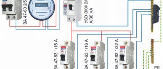
Network connection
Independent connection to the stabilizer network is not very difficult. On the back of the device there is a block with terminals for five connectors. Most often, the wires alternate like this: phase and zero, grounding, load phase and zero.
To connect, you just need to make the right choice of cable cross-section. Next, self-installation is carried out. Connection diagram for a 220 volt stabilizer:
Necessary materials
To connect, you will need the stabilizer itself. It must be selected in advance, taking into account which device will be connected to it. The following materials are also needed:
- Three-core cable VVG. Its cross-section must coincide with the cross-section of the input cable on the switch or input circuit breaker.
- Three-position switch to activate the stabilizer. It has 3 states - the first consumer is on, the second consumer is on and off. Instead, you can use a regular modular switch, but in this case, when disconnecting from the stabilizer, the entire room will be de-energized each time.
- PUGV wires of different colors.
The stabilizer must be mounted before the energy meter. Any other connection is prohibited. This is due to the fact that the stabilizer has its own idle speed and consumes electricity. It must be taken into account when paying bills.
It is also recommended to install an RCD or differential circuit breaker in the circuit before connecting the stabilizer.
Types of stabilizers
When you decide to install a stabilizer, you need to select and purchase a stabilizer model. In order not to get confused with choosing the optimal device option, you need to know that all devices perform a similar function, but have differences in the principle of operation. To obtain high-quality energy for your home, 2 types of devices are suitable:
A servo drive device that has a comparison circuit that serves to control a small motor. It rotates in different directions and moves a slider that removes the current. As a result, the output produces a stable voltage value of 220 volts. The advantage of such a device is smooth regulation. This makes it possible to obtain voltage without drops.
The relay version of the stabilization device has its own differences in its operating principle. The device housing contains a transformer with terminals. The input voltage is multiplied by a factor and applied to each output. Electronic elements control the action of the relay unit, which switches the transformer outputs if necessary. Due to this, a voltage of 220 volts is obtained at the output of the stabilizer. A negative factor of such devices is the appearance of small voltage surges when stages are switched.
The third type of stabilizer is an electronic device. It is an expensive device, although its operating principle is not much different from a relay device. Instead of a relay, it has an electronic switch that switches the terminals of the transformer using thyristors.
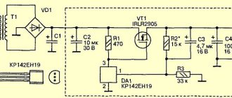
Homemade apparatus
A high-quality stabilizer for several kW and an output current of more than 10 amperes can be assembled based on an old transformer installed in a welding machine. However, such a “blank” is not easy to find. Moreover, the current technology is suitable for subsequent use for its intended purpose. For reproduction at home without professional skills, the circuit presented below on electronic components is suitable. It will provide:
- prompt correction of output parameters with a switching speed of no more than 8-12 milliseconds;
- operating input voltage range 125-265 V;
- power of connected consumers up to 5.5 kW.
Electrical and wiring diagram, printed circuit board
Advantages of a homemade device
In addition to good technical parameters, the following advantages should be noted:
- reasonable costs;
- the ability to independently perform repair operations.
Flaws
The consumer parameters of the product largely depend on the assembly. In this case, it is assumed that there are no well-developed skills and professional installation (measuring) equipment. On the other hand, careful execution of individual work operations will help control quality more thoroughly than the actions of third-party contractors.
Differences from factory models
Modern production is characterized by a high level of automation. This reduces the harmful influence of the “human factor” and reduces costs. With the use of professional technologies it is easier to ensure a perfect appearance. However, when creating a homemade product, you can use unique technical and aesthetic solutions.
Accessories
Main components (functional components):
- transformer power supply with diode temperature compensation and comparator;
- rectifier with divider;
- transistor load connection delay circuit;
- controller on digital chips;
- LED indication of operating modes and emergency situations;
- keys from optitron pairs.
Features of home production
Standard transformers TPK-2-2x12V are suitable. If necessary, you can create analogs with your own hands, using PEVs with a conductor diameter of 0.064 mm (8669 turns) and 0.185 mm (522 turns) in the primary and secondary windings, respectively.
Stabilizer stages
All stabilizer options have several stages of operation. The quality of the output voltage depends on their number. To understand the operation of the stages, consider an example. When a voltage of 220 volts of normal value is applied, the device runs it according to the circuit without changes. When the voltage drops to the limit values, the electronic key or relay connects the 1st stage, and a stable voltage of 220 volts appears at the output.
The subsequent voltage drop forces the stabilizer to switch to other stages, which will allow it to provide the necessary 220 volts. When there are no longer enough steps, the stabilizer will not be able to increase the voltage. The greater the number of stages, the wider its voltage adjustment interval.
Tips for connecting a voltage stabilizer:
- Before installation, always turn off the mains power at the electrical panel.
- Connect auxiliary protection of the device in the form of a circuit breaker and residual current device. This extends its service life. It is advisable to install the automation behind the meter, but in front of the protection.
- The electrical network for domestic use must have a grounding loop. Installation of the stabilizer without grounding is prohibited according to electrical safety rules.
- Installation of a stabilizing device in the house before the meter is prohibited. The best option for installing the stabilizer would be to use it according to the above scheme.
- It is forbidden to connect the stabilizer immediately after bringing it into the apartment from the cold. Condensation accumulates inside the case, which can severely damage the device when turned on and shorten its service life. Its installation on the street is also prohibited.
- A low power stabilizer of up to 5 kilowatts is connected directly to the outlet. This method is acceptable for garage conditions, country houses. Sometimes a portable stabilizer is installed separately for digital equipment, for example, on a computer, TV, etc.
For a three-phase 380 volt network, the stabilizer is connected to one device per phase, connecting them with a star circuit. This method achieves savings on the purchase of devices, as well as on its maintenance and repair, since a 3-phase device is much more expensive.
- After installation, you need to check the correctness of the connections and installation. To do this, connect automatic input devices in the switchboard. Crackling, buzzing, and sparking are not allowed. If there are no such signs, then the voltage stabilizer is connected correctly.
- It is not allowed to connect the stabilizer to a load exceeding the power of the device. Its power reserve must be at least 30%.
- The correct installation diagram is most often depicted on the device body. First you need to focus on this diagram. If there is no such scheme, then these recommendations are the best option. Popular models of stabilizers are connected in this way.
Every year it is necessary to check the reliability of the wiring connections in the terminal blocks and, if necessary, tighten them.
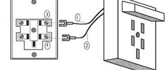
Connecting wires
Phase - white wire, zero - blue, ground - yellow-green
To connect, you need to remove the protective cover on the stabilizer. The input and output cables are threaded through the hole and clamped using terminals. The phase of the input cable must be connected to the input of the Lin stabilizer. Zero – to terminal N. Ground to the corresponding terminal. If there is no ground, the core is screwed under the screw of the device body.
After applying voltage from the distribution box, you need to supply stabilized power back to the panel. To do this, you need to connect via the output cable from the stabilizer. Phase - to the Lout output, zero - to N, ground - to the same place where the grounding conductor from the input cable is connected.
The last step is a visual inspection of the correct connection and testing of the system.
Features of connecting the stabilizer to a three-phase network
Three-phase stabilizers for each block have their own terminal blocks. When they are connected to the network, there must be a uniform distribution of single-phase consumers. This can be achieved by connecting to different blocks on the stabilizer.
Typically, such circuits can be connected in manufacturing and industrial enterprises. This is due to the high cost of the device itself.
Scheme No. 1
Scheme No. 2
In domestic conditions, three-phase power consumers are connected through a single-phase device.
Connection diagrams
Open the terminal block cover of the stabilizer:
We connect the stabilizer according to the diagram.
The stabilizer is located behind the wall, so there is a hole through which four wires pass: phase for the stabilizer, zero for it, zero for the apartment, phase also to the apartment.
Once again, check that the connections are correct and turn on the power.
The display shows the output voltage and current.
How to properly connect an electric generator?
How to properly connect an electric generator as a backup source in a house or on site?
If you look at the Internet, you can find hundreds of recommendations and diagrams for connecting a generator, which is what most buyers use. But most attempts, unfortunately, turn out to be unsuccessful and lead to a call to the service center, we see this all the time. That is why we decided to give basic recommendations for connecting an electric generator. This article is not a guide to action and is for informational purposes only. Perhaps reading it will stop you from making rash actions without relevant experience and will protect you from wasting money on equipment repairs.
The easiest way to connect a generator is through an extension cord into any outlet in the room. It works as follows: if there is no electricity, you need to start the electric generator, let it warm up and connect it through an extension cord to any outlet in the room. Agree, it’s quite a simple procedure at first glance. But you need to remember that the generator must be completely disconnected from the central power supply network, otherwise it will end in failure and will cost a considerable amount of money for repairs. With this scheme, the input circuit breaker is turned off or the plugs are unscrewed and it is necessary to turn off not only the phase, but also the zero! It is also very important not to overload this line. It turns out that everything is not as simple as it seemed. After all, the human factor is present everywhere and at one moment you can perform operations in the wrong order or forget something. The method is quite risky despite its simplicity.
The next way to connect an electric generator is through a three-way switch or changeover switch. This is a safer connection method that eliminates the simultaneous use of the mains and generator. This circuit has three operating positions: the mains is connected, the generator is connected, or everything is turned off. When connecting a changeover switch, the electrical network is connected to its upper contacts, the generator to the lower ones, and the energy consumers of the room to the middle ones. A three-way switch is connected according to the same principle. In the absence of electricity, this scheme operates as follows: start the generator and give it time to warm up, switch the switch to the lower position. When electricity appears, return the switch to its place and turn off the generator. This method is much simpler and safer than the first, but we want to draw your attention to one more method.
Connecting the generator via AVR . This is a complete automatic generator control system. ATS is an automatic reserve entry panel that partially or completely eliminates operator participation. This automation constantly monitors the voltage of the central power supply network and, in case of its absence, will start and warm up the generator, after which it will switch the load to the backup power source. When the voltage in the network is restored, the ATS will perform all operations exactly the opposite. First there will be a switchover to the main network, and after a while the generator will be turned off. This is the easiest and safest way to connect a generator, but with one caveat: to fully automate the process, a generator with autostart is required. In the figure you will find a clear example of connecting an ATS, but it is quite difficult to carry out installation on your own without skills and it is better to use the services of a specialist in this field.
On the pages of our store you will find another option for creating a fully automatic power supply system without purchasing an ATS. These are generators with automatic start and transfer function, Huter DY6500LXA and Huter DY8000LXA. These generator models already have a built-in automatic start system, which will start the unit in the absence of voltage in the network and will also automatically turn it off when electricity appears. To start these models with an electric starter, a battery is required.
If you have questions, we will be happy to answer them. Use the feedback form on the website or visit our specialized store in Yekaterinburg at st. Novostroya 1A, office 105.
We guarantee the quality and authenticity of our products! We are official representatives of the manufacturer!
We deliver very quickly! As a rule - on the day of order! We have our own courier service!
Upon receipt, the product can be unpacked, checked, launched and turned on!
We give gifts and discounts to birthday people, pensioners, veterans and beloved customers!
We are pleased to present you the entire range of products from the RESANTA, HUTER, WIKHR brands - these are voltage stabilizers, thermal equipment, welding equipment, as well as measuring instruments and electrical products, which are very well known for their quality among professionals and amateurs. HUTER petrol and garden equipment are undeniably ideal in price and quality petrol generators, trimmers, brush cutters, lawn mowers and motor pumps, the range of which will not leave even the most sophisticated consumer indifferent.
Why do you need a 220 V voltage stabilizer for the home and its functions in the household network
In Soviet times, everyone was told that soon the standard of living of cities and villages would be equal, but now we can only see the opposite. Power surges in villages are common. After all, small substations that require repairs are completely incapable of servicing houses. And progress adds more work for them - the amount of household appliances designed to make life easier ends up overloading the transformer. As a result, when equipment with high power consumption is switched off in several places, a voltage surge occurs due to the fact that the old transformer does not have time to react. The result is burnt-out household appliances for those connected to the same phase.
The main task of the stabilizer is to prevent increased voltage from damaging household appliances, regardless of their purpose. Let's try to understand how it works.
This itself is a complex device with many electronics
Rules for safe operation
- Prevent access to the product from children and unauthorized persons, as well as people unfamiliar with the operating and safety rules.
- Do not repair a faulty voltage stabilizer yourself.
- Avoid the appearance of flame sources and smoldering combustion near the stabilizer. Do not smoke near the product!
- Do not store explosive, flammable or combustible materials near the product.
- Do not place or operate the stabilizer in an explosive environment.
- Ensure prompt availability of primary fire extinguishing equipment near the installation site.