Electrical engineering cannot exist without the special circuits and projects accompanying it. Therefore, it is very important for a specialist to be able to read them correctly and use them exactly as intended. In many cases, all elements, including the RCD designation on a single-line diagram, are made rather conditionally, so that one can imagine a complete picture of the entire graphic project. As a rule, the conventional image of an RCD resembles a regular switch, with poles, wires, etc., depicted symbolically. An experienced electrician is well versed in such diagrams, reads them confidently and does not make mistakes during work.
Designation of electrical elements on diagrams
To understand what exactly is shown on a diagram or drawing, you need to know the decoding of the icons that are on it. This recognition is also called blueprint reading. And to make this task easier, almost all elements have their own symbols. Almost, because the standards have not been updated for a long time and some elements are drawn by everyone as best they can. But, for the most part, symbols in electrical diagrams are in regulatory documents.
Symbols in electrical circuits: lamps, transformers, measuring instruments, basic components
RCD designation on a single-line diagram
The main groups of RCD designations (graphic and alphabetic) are used very often by electricians. The work of drawing up work diagrams, schedules and plans requires very great care and accuracy, since a single inaccurate indication or mark can lead to a serious error in further work and cause the failure of expensive equipment.
In addition, incorrect data can mislead third-party specialists hired for electrical installations and cause difficulties when installing electrical communications.
Currently, any ouzo designation on a diagram can be represented in two ways: graphic and alphabetic.
Which regulatory documents should be referred to?
Of the main documents for electrical diagrams that refer to the graphic and letter designation of switching devices, the following can be distinguished:
- — GOST 2.755-87 ESKD “Conventional graphic designations in electrical circuits of devices, switching and contact connections”;
- — GOST 2.710-81 ESKD “Alphanumeric designations in electrical circuits.”
RCD designation on the diagram according to GOST
All residual current devices are marked on the diagrams using graphic and alphabetic images. This symbolism is determined by regulatory documents: GOST 2.755-87 ESKD “Conventional graphic symbols in electrical circuits. Switching and contact connection devices." Marking is determined in accordance with GOST 2.710-81 ESKD “Alphanumeric designations in electrical circuits.”
However, in general, these documents do not provide complete information about what exactly the RCD designation should be on a single-line type diagram. That is, no special requirements are put forward in this case. Therefore, many electricians mark some components and devices with their own developed meanings and labels, slightly different from the usual standard designations.
Sometimes the symbols printed on the body of the protective device are used as a basis. That's why. Based on the purpose of the RCD, this device is divided into two components on the electrical circuits - a switch and a sensor that responds to differential current and actuates the contact disconnection mechanism.
The current state standards (GOST) do not regulate the graphic and letter designation of RCDs (residual current devices); there are no additional graphic symbols that would allow a more precise description of the main functions and properties of standard equipment.
RCD is one of the main elements of single-line electrical circuits, therefore manufacturers of modular equipment and designers have adopted the following symbol for it:
Such a schematic display of residual current devices most accurately shows its operating principle and distinguishes it from other modular equipment, if you know what an RCD is and how it works.
At the same time, since state standards do not regulate the type of RCD, it is necessary to show on diagrams and plans a block with conventional graphic symbols (CGI), in which a transcript and explanations for the graphic elements must be given, even if it is decided to use a different type from the one presented. The ability to develop symbols yourself, if they are not in the standards, is indicated in GOST 2.702-2011.
The letter marking of the RCD is QF , if you use the rules for their formation according to GOST 2.710-81 ESKD (READ PDF) “Alphanumeric designations in electrical circuits.” This is completely identical to the designation of a circuit breaker and some other modular devices, making single line diagrams less readable and understandable.
Many people enter their own letter designations: Q, QFD, QDF, etc. which, if we rely on current standards, are incorrect, do not reveal the functions of the RCD, but help to distinguish them from other elements of protective automation on single-line diagrams.
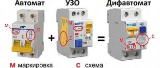
This can be important, especially if the circuit simultaneously contains RCDs and automatic circuit breakers. Their graphic symbols are similar and it is not always easy to distinguish them from each other. Considering that electrical installation designers often simplify the graphic symbols used as much as possible, omitting important details.
Let's consider the conventional designation of a differential automatic machine on a single-line diagram and compare it with an RCD.
Electrical engineering cannot exist without the special circuits and projects accompanying it. Therefore, it is very important for a specialist to be able to read them correctly and use them exactly as intended. In many cases, all elements, including the RCD designation on a single-line diagram, are made rather conditionally, so that you can clearly imagine the complete picture of the entire graphic project. As a rule, the conventional image of an RCD resembles a regular switch, with poles, wires and other parts depicted symbolically. An experienced electrician is well versed in such diagrams, reads them confidently and does not make mistakes during work.
List of the most important characteristics of automatic machines
Differential automatic machines (difavtomats) are designed on the principle of combining two protective functions in one device and have the capabilities of an automatic circuit breaker (AB) and an RCD.
As automatic devices, they protect power lines from overloads and short circuits (short circuits), and as RCDs, they protect a person from electric shock.
Important
The second protective function of these devices is explained by their ability to respond to the slightest leakage of electricity to the ground caused by a violation of the insulation of conductive parts or the touch of a living creature to them.
The built-in RCD circuit of a differential circuit breaker operates on the principle of comparing current components flowing in the forward and reverse branches of the controlled circuit. If the balance of these quantities is disturbed (the appearance of a current differential), the difference signal is sent to the executive relay, which instantly disconnects the dangerous section from the power line. What are the characteristics of difavtomats?
Operating current and speed
The design features of difavtomats are the reason that they have combined characteristics used in describing the operation of both AV and RCD. The main operating characteristic of these electrical products is the rated operating current, at which the device can remain turned on for a long time.
RCD connection diagram, RCD designation on the diagram, connection diagram for single-phase and three-phase RCD.
Installing an RCD significantly increases the level of safety when working on electrical installations. If the RCD has high sensitivity (30 mA), then it provides protection against direct contact (touch).
However, installing an RCD does not mean taking the usual precautions when working on electrical installations.
The test button must be pressed regularly, at least once every 6 months. If the test does not work, then you need to think about replacing the RCD, since the level of electrical safety has decreased.
Install the RCD on the panel or housing. Connect the equipment exactly according to the diagram. Turn on all loads connected to the protected network.
The RCD is triggered.
If the RCD trips, find out which device is causing the trip by sequentially disconnecting the load (we turn off the electrical equipment one by one and see the result). If such a device is detected, it must be disconnected from the network and checked. If the electrical line is very long, the normal leakage currents can be quite high. In this case, there is a possibility of false positives. To avoid this, it is necessary to divide the system into at least two circuits, each of which will be protected by its own RCD. You can calculate the length of the electrical line.
If it is impossible to determine in a documentary way the sum of leakage currents of wiring and loads, you can use an approximate calculation (in accordance with SP 31-110-2003), taking the load leakage current equal to 0.4 mA per 1 A of power consumed by the load and the leakage current of the electrical network equal to 10 μA per meter length of the phase wire of the electrical wiring.
Differential automatic: electromechanical, electronic, technical characteristics
What is a circuit breaker? A device that protects electrical wiring and electrical appliances from short circuits and overloads. What is an RCD? This is another device that responds to leakage current that occurs when insulation deteriorates or a person touches live parts.
These devices operate on different principles, but are united by one task: to protect electrical equipment and consumers from problems that arise during accidents in the electrical network. They are installed in distribution or group panels; cable lines leading to sockets are connected to them.
Cable lines are always protected from short circuits and overloads. But if it is necessary to provide protection against leakage, it is necessary to install an RCD as an additional protective device.
Connecting RCD and circuit breaker
The PUE obliges the installation of an RCD in the following cases:
- when consumers (sockets) are outdoors (on the street);
- to protect sockets and consumers in high-risk areas (bathrooms, showers);
- in cases where circuit breakers cannot effectively protect due to low short-circuit currents.
The last point requires some clarification. The further the consumer is from the power source (transformer at the substation), the greater the length of the electrical wiring between them.
Conductors have electrical resistance, so it increases between the source and the receiver.
During a short circuit, the current passing through the electrical wiring is limited by the small internal resistance of the source (the resistance of the secondary winding of the transformer) and the equivalent resistance of the conductors between the short circuit point and the source.
Therefore, the magnitude of the short circuit current decreases with increasing distance from the substation. At remote points, it is possible that the machine will not sense this current.
Of course, with a time delay its thermal protection will work. But if there is a short circuit to the housing connected to the PE bus of the shield, for this time it will be under a life-threatening potential.
This cannot be allowed; this is why the PUE prescribes the protection of such RCD consumers.
The PUE prohibits the installation of an RCD without installing a circuit breaker in series with it . Therefore, when using differential protection, the cable line is protected by two devices. Additional wires appear in the shield, its complexity increases slightly. In addition, the RCD also takes up additional space on the DIN rail. What if it’s already missing?
Differential automatic
To simplify the design of distribution panels and compact placement of elements inside them, differential circuit breakers are used. Their housing contains protection devices against short circuits, overloads, and leakage currents. In essence, this is a circuit breaker and an RCD in one housing.
Technical characteristics of differential automatic machines
A differential automatic machine has technical characteristics characteristic of both automatic machines and RCDs.
Rated current . It means the maximum possible current that the contact system of the device can pass without damaging it. The same value is used to calculate other characteristics of the device.
Cut-off response characteristics . The most common:
| Type C | 5-10 rated currents |
| Type D | 2-5 rated currents |
It is marked by applying the corresponding letter before the number indicating the rated current.
Marking of rated current and characteristics of the difavtomat
Example:
C40 – the rated current of the difavtomat is 40 A, the cutoff operates within the range (5-10)∙40 = 200-400 A.
The current value for a particular device lies in this range. It can only be known by measuring it using devices capable of producing and measuring such currents.
Residual current marking
Differential operating current . Takes values:
| Scale of differential currents of difavtomats, mA | ||||
| to protect outgoing lines | for introductory and group dial machines | |||
| 10 | 30 | 100 | 300 | 500 |
This figure is the upper ceiling of the leakage current value at which the difautomatic device will operate. The real current is measured by special devices that simulate the occurrence of difcurrent and measure its values at the moment of operation.
Type of residual current device . Marked with a letter index or a picture.
Marking of types of automatic devices and RCDs
It means to which shape of the current waveform the circuit breaker reacts.
| Marking | Current waveform | Application |
| AC | Sine wave only | Heating devices. |
| A | Sine and pulsating constant | Electronic household appliances, washing machines |
| IN | Sine wave, pulsating, constant smoothed | Industrial semiconductor devices |
Just like RCDs, differential circuit breakers are also selective. They differ from conventional ones only in the presence of a time delay for shutdown and increased electrodynamic stability.
Selective automatic devices are used as introductory protective devices. They need a time delay to allow the devices connected after the input to turn off the differential current.
If this does not happen, the selective machine is triggered. Electrodynamic stability is the maximum short circuit current that a device can withstand without damage.
For selective automatic circuit breakers, it is increased so that they can easily withstand long-term emergency modes with high currents.
Selective automatic devices are marked with letters, depending on the response delay.
| Letter designation | Response delay, ms |
| Type S | 200 – 300 |
| Type G | 60 – 80 |
Electromechanical or electronic – which is better?
By analogy with RCDs, difavtomats are manufactured either with an electromechanical residual current device or with an electronic one.
Basic designations
We will consider in more detail the order of labeling of a difavtomat (location of its characteristics) using the example of a domestic product of the “AVDT32” brand, used in protection circuits for industrial and household electrical networks.
For the convenience of systematizing the information presented, a graphic designation will be understood as a certain marking position.
The first position indicates the name and series of the automatic machine. From this designation it follows that it is a differential type AV with built-in protection against dangerous leakage currents. The difavtomat is intended for use in single-phase alternating current electrical networks with a rated voltage of 230 Volts (50 Hertz).
In the place corresponding to position No. 3 (above), such a characteristic as the value of the rated differential short-circuit current is indicated.
Sometimes in this place you can see the value of the maximum switching capacity of the device, indicating the value of the maximum current at which the automatic circuit breaker can be turned off many times.
At the same position, but below, there is a graphic designation of the type of built-in circuit breaker (in this case it is type “A”, designed to work with leakages of pulsating direct and sinusoidal alternating currents).
In place of the 4th position you can see a modular diagram of the difavtomat, which indicates the elements included in its composition that are involved in the implementation of protective functions. For RCBO32 in this diagram the following modules and assemblies are indicated by symbols:
- electromagnetic and thermal releases that provide protection of lines from short-circuit currents and overloads, respectively;
- a special “Test” button, necessary for manually checking the serviceability of the machine;
- amplification electronic module;
- executive unit (relay line switching).
At position number seven, the speed-related characteristic of the emergency operation of the electromagnetic release is indicated in the first place (for our example, this is “C”).
Immediately followed by the rated current indicator, indicating the value of this parameter in operating mode (over a long time).
The minimum shutdown (trigger) current of an electromagnetic type release for a difavtomat with characteristic “C” is usually taken equal to approximately five rated currents. With this current characteristic value, the thermal release operates in approximately 1.5 seconds.
In the eighth position there is usually a “delta” icon with an indicator of the rated leakage current, which turns off the differential device in case of danger. These are all the basic electrical characteristics.
Explanation of markings
The marking is applied to the body of the RCD, which makes choosing the right model more convenient and easier. First of all, the manufacturer is indicated, but there is also other important information:
- “UZO” or “VD” means that this is a residual current device;
- 16A – maximum current for which the product contacts and other internal elements are designed;
- In 30mA – leakage current at which the RCD will trip;
- 230V and 50Hz – voltage and frequency at which the unit operates;
- S - selective RCD;
- sign "
" - this means that the device is triggered by AC leaks.
In addition, there are inscriptions near each contact for the correct connection of the RCD:
- N (top) – the incoming neutral conductor is connected to this contact;
- 1 (top) – the incoming phase conductor is connected here;
- 2 (bottom) – the phase conductor going to the load is connected to this place;
- N (bottom) or absence of a letter - the neutral conductor going to the load is connected.
To choose an RCD that is ideal for your electrical network, you need to understand the markings in detail, even though this task is very painstaking and tedious.
What do the inscriptions on the switch mean?
Symbols, numbers, letters, diagrams are applied to technical plastic with special indelible paint. Even with older models they remain readable. It is assumed that the user or electrician, barely glancing at the machine, should quickly determine its current characteristics and voltage.
Manufacturer and model of the machine
The top line of the marking block is occupied by the brand name. A certain color is selected for printing, often bright, and sometimes even by the shade you can determine which manufacturer’s products are in front of you.
Experienced electricians suggest not to skimp when buying machines and to purchase devices only from proven European brands: Schrack Technik , Schneider Electric , ABB , Schaltbau , Moeller , HAGER , Legrand . There are several Russian brands that you can also safely trust: Elektrotechnik , TDM ELECTRIC , EKF .
The line below indicates the device model. All other inscriptions, except for the manufacturer's name, are usually printed in gray, so the series can be easily confused with technical specifications.
In order not to be mistaken, we look exactly at the second line. The line or model designation may look like this: BA63 , SH200 , Acti9 .
You can try to decipher the series, but the technical characteristics are not always hidden behind the letters and numbers; more often it is just the name of a specific model.
The line designation can be printed either on a general gray background or on a colored line, which is located directly under the brand.
Determination of time-current characteristic
The next line is a combination of a Latin letter and a number. The first letter indicates the time-current characteristic. It refers to how quickly a switch operates when a certain amount of current flows through it. There are five different types in total: “B”, “C”, “D”, “K”, “Z”, but in everyday life machines B, C, D are used.
Information signs
The fifth position shows the temperature characteristics of the protective device (from - 25 to + 40 degrees), and the sixth position contains two signs.
One of them informs the user about the certificate of conformity, that is, it indicates the current domestic GOST for the difavtomat (GOST R129 - for this case).
Directly below it is a characteristic encoded in the form of letters and numbers. This is the designation of the organization that issued the certificate.
This sign informs the consumer about the legal origin of the product and its quality and, if necessary, ensures the legal protection of the device.
To the right of it are the certification and GOST data for this model regarding its fire safety.
And finally, in the place corresponding to the second position, the logo of the manufacturer’s trademark (in this case, “IEC”) is applied.
Uzo designation on the diagram
To protect against current leakage, residual current switches or residual current devices (RCDs) are used. In every new apartment, new house, this device becomes a necessary equipment.
However, devices with a fundamentally different internal design, which determines the reliability of the entire RCD, can be sold under a common name. The design may have a different arrangement of levers and control buttons, have standard or expanded options for connecting buses and wires, but the design of the RCD release . It can be electromechanical or electronic. But how can you immediately distinguish an electromechanical RCD from an electronic one? This issue needs to be discussed in detail.
What is the difference between an electromechanical RCD and an electronic one?
RCDs and difavtomats (this is an RCD and a circuit breaker in one housing) according to their internal design are divided into two types: electromechanical and electronic . This does not affect the operating parameters and technical specifications in any way. Many people immediately have a question: what is their difference? But there is a difference, and an important one: an electromechanical type RCD will work in any case if a leakage current appears in the damaged area, regardless of whether there is voltage in the network or not. The main working module of an electromechanical RCD is a differential transformer (toroidal core with windings). If a leak occurs in the damaged area, then a voltage appears in the secondary winding of this transformer, which turns on the polarized relay, which in turn triggers the shutdown mechanism.
Electronic RCDs are triggered when there is a current leak in the damaged area and only when there is voltage in the network. That is, for full operation, an electronic type residual current device requires an external power source. This is due to the fact that the main operating module of electronic RCDs is an electronic board with an amplifier. And without external power this board will not work.
Cost of protection
Comparing the price of these two modules with each other is a ignoble matter: you can make a mistake. But a general trend in this matter is still visible.
For analysis, it is necessary to consider samples from the same manufacturer with equivalent parameters.
For example, if you buy a residual current device with a rated current of 16 amperes and a leakage setting of 30 mA, then select the appropriate circuit breaker for the next rating of the standard current scale of 20 A from the same manufacturer.
Add up their costs and get a sum that must be compared with the price of the automatic differential switch. You will see that the latter will cost you a little more.
If you need to install several automatic machines, the difference in the total purchase price can reach a noticeable value.
In such a situation, it is enough to separate these lines with automatic switches, as shown in the picture below.
However, this connection scheme is fraught with a hidden drawback: if there is a current leak on one of the lines, the RCD will turn off, and they will all have to be checked one by one, which will take more time.
If we talk about the reliability and maintainability of the “UZO + Automatic” or Difavtomat circuits, then it should be taken into account that the breakdown of any of the first two modules will result in a cheaper purchase than in the second case.