Wall-mounted sockets are more popular than overhead sockets. Their undeniable advantage is their compactness and the absence of surfaces for collecting dust. They are reliable in terms of resistance to mechanical stress. Their most important advantage is the hidden wiring, which eliminates the creation of obstacles when finishing the interior. To get all these benefits, you must first figure out how to install a socket in the wall . You can do this yourself, even if you have to install a socket box and lay wires. Connecting sockets is much easier than installing light switches.
Connecting the socket in the installation box
Grouping rules
It is allowed to install several devices in the socket block; their number is almost unlimited, but usually more than 6–8 pieces are not installed . In addition to sockets, the block may contain switches, regulators, television and computer connectors.
Rules for grouping and carrying out work :
- The locations of socket boxes (not switches and regulators, but casings) are marked on the wall.
- To form recesses, crowns for a rosette with a diameter of 70 mm are used to give freedom to adjust the interaxial distances.
- The housings are adjusted by center and aligned vertically and horizontally.
- If you neglect the level, all the sockets in the block will stand askew (the way the boxes are mounted under them).
- Take into account the edge of the casing.
- As a standard, the side should be in the same plane as the wall - then the socket with the lid will fit tightly to the surface.
ValeraVoice of a construction guru After drilling the holes, a block is installed in them to check all parameters. The deviation of the sides of the block from the axis by 1.5 - 2 mm is allowed. Coordinate the possibility of entering all wires into the socket boxes so that they do not interfere with each other. Low-current and power connectors are separated from each other by a gap equal to another diameter of the socket. This way, electromagnetic waves will not interfere with the operation of devices.
How it works? Socket design with protective curtains
If you look at the front panel of the socket at the moment of connecting the plug to it, as if from the “back side”, you will get the following picture:
| Reverse side of the front panel with curtains | The protective curtains of the socket are closed | The protective curtains of the socket open | Socket safety shutters are open, plug pins are in socket |
For most manufacturers, protective curtains are a movable plastic part, fixed in the center and having two sides on the sides, beveled in different directions. When the rounded pins of the plug are pressed simultaneously on the protective shutters, they rotate clockwise or counterclockwise, allowing access to the electrical contacts of the socket.
| Position of the plug pins when pressing on the protective shutters of the sockets | The movement of the protective shutters of the socket when the plug pins are pressed on them |
When the plug is pulled out of the socket, the protective shutters return to their original position thanks to a spring built into the front panel of the socket.
Florence electrical installation products are designed in such a way that the force when inserting a plug into a socket with protective shutters is practically no different from the same force for sockets without protective shutters .
Installation of socket boxes in ceramic tiles
If it is necessary to install a socket or switch in a wall that is supposed to be tiled, marking and making holes in the concrete should be done before finishing work begins. Electrical wires are laid in advance in the resulting recesses.
After laying the tiles, markings are made again and holes of the required depth are drilled in it. It is best to drill the tile with a diamond core bit, periodically cooling it with water.
A gypsum solution is placed in the recesses, it is also applied to the back of the socket box, and then the box is pressed into the hole and leveled.
To install several sockets, a template is made in advance, according to which the wall is first marked, and then after facing it is applied to the tile, and holes are drilled along it
What to do with aluminum wiring
In older houses, all wiring is made of aluminum. Often such wires break off, so when you try to insert a new socket into an existing socket in the wall, you cannot connect. In this case, you will need to extend the wire. The use of ordinary twisting is unacceptable. To get out of the situation, you can use special glued pads. This will make it possible to build with copper wires, which eliminates oxidation between two different metals. By adding a couple of wires of 10-15 cm , you can connect an outlet.
Wire extension
Installation of power sockets for powerful consumers
If there is a need to power a powerful electric stove, oven or other equipment, then you need not only to choose a power outlet, but also a large cross-section cable. Its throughput must correspond to the consumption parameter of the electrical appliance. The wire for such equipment should not have twists in its path. It is not connected to the junction boxes, but is led directly to the electrical panel. This is a mandatory fire safety rule.
Installing a wall socket
- socket
- electrical wires (you should choose a cross-section of at least 2 sq. mm.)
- socket box
So, after choosing a location for the outlet and turning off the current, we proceed directly to installation:
- We place the distance from the floor 30–100 cm. Mark the installation location with a pencil. We calculate the distance from the distribution board to the designated location and determine how many meters of wiring are needed.
- We install a special attachment in the drill chuck for drilling holes, corresponding to the type of wall and work with electrical fittings.
Tip: when there is no special attachment, and a single installation of the device is planned, use the following method: using the marked sketch of the socket (more precisely, the socket box), drill holes directly on the wall, and knock out the socket using a chisel and hammer.
How to remake a Chinese fork
The most difficult thing will be to get a special blank for alteration. It needs to be printed on a 3D printer. It won't take much time and will require a minimum of materials.
If you have not yet acquired your own printing device, then look through local bulletin boards. In every city there are enthusiasts who print custom models at more or less reasonable prices.
For one adapter they can charge up to 100 rubles, if you order several, the price will drop to 40-60 rubles. a piece. Order more, they won’t be superfluous.
1. First you need to prepare the gadget.
On a native Chinese plug, you will have to grind off or saw off 5 mm from the grounding contact so that it becomes level or shorter than the other two contacts.
2. The contacts for connection should be thoroughly cleaned and tinned.
3. Now we disassemble the adapter, from which we only need the plug pins.
4. For better contact, it is better to grind off the round base of the pins at the soldering site.
5. We try on the printed adapter for the gadget and mark the required soldering area so that the pins are at the level of a regular plug.
6. Solder the pins to the contacts of the device and make sure that they fit into the socket.
7. We install the printed blank on the case, and fill the voids around the contacts with hot-melt adhesive.
As you can see, the work takes a maximum of 30-40 minutes, and as a result we get a completely ready-made adapter for working with Russian sockets.
It will not stick out from the wall and constantly fall out, like a typical “store-bought” one.
Final result
Sorry, but everything works for us without a file. – Yota ?
In a similar way, you can remake Chinese chargers and power supplies without a ground contact. To do this, use this 3D model.
Dancing with a tambourine, you say? Is it easier to buy and tolerate an adapter? Certainly.
To bookmarks
What documentation specifies the requirements for socket outlets?
The requirements for a built-in HRSG are specified in GOST 8594-80. According to the document, electrical installation devices are divided into 2 types:
- for installation in concrete, brick, plaster and other partitions during electrical installation - type I;
- for embedding at concrete factories and house-building factories - type II.
- Basic technical requirements:
- The design features and method of fastening must allow sockets, switches, etc. to be securely fixed in installation boxes (UB). The separation force between them cannot be less than 180 N.
- CUs must have blind or through holes for the output of wires. For type II, it is permissible to have a platform for creating passages for cables.
- Parts for securing the spacer legs should be located on the belt. Its upper edge from the top of the box is at a distance of no more than 1.7 cm, and the lower area is 2.7 cm.
- The devices must operate in climatic conditions in accordance with GOST 15150-69.
- For the production of all types of socket boxes, steel with paint or metal coating and plastic are used. The latter option must have a heat resistance of at least +105 degrees. The paint coating meets the standards of GOST 9.032-74, and has an adhesive rating of at least 2 according to GOST 15140-78. The metal surface must be made in accordance with GOSTs 9.301-86 and 9.303-84.
- Manufacturers are required to provide an operational period of 20 years.
- To determine whether the CU meets the listed requirements, acceptance and periodic tests are carried out. Each batch of products is subjected to the first type (sample volume 0.2%, but not less than 10 pieces).
- Periodic tests are carried out at least once every 5 years. Before this, products must undergo acceptance testing. The sample size is at least 10 boxes of each type.
- Requirements for installation of socket boxes are specified in the PUE. About the location of the boxes in which the sockets are mounted (7. 6.6.30):
- In industrial premises at a height of 0.8-1 m. If the wiring is carried out from above, then installation at a distance of up to 1.5 m from the floor is acceptable.
- In administrative, office, laboratory, residential premises, etc. installation is allowed at a height convenient for connecting devices operating from the network (but not more than 1 m). Installation on special baseboards made of non-combustible materials is allowed.
- In children's institutions, installation at a height of 0.8-1.8 m is allowed.
In PUE-7. 6.6.31 talks about the location of the socket box in which the switches are mounted. According to the document, they must be located at a height of 0.8-1.8 m, and in children's institutions at least 180 cm. Installation under the ceiling with the ability to control via a cord is also allowed. PUE-7.1.51 states that they should be located on the side of the door handle.
Schemes for connecting sockets to the electrical network
First connection diagram
To connect with your own hands, you need to know the wiring diagrams for the sockets you will use to do this. Let's start with a connection diagram to a single-phase network, which does not have a ground loop.
Socket connection diagram
Meaning of digital designations:
1 – general safety coupled machine.
2 – automatic switch that disconnects the phase on the line to which the sockets will be connected.
3 – zero bus.
4 – distribution switching boxes. They must be located exactly above the sockets so that the vertical outlet section falls down. Each outlet must have its own connection box.
5 – the cable of hidden or open wiring is conventionally shown.
The main thing is to correctly place the phase on the socket on the left, and the zero on the right. This is an electrician's rule that must be followed.
Second connection diagram
The second scheme - on the one hand, these are also single sockets, but of a different “F” type, with a connection to the ground loop.
Connection diagram for single sockets to a single-phase network with a ground loop
Of the new digital designations in this diagram, only 6 are the connection bus for grounding (PE) wires. Shown in green.
However, another option for wiring is also possible, which is often used, for example, in utility rooms, especially with an open type of wiring. In this case, the ground loop runs from below, along the floor along the perimeter of the walls. And a separate wire rises from it to the socket. And the eyeliner itself on top is the usual phase and zero. The switching on the socket terminals does not change in any way.
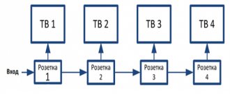
If the connection is to a network without a ground loop, then everything is much simpler. In this case, the sockets are connected with a cable. That is, the phase wire approaches the first, and is connected from it to the second by a jumper. Further, from the second jumper goes to the third. The neutral contacts of sockets are also switched in a similar way.
Installation of an internal socket
Installing an outlet is a job that almost anyone can handle if they follow safety rules. If we are not talking about replacing an old device, but about installing a new, internal one, then the master will need the socket itself, a socket box and a hammer drill, which will have to make a hole and grooves for the wiring. The installation box is selected depending on the wall. For concrete or brick, simple products are suitable; for drywall, you need socket boxes with clamps.
When the installation is carried out in a house where the electrical wiring has already been installed, the circuit breaker in the distribution panel is turned off before starting work. Then wait a while and check the absence of current with an indicator screwdriver. If the hole for the mounting box is made, then proceed to the installation of the socket box. The most reliable way is to use alabaster. First, the hole is moistened with water, then the box is fixed using an alabaster solution.
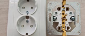
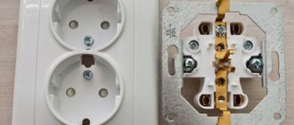
The conductor cores are stripped to 10 mm with a knife, then the contacts are fixed in the housing. To do this, loosen the central screws and insert the bare wires. The traditional arrangement is phase on the left, neutral on the right, grounding in its rightful place, if any. All contacts are tightened tightly with a screwdriver, but carefully: excessive zeal in this case can damage them.
The housing is fixed with spacer tabs and/or socket box screws, screwing in the screws as securely as possible. A decorative panel is installed and fastened on top, the fasteners are also tightened until they stop. After installation, the machine is turned on, the functionality of the socket is first checked with an indicator, then with any household appliance.
Precautionary measures
Since there is a possibility of electric shock when performing work, it is necessary to turn off the power to the apartment or house during electrical installation. This can be done using switches in the electrical panel. If the room has old-type wiring, you can turn off the power supply by unscrewing the plugs on the meter. Work on installing a socket box, when contact with live wires is excluded, is carried out without turning off the power, to allow the use of auxiliary power tools.
Attention! Before proceeding directly with electrical installation, you should make sure that the wires are actually de-energized. The check is carried out with an indicator screwdriver or tester.
Checking for voltage
Prices for voltage measuring instruments
Voltmeter
Installation in concrete or brick
As always, we start by preparing the tools, in this case we will need:
- If installation is carried out in concrete, a hammer drill is desirable; an impact drill is also suitable for working with brick.
- Screwdriver.
- A concrete bit, not to be confused with a drywall bit; if you try to make a hole last, it will instantly fail. Detailed information about crowns for concrete and brick can be obtained on our website.
Concrete crown
As an alternative, you can use a concrete drill; in this case, holes are drilled around the perimeter of the seat for the “glass”, then the excess material is knocked out. This option is quite labor-intensive; it can only be justified if you need to make one or two holes.
In addition, we will need plaster to make a solution for “freezing” the planting nests.
Algorithm of actions for installing a socket box for concrete:
- We install a crown attachment of the appropriate diameter on the hammer drill, and then drill a hole (A in Fig. 11). You need to prepare for the fact that this procedure is quite dusty, so you should take care to protect your eyes and respiratory organs with glasses and a respirator. To limit the spread of concrete dust, the room can be “sealed” using plastic film and mounting tape.
- We knock out the concrete (B), clean the hole (C) from dust.
- We prepare the mounting socket (break out the plug for the cable entry), then insert the wires into the “glass”.
- Mix the gypsum solution and coat the seat (D) with it, then insert the socket box (E) into it. Remove the squeezed out excess solution (F).
Installing a seat in concrete
After the gypsum solution has hardened, finishing work can begin. After their completion, we proceed to the second phase - installation of electrical points. Since the same built-in sockets are used for plasterboard, concrete and brick walls, the algorithm for their installation is no different. That is, it is produced similarly to the process described above with drywall, so it makes no sense to repeat it.
Installation of electrical outlets: detailed instructions for all types of residential buildings in Russia
I would like to draw your attention to the correct connection of the wire to the contact connections.
There is a hidden contradiction in this question:
- on the one hand, there is nothing complicated and everything is in plain sight, simple and intuitive:
- but even experienced electricians often make typical mistakes that create problems when operating a conventional screw clamp.
Connecting a wire under a screw involves a number of features that take into account:
- core metal (copper or aluminum):
- wire thickness;
- connection method (straight segment or ring).
How to choose a wire: copper or aluminum
The metal of the wire or cable plays an important role in creating electrical contact. It can be made of copper or aluminum.
Aluminum is soft , chemically resistant, but has increased resistance compared to copper. Its wire thickness of 2.5 mm sq. can transmit approximately the same loads as for copper of 1.5 sq. m.
In air, rapid oxidation of the aluminum surface occurs with the formation of an oxide film with insulating properties. It further deteriorates the electrical resistance of the contact point and causes it to overheat.
Copper is harder . It works better in stationary wiring with a single-wire monolithic core. Flexible stranded wires are designed for installation in moving mechanisms. But it is permissible to lay them inside the apartment.
The connection of copper stranded conductors to the contacts of sockets and switches must be done through terminations - special tips that require additional crimping.
Simple twisting will lead to some of the cores coming out of contact, and under extreme load it will begin to overheat. It is permissible to solder the twist well, but this is a complex process.
Selection of cable cross-section by load: table
The thickness of the wire must correspond to the power transmitted through it. It is convenient to evaluate it using the proposed table.
The diameter of the cable conductor can be easily measured with a regular ruler. To do this, take a pencil or any round cylindrical object. The insulation is removed from a piece of wire.
Then the wire is wound in tight rings of 10-15 turns onto this cylinder and pressed with pliers. All that remains is to use a ruler to measure the total height of the created spring and divide by the number of turns. We get the diameter. Using it we calculate the area of the circle through the number π=3.14.
How to connect a wire to an outlet: 2 ways
Create a contact using a ring
In Soviet models of plugs and sockets, it was often necessary to roll the monolithic core into a ring and install it into the terminal with a screw clamp. Since this method is still used, I point out a typical mistake that is made due to inattention.
The fact is that when screwing the screw, the locking washer transmits the rotational force of the screwdriver to the ring and slightly deforms it: compresses or unclenches it.
Therefore, the ring should be put on the screw in the direction of the thread movement. Then it will begin to shrink and form a tight electrical contact. Don't forget to place a washer under the screw. Otherwise, the head will simply push the ring apart.
This requirement is especially relevant when working with aluminum wiring. Soft metal easily moves under external load, although I often came across copper rings with loose contact on relay panels.
Modern way of connection
Now all plugs and sockets are made to make the work of installers easier. From the small tip of the wire, it is enough to remove a little insulation and insert it into the prepared socket, then press it with a fixing screw through the washer.
This technique makes installation easier, but requires maintaining the clamping force. I think that in principle the method is normal, but it is not very suitable for connecting aluminum wires.
The fact is that at maximum load, copper and aluminum heat up and expand in the volume clamped by the screws. It doesn't happen the same way. Metals have different linear expansion coefficients.
Aluminum expands more. Due to its limited volume and high plasticity, it changes its shape. And after the load is turned off, it cools down and decreases in size. In this case, the compression force of the screw decreases.
After several cycles of intense loads, the wire clamp in the contact socket may disappear. In addition, a layer of oxide film appears on aluminum when exposed to air.
All this creates increased electrical resistance of the contact and overheating of the structure, damage to the insulation.
Aluminum wiring requires more frequent monitoring of the technical condition of contact connections, regular internal inspection and careful compression.
Copper wire has less linear expansion and increased mechanical strength. It works better in contact connections of plugs, sockets and switches.
After assembling the electrical circuit and conducting an internal inspection, all its elements and contacts must be tested under load during the operating time of the household appliance.
As soon as the voltage is removed from the equipment, the heating of the contact connections should be immediately assessed and inspected. This stage allows you to identify any hidden defects and accidental installation errors.
Classification, features and sizes of socket boxes
Depending on the material of the surface where the installation will be carried out, mounting sockets are divided into two types:
- Under drywall.
- For concrete and brick.
Socket boxes: for plasterboard (A) and concrete or brick (B)
The differences between these types are that the first are fixed using special ears (marked with red circles in Figure 3), and the second are “frozen” into the wall with gypsum mortar.
In addition, “glasses” can be single or composite. The first (they are shown in Figure 3) are used for single structures, the second - for a group of sockets.
Composite socket boxes for plasterboard (A) and concrete or brick (B)
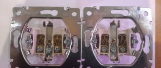
If you plan to install two electrical points, then it makes sense not to drill a second hole for the socket box, but to choose a double socket design. This is especially true when installation is carried out on a concrete surface.
Double socket design for installation in one socket box
As for the material, plastic is used for concrete, brick and plasterboard surfaces; if hidden installation is carried out in a combustible base, then it is necessary to use metal socket boxes.
Concluding the topic of landing sockets, we present their standard sizes; this information will be useful both at the design stage and during installation work.
Typical sizes of socket boxes
Having finished with the theory, let's move on directly to the installation process. Let's start from simple to complex.
Briefly about retractable sockets
In the article we did not pay attention to this type of electric point. This concept has only recently been introduced to the market, but is nevertheless quickly gaining popularity.
Retractable socket built into the tabletop
Structurally, such devices are much more complex than standard products, and accordingly their cost is much higher. The factor of novelty also has an important influence on the price. In the near future, an overview of these devices will be presented on our website, including information on how to install a socket of this type.
The eternal question: install socket boxes before or after plastering
If the surface is covered with plasterboard, there is no such problem. What to do when installing socket boxes in a brick or concrete wall?
In fact, from a technical point of view there is no difference. You can accurately calculate the planting height: the main thing is that the socket box does not stick out, even by 1 mm. If the edge is recessed by 3–5 mm, this is not a problem. The mounting pad of the socket will rest against the wall, and use longer screws for fastening.
The problem is rather psychological - it’s a shame to drill into a plastered surface.
When choosing a sequence (before or after plastering), one nuance should be taken into account: if the edge of the installed socket boxes protrudes above the plane of the wall, how will you apply the plaster evenly?
Therefore, the best option is to drill out niches, then plaster the walls (there will be holes for sockets with uneven edges), and then carefully clean the edges of the holes. Before installing the socket boxes, you will have to restore the markings.
Next - nothing new. We mount the socket boxes on alabaster and wait until it dries. All that remains is to trim the edges a little.
Simple advice for beginning craftsmen: To prevent alabaster or plaster from hardening too quickly, add PVA glue to the water. After mixing, the solution takes 2–3 times longer to crystallize.
True, you will have to wait several hours for final drying. But the mixture will be many times stronger.
Types of sockets by type of connectors
There are at least 12 types of socket plugs that are used in different countries. This classification was proposed by the US government and has been adopted by most other countries.
Type A. Initially, the standard for this outlet was adopted in the USA, and then it was picked up by 38 other countries. It has two flat rectangular contacts arranged in parallel. There is no grounding conductor here. Such sockets can still be seen in old buildings, as they are compatible with the plugs of modern electrical equipment. However, they practically never appear on sale.
Type B. This is an improved Type A with the addition of a ground pin. If you bought a household appliance from the USA, then it will probably have a plug that fits such an outlet. In addition to the USA, this type is also used by Mexico, Venezuela, Canada, Colombia and other countries.
Type C. This is the type most familiar to us since the times of the USSR. It consists of two round contacts located in parallel, without grounding. This type of socket is used in most countries in Europe and the Middle East. Although with the advent of type F models it gradually begins to die out.
Type D. An obsolete type of sockets, introduced at one time by the British in countries that were former colonies of England. Such sockets can very rarely be found in old English houses, as well as in India.
Type E. Modern standard adopted in France. It differs from type C by the presence of a ground located above the contacts. Such sockets are widespread in France, Belgium, Poland, the Czech Republic and Slovakia. Sometimes they can be found on the territory of modern Russia.
Type F. This is the most common European standard of sockets in our country with two conductive contacts and two grounding contacts located at the bottom and top. Such sockets first appeared in Germany and became known as “Shuko” (“protective contact”). The size of the current-carrying contacts in the device here is slightly larger than in Type C models, so some old Soviet thin plugs may not fit tightly into the socket.
Type G. This standard was introduced by the British and involves the use of plugs with a fuse inside them. You can also use Euro plugs through an adapter, but the adapter must have a fuse (ground contact). This type of outlet is most widespread in Ireland.
Type N. An exclusively Israeli version of sockets, in which three contacts form the letter “Y”. Until 1989, products with flat contacts (as in the figure) were used, but now they are mainly with round ones. Unfortunately, there are no adapters for plugs for such sockets (although in China they are probably already in development) for other types of sockets, so buying Israeli household appliances and using them in our country is a problematic task.
Type I. This is an Australian standard and is also used in New Zealand, Fiji and Papua New Guinea. Two current-carrying contacts are located at an angle, and at the bottom there is a ground contact. If you suddenly go on a trip around the world and find yourself in these countries, be sure to get an adapter.
Type J. Standard adopted by Switzerland. It is somewhat similar to type C, only the grounding contact is located between the current conductors and is slightly lowered down. Euro plugs can be used with it without any adapters.
Type K. Danish type of sockets. The difference from the French standard is only in the location of the grounding contact, which is installed directly in the plug of the device.
Type L. A standard that is common in Italy. It is compatible with type C Euro plugs, so modern electrical appliances can be safely connected to Italian sockets. The middle contact is grounding.
“Half” sockets can be found in modular series (and install 2 pieces in one post!)
Single-module flat electrical socket LK45
Yes. It turns out there are also “flat” sockets. I mean, sockets for a flat plug. Advantage: you can connect two devices to a “single outlet” without additional devices. The downside is that there are only flat plugs, and when you turn them on: no charger, no Euro-Schuko plugs. In the picture: a “flat socket” module from the LK45 series.
How much does it cost?
Prices and descriptions for all Florence electrical installation products can be found in the product cards in the “Product Catalog” section. Here are product cards for a single socket with protective curtains and a similar socket without protective curtains (prices for sockets depend on the colors, white and beige sockets are a little cheaper, gray and black are a little more expensive).
The difference in price for a single socket with protective shutters and without protective shutters in the Florence series of electrical installation products is about 16%. If there are small children in the apartment, then we definitely recommend installing sockets with protective curtains.
Home safety and protection
Adults, trying to protect small children, install sockets with protective devices. Today, stores have a wide range of products, including both silicone protective pads and special devices that operate automatically (touch sockets).
Such devices reduce the likelihood of death in the event, but it is worth remembering that even a high-quality child-resistant outlet does not provide a 100% guarantee that the baby will not harm himself. Therefore, the main rule, in addition to installing special devices, is control of the child himself.