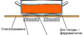
An induction cooker is capable of heating metal cookware through induced eddy currents from a high-frequency magnetic field.
The standard circuit of an induction cooker is usually represented by an induction coil and a frequency converter, as well as an electronic control unit equipped with temperature sensors.
Introduction
Induction cookers are relatively new equipment, but already extremely popular among domestic consumers.
A special feature of such stoves is their ability to heat only the bottom of the cookware.
In conventional electric stoves, the burner that is turned on initially heats up.
Before choosing such equipment, it is important to familiarize yourself with the advantages of operation, as well as take into account some of the design disadvantages of an induction cooker.
The main advantages are presented:
- faster heating and cooking process, which takes several times less time than when using a traditional electric stove;
- no burning of food that may fall on the hob during cooking, which is due to the low temperature of the burner;
- reduction in electrical energy consumption due to very rapid heating of the kitchen utensils used;
- ease of use due to the ability to adjust the cooking mode on different stoves.
The advantages also include safety of operation, which is especially important for families with small children, pensioners or people with disabilities.
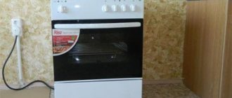
Induction cooker in the kitchen
Operating disadvantages in such modern equipment are also present and, despite the fact that they are minimal, they should be taken into account when choosing a model:
- turning on induction equipment at full power can create an increased load on the electrical network;
- for cooking on this type of stove, only special kitchen utensils with a ferromagnetic bottom should be used;
- Some models are characterized by the presence of a single high-frequency generator, which adversely affects the power level when all burners are turned on simultaneously;
- The hob surface is fragile, so during the entire period of operation it is necessary to exercise some caution.
As practice shows, the operation of models belonging to the economy class price category is often accompanied by irritating noise and a kind of humming.
It is important to remember that induction cookers are capable of creating fairly high electromagnetic radiation and can have a negative effect on household appliances installed at a short distance.
Opening
To open the induction cooktop, eight Phillips screws had to be removed. After removing them, the plastic case is divided into two parts. The first part, the top, includes the user interface and associated electronics. The lower part is a glass hob. These two parts are connected by a five-wire ribbon cable (loop).
Hob with top removed
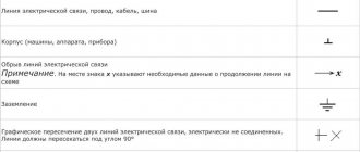
Induction cooker diagram
In accordance with the heating circuit, the electric current that flows from the electrical network to the coil undergoes a transformation into a magnetic field that generates eddy currents.
As a result of the interaction of the ferromagnetic bottom with the induction current, a circuit is formed, and the resulting thermal energy warms up the kitchenware used and its contents.
The glass-ceramic surface of the stove covers an induction coil with an electric current flowing at a frequency of 50 kHz. The standard equipment layout is relatively complex, and can have very significant differences depending on the model. The basis is represented by a generator, a driver using medium-power transistors and an output bipolar transistor, which has an insulated gate and controls the inductor coil.
The operation scheme of an induction cooker is reflected in the maintenance rules and operating features of such equipment, and must also be taken into account when choosing kitchenware, which must be made of special materials with ferromagnetic properties.
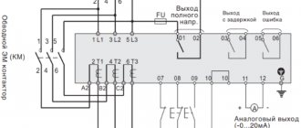
Electrical diagram of an induction cooker
The most complex structural element is the electronic control unit, through which it not only turns on, but also regulates the power level of the generator. Modern models are characterized by the presence of an infrared sensor device that effectively controls the cooking process. After the cookware is removed from the hob, the stove automatically turns off.
You cannot use copper, glass, ceramic or aluminum cookware, and the surface of an induction cooker can only be cleaned using special products that do not have abrasive effects.
User Interface Electronics
User Interface Circuit Board
These electronics allow the user to control the cooktop. The user interface electronics consists of a printed circuit board with all the user interface elements located on it. This board contains seven 5mm red LEDs, six tactile buttons and a seven-segment display. The board has pads for two additional buttons and two more LEDs, but they are empty.
1628 LED Driver
On the back of the board there is a “1628” LED driver. The 1628 LED driver is made by several companies and can do much more than just drive LEDs. The 1628 converts serial data to control individual LEDs and allows button scanning. This driver is housed in a SOP 28 package and is soldered to the back of a single-layer PCB.
User Interface Printed Circuit Board. Side with components
The PCB has several other passive elements located on top. These components perform logic level conversion using voltage dividers and help filter signals.
DIY making
The power circuit of a standard induction cooker can vary significantly depending on the design features of the modification, but most often it is presented:
- a ferrite torus, which is placed on the network wire and suppresses common-mode interference;
- standard fuse;
- a capacitor that filters impulse noise that occurs during operation;
- a resistor that is activated after the mains power is turned off;
- a rectifier designed for power ratings and effectively protecting the device from overvoltage;
- wire shunt;
- filtering system for impulse noise;
- a capacitor that allows you to return energy from the oscillatory-inductor circuit to the intermediate part with constant current values;
- a resonant capacitor that provides continuous current after the transistor is blocked;
- an induction device, which is focused on transferring heat from the surface to the bottom of the kitchenware used;
- a transistor that converts direct current into variable indicators;
- a resistor to fix the transistor after disconnection;
- a resistor to suppress high-frequency current indicators;
- rectifier for voltage in the electrical network;
- a current controller that prevents the possible occurrence of an overload;
- collector voltage controller.
Budget models contain only basic structural elements, which affects the functionality of such a device.
Self-manufacturing of a simple induction cooker requires strict adherence to all standards, which will make the operation of such a device completely safe. A significant difficulty in the process of constructing a stove arises at the stage of selecting high-quality material to create the base of the hob.
DIY induction cooker - diagram
Such a material must be distinguished by the ability to correctly conduct electromagnetic radiation, not conduct current, and withstand high temperatures.
Factory-made household cooking equipment, which includes all modern induction cookers, is made using quite expensive ceramics.
It is for this reason that making your own induction hob at home is associated with certain problems in choosing a worthy alternative to a ceramic surface.
A heat gun is good because it quickly distributes heat. Making a heat gun with your own hands is quite simple.
You will learn how to calculate heat loss at home from this information.
Recommendations for making a pellet burner with your own hands can be found here.
Control electronics
Special microcontroller
The heart of this device is a special microcontroller S3F84B8 from Zilog. This microcontroller is designed for use in induction hobs!
This microcontroller has several features that make it beneficial to use here. It is equipped with a 10-bit PWM channel for coil switching and eight 10-bit analog-to-digital converters. It requires only a few external components, which reduces the cost of the bill of materials.
Safety for humans
Recently, there have been many different discussions about the level of harm of induction cookers. The operating principle of such products is based on electromagnetic fields, the negativity of which is well known to everyone. Experts have proven that at a distance of 2 cm from the stove, radiation is always higher than the permissible norm. If the pan is offset relative to the center of the burner, then the indicated norm will be overestimated in the area of 15 centimeters from the hob.
If it doesn't turn on at all
If the equipment does not turn on at all, check the voltage immediately. If the voltage is low, the hob may not turn on. To avoid such situations in the future, it is advisable to install a stabilizer. This will significantly extend the life of the equipment, since electronics are very sensitive to power quality, and electronics are the most difficult to repair (and more expensive).
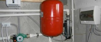
If the voltage is normal, we will continue repairing the hob by inspecting the power cord. Oddly enough, many breakdowns are associated with its damage - frayed, bent, crushed, insulation burst/melted, etc. First, we inspect the cord (disconnecting it from the network), then we check for the integrity of the wires and for insulation breakdown (each wire to the ground and to each other).
What to do if the hob does not turn on? First of all, check the cord and contacts
The next step is to check the contact in the terminal block. A loose or oxidized contact can also cause the hob to not turn on. What to do in this case? Unscrew the contact, clean it from oxides, and tighten it well again.
If the stove still shows no signs of life, find the fuse. It stands at the entrance, burns out during power surges - to protect more expensive parts from damage. It can look different, but most often it is a glass or ceramic tube with metal caps on the edges. Some types of fuses are shown in the photo below. There may be such options.
Types of fuses
We found the fuse, then take a multimeter and measure its resistance. It should be small. If the device shows an open circuit (infinitely high resistance), the fuse has blown. Another way is to put the multimeter in test mode and touch the probes to both ends of the fuse. The device is silent - it has burned out.
We take out the blown fuse and replace it with a similar one. Exactly a similar one - with the same parameters (indicated on the case). It is not recommended to install a “bug” or one with less sensitivity - with the next power surge the breakdowns will be much more serious.
The only easy check left is to check whether the power is reaching the control unit from the terminal block. Maybe the wiring is damaged or the contact is loose/lost somewhere. Do this again using a multimeter. We check the wires for integrity (you can test them, you can measure the resistance) and the presence of insulation breakdown (on the body and between each other). If all parameters are normal, you can turn on the power and carefully measure the voltage at the input of the control unit. The voltage is normal, but the hob still does not turn on - the problem is in the control unit. Further repairs to the hob are related to this unit.
The hob is one of the most important appliances in the kitchen, and like any other equipment, it is susceptible to breakdowns, but it’s quite easy to repair it yourself. If a malfunction is discovered during the warranty period, your stove will be repaired free of charge. But if the breakdown occurs several years later, you can try to repair the hob yourself, since contacting specialists may cost little less than buying a new stove.
In this article, our specialists have listed all the malfunctions of hobs and step-by-step disassembled the process of repairing faults with their own hands.
Read also: How to find out the type of light bulb base
Coil
Induction Coil
The key part of an induction hob is the coil. The coil in this induction cooktop consists of 21 turns of Litz wire. Litz stranded wire is used to reduce the skin effect.
Litz wire
In the middle of the induction coil there is a temperature sensor. This sensor consists of two temperature-sensitive components. The first is a thermal fuse. This fuse is designed to break at 184°C or 363°F.
The second component is a zener diode. Because of their temperature coefficients, some zener diodes can be used to measure temperature by observing their reverse breakdown voltage.
Temperature sensors
Choosing a quality model
The circuit of a tabletop induction cooker is designed in such a way that everything depends on the voltage level in the house. If the readings are below the required values, then the main fuse near the distribution panel will regularly be knocked out, and the power cord will also burn out.
If the consumer understands that problems with voltage are still present, then it is better to study the circuit of the Endever induction cooker of lower power, which is equipped with a function for self-adjusting the required indicators. This is the simplest and most affordable option. But the heating rate of the installed container will be reduced. After purchasing the product, you need to lay the cable yourself with the appropriate cross-section. For safety, a separate circuit breaker with a suitable current rating can be installed.
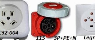
Connecting a panel without a plug
If a socket protruding a few centimeters does not suit you and you want to carefully hide everything in a socket box or junction box, then you can do this in two ways:
- through GML sleeves
- through the mounting box KlK-5S
First, let's decide on the wires. On many models, a connected cable already comes out of the panel, but it has 4 cores. And you only have three in your socket. What should I do?
The fact is that such hobs are simultaneously designed for both a single-phase 220V connection and a two-phase 380V connection. In this case, one half of the burners will operate from one phase 220V, and the other from the second.
Some people believe that the second phase is only used for control power. This is wrong. Power is distributed evenly across both phases. To connect the whole thing to the usual 220 Volts, simply remove one core to the side and insulate it.
What remains is zero (usually a blue wire), ground (yellow-green) and phase (brown, black or another color).
You can combine two phase wires into one through a lug. For example, in many Bosch panels, where the cable is not removable, this is how it was originally done.
There is also an option with a 5-core cable. Such panels are usually of high power from 7 kW and above. They are initially designed for 380V. To connect them to a 220V network, you need to connect two wires in pairs.
For example, connect the black and brown wires to phase, and the blue and gray wires to zero. The earth yellow-green remains single.
But if you strictly follow the rules, then such a connection is not entirely correct. Since the protective conductor PE must be of the same cross-section as the phase conductors. And yours will be twice as thin.
Types of faults
Recently, the Galaxy GL 3054 induction cooker has become the most popular. The repair scheme for this product is distinguished by its simplicity and affordability, due to which users do not need to spend a large amount to restore the functionality of the unit. The most common faults include:
- There is no response to the touchpad. If there is grease on the surface, the system may simply not recognize human touch. To solve this problem, it is enough to carefully clean the surface.
- Several burners do not work. You need to check the connection of the stove to the power source. Overheating may damage the inductor connector.
- The cooling fan does not turn off. The cause may be a malfunction of the temperature sensor.
- The stove does not respond to dishes. For cooking, you can only use pots and pans that were originally intended for such cooking surfaces. Otherwise, you need to check the power supply and temperature sensor.
- The residual heat indicator is not displayed. Most often, the situation arises against the background of a breakdown of the temperature sensor. When replacing the device, you need to check that the connecting wiring is securely connected to avoid a possible fire.