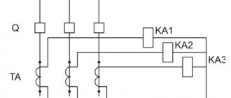
Why do you need engine protection?
In order to avoid unexpected failures, costly repairs and subsequent losses due to motor downtime, it is very important to equip the motor with a protective device.
Engine protection has three levels:
- Built-in motor protection with overheat protection to avoid motor damage and malfunction. Built-in protection always requires an external switch, and some types of built-in motor protection even require an overload relay.
- External overload protection, i.e. protection against overload of the pump motor, and, consequently, prevention of damage and malfunction of the electric motor. This is current protection.
- External short circuit protection of the installation. External protection devices are usually fuses of various types or short-circuit protection relays. Safety devices of this type are mandatory and officially approved; they are installed in accordance with safety regulations.
Overload is the cause of about 30% of electric motor failures. Source: US Electrical Engineering Research Association
Ultrasonic motor protection devices manufactured by NTK Priborenergo
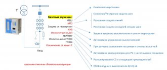
NTK Priborenergo offers electric motor protection devices of its own production. The equipment is manufactured with quality control at all stages of production and has a long service life. Devices UZD-1, UZD-2 and UZD-3 protect the asynchronous electric motor by controlling switching equipment. The rated current of the protected electric motor is up to 10 A (UZD-1), from 10 to 100 A (UZD-2) and over 100 A (UZD-3).
In addition to the standard ones, the equipment has additional functions:
- current control, as a function of the load on the shaft, with motor shutdown for mechanisms in stopping mode,
- protective shutdown according to specified technological parameters.
- thermal protection of the engine (if there are sensors),
Ultrasound devices produced by NTK Priborenergo are equipped with information outputs for communication with a controller or PC.
Ultrasound connection diagram
Possible Engine Failure Conditions
During operation, various malfunctions may occur. Therefore, it is very important to foresee the possibility of failure and its causes in advance and protect the engine as best as possible. The following is a list of failure conditions under which motor damage can be avoided.
- Poor quality of power supply:
- high voltage;
- low voltage;
- unbalanced voltage/current (spikes);
- frequency change.
- Incorrect installation, violation of storage conditions or malfunction of the electric motor itself.
- A gradual increase in temperature and its exit beyond the permissible limit:
- insufficient cooling;
- high ambient temperature;
- low atmospheric pressure (work at high altitudes above sea level);
- high temperature of the working fluid;
- too high viscosity of the working fluid;
- frequent switching on/off of the electric motor;
- Load moment of inertia is too high (different for each pump).
- rotor blocking;
- phase failure.
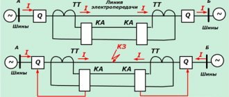
To protect the network from overloads and short circuits when any of the above failure conditions occur, it is necessary to determine which network protection device will be used. It should automatically turn off power from the network. A fuse is a simple device that performs two functions. As a rule, fuses are connected to each other using an emergency switch, which can disconnect the motor from the power supply. In the following pages we will look at three types of fuses in terms of their operating principle and applications: fuse switch, fast-blow fuses and time-lag fuses.
Fusible safety switch
A safety switch is an emergency switch and a fuse combined in a single housing. A switch can be used to open and close a circuit manually, while a fuse protects the motor from overcurrent.
Switches are typically used in connection with maintenance work when it is necessary to interrupt the current supply.
The emergency switch has a separate casing. This cover protects personnel from accidental contact with electrical terminals and also protects the switch from oxidation.
Some emergency switches are equipped with built-in fuses, other emergency switches are supplied without built-in fuses and only have a switch.
The overcurrent protection device (fuse) must distinguish between overcurrent and short circuit. For example, minor short-term overcurrents are quite acceptable. But if the current increases further, the protection device must operate immediately. It is very important to prevent short circuits immediately. A fused switch is an example of a device used for overcurrent protection. Properly selected fuses in the switch open the circuit during current overloads.
Fast-blow fuses
Fast-blow fuses provide excellent short-circuit protection. However, short-term overloads, such as motor starting current, can cause this type of fuses to break. Therefore, fast-blow fuses are best used on circuits that are not subject to significant transient currents. These fuses typically carry about 500% of their rated current for one-fourth of a second. After this time, the fuse insert melts and the circuit opens. Therefore, in circuits where the inrush current frequently exceeds 500% of the fuse rating, fast-blow fuses are not recommended.
Time delay fuses
This type of fuse provides both overload and short circuit protection. Typically, they allow 5 times the rated current for 10 seconds, and even higher current values for shorter periods. This is usually enough to keep the motor running and prevent the fuse from opening. On the other hand, if overloads occur that last longer than the melting time of the fuse element, the circuit will also open.
Fuse response time
The fuse operating time is the time it takes for the fuse element (wire) to melt for the circuit to open. Fuses have an operating time that is inversely proportional to the current value - this means that the greater the overcurrent, the shorter the period of time for the circuit to trip.
In general, we can say that pump motors have a very short acceleration time: less than 1 second. In this regard, time-delay fuses with a rated current corresponding to the full load current of the electric motor are suitable for electric motors.
The illustration on the right shows the principle of generating the fuse response time characteristic.
The x-axis shows the relationship between actual current and full load current: if the motor draws full load current or less, the fuse will not open. But at a current value 10 times the full load current, the fuse will open almost instantly (0.01 s). The y-axis shows the response time. During starting, a fairly large current passes through the induction motor.
In very rare cases this results in shutdown via relays or fuses. To reduce the starting current, various methods of starting an electric motor are used.
Operating principle of the device
Performing a protective function, the circuit breaker disconnects the power supply circuits. A thermal relay differs from it in that when the load is exceeded, it simply issues a control signal. With such protection, small currents are switched in one control circuit.
In the circuit in front of the thermal relay there is a magnetic starter. When the circuits are opened in an emergency, there is no need to duplicate the operation of the contactor. Consequently, no material is consumed for the manufacture of power contact groups.
The most popular are devices equipped with bimetallic plates. The plate itself consists of two similar elements.
One of them has a significant temperature coefficient, while the other has a slightly smaller one. These two components fit tightly together.
Since the components of a bimetallic strip are made of a pair of dissimilar metals having unequal expansion coefficients, heating causes it to bend and interact with the contacts
Such rigid fastening is ensured by welding or hot rolling. Due to the fact that the plate is fixed motionless, when heated, it bends towards the element with a lower temperature coefficient. This principle is taken as the basis when creating thermal relays.
In their production, chromium-nickel steel and non-magnetic steel are used, which have a high temperature coefficient. Invar, a compound of nickel and iron, is used as a material with a low value of this parameter.
A thermal relay operates according to this scheme. The loose end of the bimetallic plate, when it bends, affects the contacts of the thermal relay (+)
The bimetal plate is heated by load currents. They most often flow through a special heater. There is also combined heating, in which, in addition to the heat given off by the heater, the bimetal is also heated by the current passing through it.
What is a circuit breaker and how does it work?
An automatic current switch is an overcurrent protection device. It automatically opens and closes the circuit at a preset overcurrent value. If the current switch is used within the range of its operating parameters, opening and closing does not cause any damage to it.
Immediately after an overload occurs, you can easily resume operation of the circuit breaker - it is simply reset to its original position.
There are two types of circuit breakers: thermal and magnetic.
Thermal circuit breakers
Thermal circuit breakers are the most reliable and economical type of protective devices suitable for electric motors. They can withstand the large current amplitudes that occur during motor starting and protect the motor from faults such as locked rotor.
Magnetic circuit breakers
Magnetic circuit breakers are accurate, reliable and economical. The magnetic circuit breaker is resistant to temperature changes, i.e. Changes in ambient temperature do not affect its operating limit.
Compared to thermal circuit breakers, magnetic circuit breakers have a more precisely defined response time. The table shows the characteristics of two types of circuit breakers.
The circuit breaker is a protective device against overcurrent. It automatically opens and closes the circuit at a preset overcurrent value. The circuit is then automatically or manually closed
Operating range of circuit breaker
Automatic circuit breakers differ in the level of operating current. This means that you should always select a circuit breaker that can withstand the highest short circuit current that may occur in a given system.
Overload relay functions
Overload relay:
- When starting the electric motor, they allow you to withstand temporary overloads without breaking the circuit.
- The electric motor circuit is opened if the current exceeds the maximum permissible value and there is a risk of damage to the electric motor.
- They are reset to their original position automatically or manually after the overload has been eliminated.
IEC and NEMA standardize trip classes for overload relays.
Trigger class designation
Typically, overload relays respond to overload conditions according to their tripping characteristics. For any standard (NEMA or IEC), the division of products into classes determines how long the relay requires to open when overloaded. The most common classes are: 10, 20 and 30. The digital designation reflects the time required for the relay to operate.
A Class 10 overload relay operates in 10 seconds or less at 600% full load current, a Class 20 relay operates in 20 seconds or less, and a Class 30 relay operates in 30 seconds or less.
The angle of inclination of the response characteristic depends on the protection class of the electric motor. IEC motors are usually tailored to a specific application. This means that the overload relay can handle excess current that is very close to the relay's maximum capacity. Class 10 is the most common class for IEC motors. NEMA motors have a larger internal capacitor, so Class 20 is more commonly used.
Class 10 relays are typically used for pump motors, as the acceleration time of electric motors is about 0.1-1 second. Many high inertia industrial loads require a Class 20 relay to operate.
Operating time is the time it takes for a relay to operate during an overload period. The response time is divided into classes.
Combination of fuses with overload relays
Fuses serve to protect the installation from damage that may be caused by a short circuit.
For this reason, fuses must have sufficient capacity. Lower currents are isolated using an overload relay. Here, the rated current of the fuse does not correspond to the operating range of the electric motor, but to the current that can damage the weakest components of the installation. As mentioned earlier, a fuse provides short circuit protection but not low current overload protection.
The figure on the right shows the most important parameters that form the basis for the coordinated operation of the fuses in combination with the overload relay.
It is important that the fuse blows before other parts of the installation suffer thermal damage from the short circuit.
The most important parameters that form the basis for the coordinated operation of fuses in combination with the overload relay. The time/current characteristic of the fuse must always be below the thermal damage limit characteristic (red)
Internal protection built into windings or terminal box
Why do you need built-in motor protection if the electric motor is already equipped with an overload relay and fuses? In some cases, the overload relay does not detect motor overload. For example, in situations:
- When the motor is closed (insufficiently cooled) and slowly heats up to a dangerous temperature.
- At high ambient temperatures.
- When the external motor protection is set to trip current too high or is not installed correctly.
- When a motor is restarted several times within a short period of time, the starting current heats up the motor, which can ultimately damage it.
The level of protection that internal protection can provide is specified in IEC 60034-11.
Designation TP
TP is an abbreviation for thermal protection. There are different types of thermal protection, which are designated by the code TP (TPxxx). Code includes:
- The type of thermal overload for which the thermal protection was designed (1st digit).
- Number of levels and type of action (2nd digit).
- Category of built-in thermal protection (3rd digit).
In pump motors, the most common TP designations are:
- TP 111: Gradual overload protection.
- TP 211: Protection against both rapid and gradual overload.
Illustration of the permissible temperature level when the electric motor is exposed to high temperatures. Category 2 allows higher temperatures than Category 1.
All Grundfos single-phase motors are equipped with motor current and temperature protection in accordance with IEC 60034-11. The type of motor protection TP 211 means that it responds to both gradual and rapid temperature increases. The device is reset and returned to its initial position automatically. Grundfos MG three-phase electric motors with power from 3.0 kW are equipped as standard with a PTC temperature sensor. These motors have been tested and approved as TP 211 motors, which respond to both slow and rapid temperature rises. Other electric motors used for Grundfos pumps (MMG models D and E, Siemens, etc.) can be classified as TP 211, but as a rule they have protection type TP 111. The data on the manufacturer's data sheet must always be observed. sign. Information about the type of protection of a particular motor can be found on the nameplate - marking with the letter TP (thermal protection) according to IEC 60034-11. Typically, internal protection can be provided using two types of protection devices: Thermal protection devices or thermistors.
Thermal protection devices built into the terminal box
Thermal protection devices, or thermostats, use a bimetallic, instantaneous dial-type circuit breaker to open and close a circuit when a certain temperature is reached. Thermal protection devices are also called “klixons” (after a trademark from Texas Instruments). Once the bimetallic disk reaches a predetermined temperature, it opens or closes a group of contacts in the connected control circuit. Thermostats are equipped with contacts for either normally open or normally closed operation, but the same device cannot be used for both modes. Thermostats are pre-calibrated by the manufacturer and their settings cannot be changed. The discs are hermetically sealed and located on the contact block.
The thermostat can supply voltage to the alarm circuit if it is normally open, or the thermostat can de-energize the motor if it is normally closed and connected in series with the contactor. Since the thermostats are located on the outer surface of the ends of the coil, they react to the temperature at their location. When applied to three-phase motors, thermostats are considered unstable protection under braking conditions or other conditions of rapid temperature change. In single-phase electric motors, thermostats serve to protect against blocked rotor.
Thermal circuit breaker built into the windings
Thermal protection devices can also be built into the windings, see illustration below.
Thermal protection built into the windings. Thermal circuit breakers, sensitive to changes in current and temperature.
They act as a mains switch for both single-phase and three-phase electric motors. For single-phase motors up to 1.1 kW, the thermal protection device is installed directly in the main circuit to act as a winding protection device. Klixon and Thermic are examples of thermal circuit breakers. These devices are also called PTO (Protection Thermique a Ouverture).
Indoor installation
Single-phase motors use one single thermal circuit breaker. In three-phase electric motors there are two series-connected switches located between the phases of the electric motor. Thus, all three phases are in contact with the thermal switch. Thermal circuit breakers can be installed at the end of the windings, but this results in longer response times. The switches must be connected to an external control system. This protects the electric motor from gradual overload. For thermal circuit breakers, a relay amplifier is not required.
Thermal switches DO NOT PROTECT the motor when the rotor is locked.
Design of thermal relays
Thermal relays of all types have a similar device. The most important element of any of them is the sensitive bimetallic strip.
The operating current value is influenced by the temperature of the environment in which the relay operates. An increase in temperature reduces the response time.
To minimize this influence, device developers choose the highest possible bimetal temperature. For the same purpose, some relays are equipped with an additional compensation plate.
The device consists of a housing, a nichrome heater, a bimetallic plate, a latch, a screw, a lever, a moving contact and a return button (+)
If nichrome heaters are included in the relay design, they are connected in a parallel, series or parallel-series circuit with a plate.
The current value in the bimetal is regulated using shunts. All parts are built into the body. The U-shaped bimetallic element is fixed on the axis.
A coil spring rests against one end of the plate. The other end is based on a balanced insulating block. It rotates around an axis and is a support for a contact bridge equipped with silver contacts.
To coordinate the setting current, the bimetallic plate is connected at its left end to its mechanism. The adjustment occurs due to the influence on the primary deformation of the plate.
If the magnitude of the overload currents becomes equal to or greater than the settings, the insulating block rotates under the influence of the plate. When it is tipped over, the device's normally closed contact is switched off.
TRT thermal relay in section. Here the main elements are: housing (1), setting mechanism (2), button (3), axis (4), silver contacts (5), contact bridge (6), insulating block (7), spring (8), plate bimetallic (9), axle (10)
The relay automatically returns to its original position. The self-return process takes no more than 3 minutes from the moment the protection is turned on. A manual reset is also possible; a special Reset key is provided for this.
When using it, the device takes its original position in 1 minute. To activate the button, turn it counterclockwise until it rises above the body. The installation current is usually indicated on the panel.
Operating principle of thermal circuit breaker
The graph on the right shows resistance versus temperature for a standard thermal circuit breaker. Each manufacturer has its own characteristics. TN usually lies in the range of 150 - 160 °C.
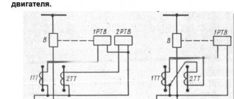
Connection
Connection of a three-phase electric motor with built-in thermal switch and overload relay.
TP symbol on the chart
Protection according to IEC 60034-11: TP 111 (gradual overload). In order to provide protection when the rotor is blocked, the electric motor must be equipped with an overload relay.
Thermistors built into windings
The second type of internal protection is thermistors, or positive temperature coefficient (PTC) sensors. Thermistors are built into the windings of the electric motor and protect it when the rotor is blocked, prolonged overload and high ambient temperatures. Thermal protection is provided by monitoring the temperature of the motor windings using PTC sensors. If the winding temperature exceeds the shutdown temperature, the sensor resistance changes according to the temperature change.
As a result of this change, the internal relays de-energize the control circuit of the external contactor. The electric motor cools down, and the acceptable temperature of the electric motor winding is restored, and the sensor resistance drops to its original level. At this moment, the control module is automatically reset to its original position, unless it has previously been configured to reset the data and turn it on again manually.
If the thermistors are installed at the ends of the coil themselves, the protection can only be classified as TP 111. The reason is that the thermistors do not have full contact with the ends of the coil, and therefore cannot respond as quickly as if they were originally built into the winding.
The thermistor temperature sensing system consists of positive temperature coefficient (PTC) sensors installed in series and a solid state electronic switch in an enclosed control box. The set of sensors consists of three - one per phase. The resistance in the sensor remains relatively low and constant over a wide temperature range, with a sharp increase at the response temperature. In such cases, the sensor acts as a solid state thermal circuit breaker and de-energizes the monitoring relay.
The relay opens the control circuit of the entire mechanism to turn off the protected equipment. When the winding temperature is restored to an acceptable value, the control unit can be returned to its previous position manually.
All Grundfos electric motors with power from 3 kW and above are equipped with thermistors. A positive temperature coefficient (PTC) thermistor system is considered fault tolerant because when a sensor fails or a sensor wire is disconnected, infinite resistance occurs and the system responds in the same way as when the temperature rises—de-energizing the control relay.
Risk of overheating of the motor winding
Most cases of emergency motor failures are caused by damage to the winding due to its overheating: destruction of the insulation causes a subsequent interturn short circuit, and the motor fails.
In this case, heating of the electric motor winding due to overload of a technological nature is allowed and is one of the modes. For example, on the shaft of a running engine, short-term moments of resistance periodically arise, which create the so-called. current surges causing heating of the winding.
Short-term overloads that do not cause overheating of the winding, due to its significant thermal inertia, are a normal phenomenon. The generated heat is absorbed by the winding itself, the material of the stator and rotor, the housing and other parts.
The protection device must “understand” this operating mode and not react to it. Also, the protection should not respond to high starting and braking currents of the motor, which can exceed the rated current by 5-10 times.
Operating principle of a thermistor
The critical values of the resistance/temperature relationship for motor protection sensors are defined in DIN 44081/DIN 44082.
The DIN curve on the right shows the resistance in thermistor sensors as a function of temperature.
Compared to PTO, thermistors have the following advantages:
- Faster response due to lower volume and weight.
- Better contact with the motor winding.
- Sensors are installed on each phase.
- Provide protection when the rotor is blocked.
Designation TP for motor with PTC
Motor protection TP 211 is only realized when PTC thermistors are fully installed at the ends of the windings at the factory. Protection TP 111 is only realized when installed independently on site. The motor must be tested and certified to comply with the TP 211 marking. If a motor with PTC thermistors has TP 111 protection, it must be equipped with an overload relay to prevent the effects of stalling.
Compound
The figures below show connection diagrams for a three-phase electric motor equipped with PTC thermistors with Siemens releases. To implement protection against both gradual and rapid overload, we recommend the following connection options for electric motors equipped with PTC sensors with protection TP 211 and TP 111.
Electric motors with TP 111 protection
If a motor with a thermistor is marked TP 111, this means that the motor is only protected against gradual overload. In order to protect the electric motor from rapid overload, the electric motor must be equipped with an overload relay. The overload relay must be connected in series with the PTC relay.
Electric motors with protection TP 211
TP 211 motor protection is only ensured if a PTC thermistor is completely integrated into the windings. TP 111 protection is implemented only when connected independently.
The thermistors are designed in accordance with DIN 44082 and can withstand a load of Umax 2.5 V DC. All switching elements are designed to receive signals from thermistors DIN 44082, i.e. thermistors from Siemens.
Note! It is very important that the built-in PTC device is connected in series with the overload relay. Repeated activation of the overload relay can lead to winding burnout if the motor is blocked or started with high inertia. Therefore, it is very important that the temperature and current consumption data of the PTC device and overload relay are within the normal range. This is achieved by connecting these devices in series.
PT 100 - temperature sensor
PT 100 is a protection device. The resistance of the PT 100 device constantly changes with increasing temperature. The signal from the PT 100 temperature sensor can be used by the microprocessor for closed-loop control to accurately determine the winding temperature. Additionally, it can be used to monitor bearing temperatures.
Emergency operating modes of the electric motor
The electric motor is selected with a power reserve and most of the time it operates in underload mode, with a current significantly lower than the rated value, which is taken into account when designing the protection circuit.
A dangerous emergency mode is overload with prolonged operation under load. This situation can be caused by jamming (for example, of a bearing assembly - especially in high-speed machines), or damage caused by fatigue of materials and mechanisms. Damage to the electric motor is caused by its long-term operation without preventive maintenance and repair, poor storage, clogging of ventilation ducts, wear and tear of the commutator and slip rings.
Often, prolonged increased load occurs when technology is violated, which immediately affects the power and causes dangerous overheating of the windings. In general, all emergency modes can be divided into short circuits and thermal overloads that arise due to the passage of increased currents through the windings. On average, overheating of an electric motor winding by 8-100 °C above normal reduces the insulation service life by half.
Uzd-1 Production
Generalization of acquired knowledge
Several methods are used to protect the electric motor from overheating. The following provides summarized information about the most important protection devices and their characteristics.
External protection devices
External protection devices: fuses, circuit breakers, overheating and overcurrent relays react to the current coming from the electric motor. External protection devices are designed to shut down the motor if the current exceeds the full load current rating. If the electric motor overheats, this type of protection will not work; for example, if the inlet in the fan cover is covered with a plastic bag or if the ambient temperature is excessively high, the current will not increase, but the temperature will increase. External protection devices protect against damage in the event of rotor blocking.
Internal protection devices
Internal protection devices such as thermistors are much more effective than external protection devices. This is because they measure the temperature of the winding. The most common internal protection devices are PTC thermistors and thermal circuit breakers.
PTC thermistors
PTC thermistors (positive temperature coefficient thermistors) can be built into the motor windings by the manufacturer or installed later. Typically, three PTC thermistors are installed in series: one on the winding of each phase. They can have a cut-out temperature ranging from 90 to 180 °C in 5 °C increments. PTC thermistors must be connected to a thermistor relay, which trips the motor power circuit when the resistance of the thermistor increases sharply (once the cut-out temperature is reached). These devices are nonlinear. At ambient temperature, the resistance of the three thermistors will be 200 Ohms; it will increase sharply to 3000 ohms (1000 ohms each) at the shutdown temperature. If the temperature rises further, the resistance of the PTC thermistor can reach several thousand ohms. Thermistor relays typically operate at 3000 ohms or when the operating resistance specified in DIN 44082 is reached.
Thermal circuit breaker and thermostats
Thermal circuit breakers are small bimetallic switches that operate based on temperature.
They can have a wide range of shutdown temperatures. As a rule, they come in two types: normally open and normally closed. The most common is the normally closed type: one or two switches in series are usually built into the windings, like thermistors, and can be directly connected to the main contactor coil circuit. Thus, no relay is required. This type of protection is cheaper than thermistors, but, on the other hand, it is less sensitive and cannot provide protection when the rotor is blocked.
What does Grundfos offer?
All Grundfos single-phase and three-phase electric motors from 3 kW and above are supplied with built-in thermal protection. Motors with PTC sensors are supplied with three sensors, one on each phase. This protection is mainly necessary to protect against slowly increasing temperatures in the electric motor, but also to protect against sharply increasing temperatures. Depending on the design of the motor and its application, thermal protection may also serve other purposes or prevent temperatures in controllers installed in the motors from rising to dangerous levels.
Therefore, if the pump motor is to be fully protected, it must be equipped with both an overload relay and a PTC device (if the motor does not have TP 211 protection). The overload relay and PTC must be connected in series to prevent the motor from restarting before both devices have been reset. This will prevent the motor from overloading or overheating.
Types of devices
The range of thermal protection is quite wide. And since devices can use both alternating current and direct current, all relays are divided into two large groups. Also, devices are divided by phase. There are relays that are installed in a single-phase network. There is a thermal relay for a three-phase electric motor. But it is also possible to install it in a network with three phases, but with control of only two of them.
Protection can be:
- Only with a contact that closes when triggered.
- Only with disconnect terminals.
- With contacts using both methods.
- Able to switch.
Devices may differ in the return button to the original position. In addition to manual reset, this function can be performed automatically. The device may have configurable overload extremes. And some models independently compensate for temperature changes in the room.
Relay with reset button Source wixstatic.com
If we take the narrow focus of thermal relays, they are divided into types:
- For three-phase asynchronous machines - RTL.
- Three-phase unit with squirrel-cage rotor - PTT. Essentially this is a magnetic starter with a thermal relay.
- To work together with fuses - RTI.
- To start a motor on direct current - TRN.
- Controlling temperature without measuring operating currents - RTK.
- Located inside the electric motor in the form of a fuse - RTE.