In this article we will look at various connection diagrams for soft starters using the Prostar PRS2 soft starter as an example.
Soft starters are produced by many manufacturers, and they all have their own characteristics. However, there are general connection principles that are valid for any soft starter model.
All conductors connected to the starter can be divided into power and control. Power circuits are responsible for supplying power. Control circuits are on/off circuits (switching), signaling, etc. They provide not only starting and stopping the engine, but also protecting the soft starter in case of emergency situations.
The general connection diagram for the Prostar PRS2 soft starter is as follows:
The need for a smooth start
In order to provide the necessary starting power, the rated power of the supply network must be increased. For this reason, equipment may become significantly more expensive. Moreover, the excessive consumption of electricity is also obvious.
One of the disadvantages of an asynchronous electric motor is the high starting current. It exceeds the nominal value by 5 - 10 times. High surge current can also occur when the engine is braking or reversing. This leads to heating of the stator windings, as well as too much electrodynamic forces in the stator and rotor parts.
If, as a result of an emergency, the engine overheats and fails, the possibility of repairing it is always considered. But after overheating, the parameters of transformer steel change. The repaired electric motor has a rated power that is 30% less than it previously had.
In order to limit the current, starting reactors, autotransformers, resistors and soft starters are used.
Connecting a soft starter
The soft starter supports communication protocols PROFIBUS, DeviceNet, Modbus RTU, Profinet, Modbus TCP, Ethernet IP. It is possible to connect a remote control panel. The MCD 201 soft starter is used with external motor protection devices.
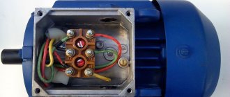
The terminal block contains the following inputs and outputs:
Designed for connection to a three-phase network. Before the soft starter, fuses must be included in the circuit. This is necessary to reduce the likelihood of thyristor breakdown during short circuits and the occurrence of transient processes. The Danffos company recommends using Ferraz and Bussman brands. Optionally, a circuit breaker and an overload controller can be connected.
The stator windings of the electric motor are connected to these terminals.
Inputs for line contactor.
Terminals for temperature sensor of electric motor windings. This soft starter model requires the use of thermistors. Engine shutdown temperature – 2.8 kOhm. If there is no sensor, the inputs are short-circuited with a jumper.
Control circuit inputs 24 V AC/DC; 110-240 AC and B 380 – 440 AC.
Direct launch
In a direct start electrical circuit, the machine is directly connected to the mains supply voltage.
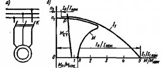
The diagram above shows the inrush current characteristic for direct starting. With this connection, the temperature increase in the windings of the machine is minimal.
The connection is made using a contactor (starter). The circuit uses an overload relay to protect the electric motor. However, this method is applicable when there are no current restrictions.
During the start of the machine, the starting torque is limited in order to smooth out a sharp jerk, as a result of which the mechanical parts of the drive and connected mechanisms may fail.
For this reason, manufacturers of large electric motors prohibit direct starting.
Carrying with BPP with rotation speed regulator
We suggest that you familiarize yourself with another option for a homemade carrier with a BPP and a rotation speed controller. The diagram presented below allows the power tool to run smoothly and reach the rated speed. The acceleration time to the declared speed depends directly on the capacity of the capacitor C3 used. To adjust the rotation speed, a variable resistor R2 of group A is used.
Scheme of a soft start unit with a speed controller
It is possible to install a soft release unit directly into the handle of the power tool, but this is a more complex upgrade and, as already mentioned, it may void the right to warranty repairs. The best option to assemble a soft start unit with a speed controller is to use a junction box. This circuit uses a TS122-25-5 triac, but you can install almost any device with a voltage of at least class four and a current of at least 1.5–2 nominal values.
Carrying with soft start unit and speed controller
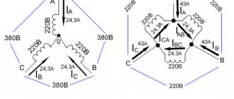
Star-delta connection
One of the main ways to start a machine is with a star-delta circuit. Such a start is possible for engines in which all the beginnings and ends of the windings are removed.
The start control according to this scheme consists of three contactors, an overload relay and a time relay that controls the contactors.
Initially, switching with the network occurs according to the “star” scheme. Contactors K1 and K3 are closed. Then, after a certain time, the windings switch automatically to the delta circuit. Contacts K3 open, and contacts K2, on the contrary, close. The time relay in the electrical circuit serves to control their switching. It sets the engine acceleration time. At the same time, starting currents are significantly reduced.
This method is effective, but it is not always used.
Control circuit connections
Starting and stopping the electric motor is realized by two- or three-wire circuits.
The drive starts by pressing a button. The electric machine is stopped by pressing again.
When choosing a three-wire circuit, smooth starting and braking of the engine is carried out by pressing the “start” and “stop” buttons.
The soft starter of this model allows you to adjust the starting voltage in the range from 30% to 75% of the nominal value of the electrical network. The default is 50%. The duration of voltage rise and fall is adjustable in the range from 2 to 20 seconds. This value determines the acceleration and stopping time of the electric machine.
All electrical connections are made with cables with copper conductors, grades and cross-sections recommended by the manufacturers. Drive settings and soft starter programming are carried out in accordance with the algorithm specified by the manufacturer. Before a test run, to check the operability of the drive, it is necessary to check the connection diagram and the correctness of the settings.
Alexander Sitnikov (Kirov region)
The circuit discussed in the article allows for shock-free starting and braking of the electric motor, increasing the service life of the equipment and reducing the load on the electrical network. A soft start is achieved by regulating the voltage on the motor windings with power thyristors.
Soft start devices (SPDs) are widely used in various electric drives. The block diagram of the developed soft starter is shown in Figure 1, and the operation diagram of the soft starter is shown in Figure 2. The basis of the soft starter is three pairs of back-to-back thyristors VS1 - VS6, connected to the break of each phase. Soft start is carried out due to gradual
Read also: Marking bolts and nuts by size
increasing the mains voltage applied to the motor windings from a certain initial value Un to the nominal Unom. This is achieved by gradually increasing the conduction angle of thyristors VS1 - VS6 from the minimum value to the maximum during the time Tstart, called the start time.
Typically, the value of Unat is 30...60% of Unom, so the starting torque of the electric motor is significantly less than if the electric motor is connected to full mains voltage. In this case, the drive belts are gradually tensioned and the gear wheels of the gearbox are smoothly engaged. This has a beneficial effect on reducing the dynamic loads of the electric drive and, as a result, helps to extend the service life of the mechanisms and increase the interval between repairs.
The use of a soft starter also makes it possible to reduce the load on the electrical network, since in this case the starting current of the electric motor is 2–4 rated motor current, and not 5–7 rated current, as with direct starting. This is important when powering electrical installations from energy sources of limited power, for example, diesel generator sets, uninterruptible power supplies and low-power transformer substations
(especially in rural areas). After the start-up is completed, the thyristors are bypassed by a bypass (bypass contactor) K, due to which during the time Trab the thyristors do not dissipate power, which means energy is saved.
When the engine is braking, the processes occur in the reverse order: after the contactor K is turned off, the conduction angle of the thyristors is maximum, the voltage on the motor windings is equal to the mains voltage minus the voltage drop across the thyristors. Then the conduction angle of the thyristors during the time Ttorm decreases to the minimum value, which corresponds to the cut-off voltage Uots, after which the conduction angle of the thyristors becomes zero and voltage is not applied to the windings. Figure 3 shows current diagrams of one of the motor phases with a gradual increase in the conduction angle of the thyristors.
Figure 4 shows fragments of the electrical circuit diagram of the soft starter. The full diagram is available on the magazine's website. For its operation, a voltage of three phases A, B, C of a standard 380 V network with a frequency of 50 Hz is required. The windings of the electric motor can be connected either by a star or a delta.
Inexpensive devices of type 40TPS12 in TO-247 housing with direct current Ipr = 35 A are used as power thyristors VS1 - VS6. The permissible current through the phase is Iadd = 2Ipr = 70 A. We will assume that the maximum starting current is 4Ir, which means that Inom (due to connecting a higher power motor or too short start time), the starting process will be stopped, since the QF1 circuit breaker with a specially selected characteristic will operate.
Damping RC chains R48, C20, C21, R50, C22, C23, R52, C24, C25 are connected in parallel to the thyristors, preventing false switching on of the thyristors, as well as varistors R49, R51 and R53, absorbing overvoltage pulses over 700 V. Bypass relays K1, K2, K3 type TR91-12VDC-SC-C with a rated current of 40 A shunt the power thyristors after the start is completed.
The control system is powered from a transformer power supply powered from the phase-to-phase voltage Uav. The power supply includes step-down transformers TV1, TV2, diode bridge VD1, current-limiting resistor R1, smoothing capacitors C1, C3, C5, noise suppression capacitors C2, C4, C6 and linear stabilizers DA1 and DA2, providing voltages of 12 and 5 V, respectively.
The control system is built using a DD1 microcontroller type PIC16F873. The microcontroller issues control pulses for thyristors VS1 – VS6 by “igniting” optosimistors ORT5-ORT10 (MOC3052). To limit the current in the control circuits of thyristors VS1 - VS6, resistors R36 - R47 are used. Control pulses are applied simultaneously to two thyristors with a delay relative to the beginning of the phase-to-phase voltage half-wave. Synchronization circuits with mains voltage consist of three similar units, consisting of charging resistors R13, R14, R18, R19, R23, R24, diodes VD3 - VD8, transistors VT1 - VT3, storage capacitors C17 - C19 and optocouplers OPT2 - OPT4. From output 4 of optocouplers OPT2, OPT3, OPT4, pulses with a duration of approximately 100 μs are received at the inputs of the microcontroller RC2, RC1, RC0, corresponding to the beginning of the negative half-wave of phase voltages Uab, Ubc, Uca.
The operation diagrams of the synchronization unit are shown in Figure 5. If we take the top graph as the mains voltage Uav, then the middle graph will correspond to the voltage on capacitor C17, and the bottom graph will correspond to the current through the photodiode of the ORT2 optocoupler. The microcontroller registers the clock pulses arriving at its inputs, determines the presence, the order of alternation, the absence of “sticking” of phases, and also calculates the delay time of the thyristor control pulses. The inputs of the synchronization circuits are protected from overvoltage by varistors R17, R22 and R27.
Using potentiometers R2, R3, R4, parameters corresponding to the soft starter operation diagram shown in Figure 2 are set; respectively, R2 – Tstart, R3 – Tbrake, R4 – Unstart Uots. The setpoint voltages from the motors R2, R3, R4 are supplied to the inputs RA2, RA1, RA0 of the DD1 microcircuit and converted using an ADC. The starting and braking times are adjustable from 3 to 15 s, and the initial voltage is adjustable from zero to a voltage corresponding to the thyristor conduction angle of 60 electrical degrees. Capacitors C8 - C10 are noise suppressing.
Read also: Soft start circuit for angle grinders
The “START” command is issued by closing contacts 1 and 2 of the XS2 connector, and a log appears at output 4 of the optocoupler OPT1. 1; capacitors C14 and C15 suppress oscillations arising due to “bouncing” of contacts. The open position of contacts 1 and 2 of the XS2 connector corresponds to the “STOP” command. Switching the launch control circuit can be realized with a latching button, toggle switch or relay contacts.
Power thyristors are protected from overheating by a B1009N thermostat with normally closed contacts located on the heat sink. When the temperature reaches 80°C, the thermostat contacts open, and a log level is sent to the RC3 input of the microcontroller. 1, indicating overheating.
LEDs HL1, HL2, HL3 serve as indicators of the following states:
- HL1 (green) “Ready” – no emergency conditions, ready to launch;
- HL2 (green) “Operation” – a blinking LED means that the soft starter is starting or braking the engine, constant light means it is working on bypass;
- HL3 (red) “Alarm” – indicates overheating of the heat sink, absence or “sticking” of phase voltages.
The bypass relays K1, K2, K3 are turned on by supplying a log to the microcontroller. 1 to the base of transistor VT4.
Programming of the microcontroller is in-circuit, for which connector XS3, diode VD2 and microswitch J1 are used. Elements ZQ1, C11, C12 form the clock generator start circuit, R5 and C7 are the power reset circuit, C13 filters noise along the microcontroller power buses.
Figure 6 shows a simplified algorithm for the operation of the soft starter. After initializing the microcontroller, the Error_Test subroutine is called, which determines the presence of emergency situations: overheating of the heat sink, inability to synchronize with the mains voltage due to phase loss, incorrect connection to the network or strong interference. If the emergency situation is not recorded, then the Error variable is assigned the value “0”, after returning from the subroutine the “Ready” LED lights up, and the circuit goes into standby mode for the “START” command. After registering the “START” command, the microcontroller performs an analogue-to-digital conversion of the setting voltages on the potentiometers and calculates the Tstart and Ustart parameters, after which it issues control pulses for the power thyristors. At the end of the start-up, the bypass is turned on. When the engine is braking, control processes are performed in the reverse order.
Practice has shown that we increasingly think about soft start devices only when we see a failed drive mechanism gearbox, when we have to change prematurely worn out and no longer useful drive belts, when we fix ruptured pipes, when there is a drop in supply voltage when turning on one or another. another unit knocks out all the protections and infuriates not only you, but also your neighbors.
The list of such unpleasant moments can be continued as long as desired, but the above facts should be enough to make you think: for what reason is all this happening?
A timely purchased and connected softstarter will allow you to avoid unnecessary costs and sometimes unnecessary headaches.
A soft start device is a mechanical, electrical or electromechanical equipment necessary for smooth start/stop of electric motors with a small starting moment of the working machine.
Start via autotransformer
This method is used by using an autotransformer in the electrical circuit, which is connected in series to the machine. It serves to ensure that startup occurs at a voltage reduced by 50 - 80% of the rated voltage. As a result, the starting current and starting torque will decrease. The time interval for switching from low to full voltage is adjusted.
However, there is a drawback here. During operation, the machine switches to mains voltage, which leads to a sharp jump in current.
A few words in conclusion
As you can see, the soft start unit is very important for a power tool, and it is quite easy to make. It allows you to significantly extend the life of drills, grinders and similar equipment, make working with them easier and protect you from injuries. The review presents the simplest and most affordable softstarter circuits that you can make yourself and quickly. If you have other effective schemes, then share them with us and our readers.
vote
Article rating
Soft starters
Under conditions of a smooth start of an asynchronous machine using thyristors in the electrical circuit of the power unit, a non-sinusoidal current is supplied. Acceleration and braking occur in a short period of time. Many people assemble a soft starter with their own hands. This greatly reduces its price.
In this circuit, the thyristors are connected in parallel in a circuit based on the counter principle. A control voltage is supplied to the common electrode. Such a device is usually called a triac. In the case of a three-phase system, it is present in each wire.
In order to remove the heat generated when semiconductors are heated, radiators are used. The dimensions, weight and price of devices increase.
There is another option to solve the heating problem. A shunt contact is connected to the circuit. After the start, the contacts close. In this case, a parallel circuit appears, the resistance of which is less than the resistance of semiconductors. And current, as you know, chooses the path of least resistance. While this process is happening, the triacs are cooling down. An example of such a connection is shown in the figure below.
Materials and tools
First you should prepare everything you need. To upgrade an electrical extension cord, you will need the extension cord itself, and in addition to it:
- outdoor socket;
- heat shrink tube or insulating tape;
- a piece of plywood or board;
- piece of wire 3*2.5;
- soldering iron and solder;
- knife;
- electronic soft start unit KRRQD12A.
Types of soft start devices
They can be divided into four categories.
- Regulating starting torque. Their operating principle is such that they control one phase. But when controlling a soft start, the starting currents are not reduced. Therefore, their range of applications is limited.
- Regulating voltage with no feedback signal. They work according to a given program and are among the most common in use.
- Regulating voltage with feedback signal. Their operating principle is the ability to change the voltage and regulate the current within a given range.
- Regulating current with the presence of a feedback signal. They are the most modern of all devices of this type. Provide the greatest control accuracy.
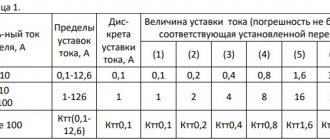
Selection of soft starter
The choice of a soft starter is made when designing or upgrading an electric drive. This takes into account equipment requirements, electrical network characteristics and other conditions. The main criteria are:
- Current, voltage and power of an electrical machine. It is necessary that the maximum possible current at start-up does not exceed the limit value of the soft starter current. The voltage and power of the device must match the characteristics of the engine.
- Number of starts and stops. This parameter is specified in the technical documentation of the soft starter; it must meet the operating conditions of the electric drive.
- The magnitude of the starting torque. The range of adjustable values must include the required permissible torque when starting the equipment.
- Electromagnetic compatibility. All electrical equipment of the drive must have the same EMC class.
- Allowable engine acceleration and deceleration times.
When choosing, the availability of dynamic braking functions, protection against abnormal operating conditions, and supported communication interfaces are also taken into account.
DIY creation
For budget models of angle grinders and other tools, you need to assemble your own soft starter. This is not difficult to do, because thanks to the Internet, you can find a huge number of schemes. The simplest and, at the same time, effective is a universal soft starter circuit based on a triac and a microcircuit.
When you turn on an angle grinder or other tool, damage to the windings and gearbox of the tool occurs due to a sudden start. Radio amateurs found a way out of this situation and proposed a simple soft start for a do-it-yourself power tool (diagram 1), assembled in a separate block (there is very little space in the case).
Scheme 1 – Scheme for soft start of a power tool.
The soft starter is implemented with your own hands on the basis of KR118PM1 (phase control) and a power unit using triacs. The main highlight of the device is its versatility, because it can be connected to any power tool. It is not only easy to install, but also does not require preliminary configuration. Basically, connecting the system to the instrument is not complicated and is installed in the break of the power cable.
Features of the soft starter module
When the grinder is turned on, voltage is applied to KR118PM1 and a smooth increase in voltage occurs at the control capacitor (C2) as the charge increases. The thyristors located in the microcircuit open gradually with a certain delay. The triac opens with a pause equal to the delay of the thyristors. For each subsequent voltage period, the delay gradually decreases and the tool starts smoothly.
The time to gain revolutions depends on capacity C2 (at 47 microns, the start-up time is 2 seconds). This delay is optimal, although it can be changed by increasing the capacitance C2. After turning off the angle grinder, capacitor C2 is discharged thanks to resistor R1 (discharge time is approximately 3 seconds at 68k).
This circuit for adjusting the speed of the electric motor can be upgraded by replacing R1 with a variable resistor. When the resistance value of the variable resistor changes, the power of the electric motor changes. Resistor R2 performs the function of controlling the amount of current that flows through the input of triac VS1 (it is advisable to provide cooling by a fan), which is the control one. Capacitors C1 and C3 serve to protect and control the microcircuit.
The triac is selected with the following characteristics: the maximum direct voltage is up to 400–500 V and the minimum current passing through the transitions must be at least 25 A. When manufacturing a soft starter according to this scheme, the power reserve can range from 2 kW to 5 kW.
Thus, to increase the service life of tools and motors, it is necessary to start them smoothly. This is due to the design feature of electric motors of asynchronous and commutator types. When starting up, there is a rapid current consumption, which causes wear and tear on the electrical and mechanical parts. Using a soft starter allows you to protect your power tool by following safety regulations. When upgrading a tool, it is possible to purchase ready-made models, as well as assemble a simple and reliable universal device, which is not only different, but even superior to some factory soft starters.
Modification for grinders interskol with a 15 A triac
Soft start for a device with 15 A triacs is considered universal and is often found in low-power types. The difference between the devices is their low conductivity. The circuit (device) for such a start involves the use of transceivers of a certain type, which operate at a frequency of forty Hz. Many species use comparators. Such parts are supplied with filters. The rated voltage of starters starts from 200 V.
Starters for angle grinders with a 20 A triac
Devices with 20 A triacs are suitable for professional grinders. Many types use special resistors. First of all, they can operate at high frequencies. The maximum temperature of the starters is fifty-five degrees. Most devices have a well-protected case. The classic scheme involves the use of 3 contactors with a capacity of thirty pF or more. Craftsmen believe that the devices stand out for their conductivity.
- The lowest frequency for starters is about thirty-five Hz. They can operate in a DC network. The model is connected via adapters. Such devices are perfect for two hundred W motors. Filters are very often installed with triodes. Their sensitivity indicator is 300 mV and no more.
- Quite often you can find special comparators with a protection system. If you look at foreign models, they have an integrated converter that comes with insulators. Current conductivity is produced at around five microns. With a resistance of forty ohms, the model can maintain high speeds for a long time.
Models for angle grinder 600 W
- For 600 W instruments, use starters with contact triacs; they have an overload of no more than ten A. Also remember that there are many devices with plates. They are good for their security and will not be afraid of rising temperatures. The minimum frequency for 600 W devices is 30 Hz. In this case, the resistance will depend on the supplied triode. If it is used linear type, then the above parameter will not exceed 50 Ohms.
- If we talk about duplex triodes, then the resistance at high speeds can reach up to 80 Ohms. Very rarely, models may have stabilizers that operate from comparators. In most cases, they are attached directly to the modules. Some types are created with wired transistors. Their lowest frequency starts from five Hz. They are afraid of overload, but can maintain huge speeds at 220 volts.
Devices for grinders at 800 volts
800 W devices can operate with low frequency starters. Triacs are often used at fifteen A. If you look at the diagram of the models, you should notice that they use special transistors whose current carrying capacity starts from 45 microns. Capacitors are used with or without filters, and the capacitance of the parts is no more than three pF. It is also worth knowing that starters may differ in sensitivity. Lever with speed control and soft start. Angle grinder Makita GA5030. The Makita grinder with speed control is one of the most popular models. The range of rotation adjustment will depend entirely on the maximum diameter of the nozzle.
Remember that there is a high probability of breakdown of the electric motor and breakdown of the device after not a soft start, but a sharp, jerky start. Therefore, it is better to make a limiter, fulfilling the restrictions can directly protect the engine. The device should also have a commutator motor, not an asynchronous one, so that everything can be safely turned off. The block is needed to supply power to the switching relays.
Well, and most importantly, the start button must be installed correctly, and even better, look at the electrical diagram before creating your own device. It is better to carry out repairs of models kr1182pm1, xs, 12, d3 carefully, because such devices are expensive.