Electrical machines › DC electric machines
A characteristic feature of collector machines is the presence of a collector - a mechanical converter of alternating current into direct current and vice versa. The need for such a converter is explained by the fact that alternating current must flow in the armature winding of the commutator machine, since only in this case a continuous process of electromechanical energy conversion occurs in the machine.
DC commutator machines include a DC motor DPT and a DC generator GPT which have the same design and can replace each other, that is, a DPT can work like a GPT and vice versa. Let us analyze the design of commutator machines using the example of a DC motor.
The DC commutator machine consists of:
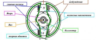
- Anchors (moving part) which consists of a shaft, armature winding, commutator, two bearings and a core. The core is a cylinder made of stamped sheets of electrical steel 0.5 mm thick coated with electrical insulating varnish. This prefabricated structure serves to reduce eddy currents. There are grooves in the core into which the groove sides of the armature winding are inserted.
- Stator (4) (fixed part) - frame, main poles with pole coils (2,3).
The stator can be structurally of two types:
- prefabricated - consists of a solid drawn pipe and poles attached to it inside. The pole core is made in the form of a steel bar or from laminated plates 0.5 - 1 mm. The pole winding is wound around the core. The pole windings are connected to each other in series and form an excitation winding which, when connected to a direct current source, creates a magnetic field in the magnetic system of the motor.
- solid laminated - used in machines with a power of 600 W or more. It consists of a package of electrical steel plates of complex configuration with a thickness of 0.35 - 0.5 mm.
Brush-commutator transition device.
The most complex and unreliable part of the commutator machine is the brush-commutator junction , which consists of brushes (which are attached to brush holders) and a commutator, which consists of a set of commutator plates of a trapezoidal cross-section, separated by micanite spacers. Plates made of copper and micanite are held in a compressed state by the dovetail-shaped lower part by means of steel conical rings 1 (Fig. 13.2). The part of the commutator plates 6 protruding upward, called the “cockerel,” serves to connect the armature winding sections to the commutator plates. The collector plates are isolated from the conical rings with micanite cuffs 3, and from the bushing 5 with a micanite insulating cylinder 4.
The surface of the copper plates of the collector is gradually abraded by brushes during operation of the machine. To prevent the micanite spacers from protruding above the working surface of the copper plates, which could lead to disruption of the electrical contact of the commutator with the brushes, it is necessary to periodically “condition” the commutator. This operation consists of milling grooves (tracks) between the working surfaces of the collector plates to a depth of 1.5 mm (Fig. 13.4).
Design of a commutator DC motor
Stator
- stationary part of the engine.
Inductor
(excitation system) - part of a DC commutator machine or synchronous machine that creates a magnetic flux to generate torque.
The inductor necessarily includes either permanent magnets
or
an excitation winding
. The inductor can be part of both the rotor and the stator. In the engine shown in Fig. 1, the excitation system consists of two permanent magnets and is part of the stator.
Anchor
- part of a DC commutator machine or synchronous machine in which an electromotive force is induced and a load current flows [2]. Both the rotor and the stator can act as an armature. In the engine shown in Fig. 1, the rotor is an armature.
Advantages and disadvantages of DC collector machines.
DC electric machines are used both as generators and motors. The most widely used are DC motors, the power range of which is quite wide: from fractions of a watt (for driving automation devices) to several thousand kilowatts (for driving rolling mills, mine hoists and other large mechanisms).
DC motors are widely used to drive hoisting devices, such as crane motors and vehicle drives, and also as traction motors.
The main advantages of DC motors compared to brushless AC motors are good starting and control properties, the ability to obtain a rotation speed of more than 3000 rpm, and the disadvantages are relatively high cost, some complexity in manufacturing, and reduced reliability. These disadvantages of DC machines are due to collector unit in them , which is also a source of radio interference and a fire hazard. But, despite the noted disadvantages, DC motors are still indispensable in some cases, since they have a large overload capacity and good starting and control properties.
Working principle of DC motor
DC brushed motors
A unique property of collector machines is the reversibility of these devices. What do these mean?
- It's simple! These units are capable of operating both in motor mode and in DC generator mode, with appropriate connection of the motor stator and rotor.
- When a DC machine is connected to an energy source, current begins to flow in the rotor and stator windings of the unit. In both places, electromagnetic fields are instantly formed - armatures and excitations. The interaction of these fields creates a certain electromagnetic torque (M) on the rotor.
- This torque is rotating and does not have a braking effect, as in a current generator.
- Under the influence of the moment M, the anchor begins to move. In this case, electrical energy is consumed from the supply network.
- When the rotor starts to move, an EMF begins to be induced in its winding, similar to what we described in the previous chapter.
DC commutator motors - the right-hand rule will help determine the direction of the magnetic field of the armature winding
- The direction of the EMF is easily determined by the left-hand rule, a detailed description of which is presented in the figure above.
- It is interesting that this EMF will be directed in the opposite direction to the current feeding the rotor, therefore this force is called back-EMF, that is, it brakes the armature.
- Without going into formulas and calculations, we can simply say that when the electromagnetic torque increases, that is, when the load on the motor shaft increases, the power in the armature winding (at the motor input) increases.
- We know that the voltage supplied to the motor remains constant, which means that due to an increase in load, the current supplying the rotor increases.
- In other words, the armature rotation frequency will be directly proportional to the voltage and inversely proportional to the exciting flux. Increasing current increases torque at a constant load torque
- To put it even more simply, clamp the motor shaft with something. At the same time, its rotation will slow down, and the current strength will increase. Increase the current without putting a load on the shaft, it will spin up more, it’s simple.
Interesting to know! If the load on the shaft is so strong that it causes it to rotate in the opposite direction during operation, the engine will switch to generator mode.
Types of DC motors
DC brushed motor for compact devices
All DC motors can be divided according to their power and purpose:
- The smallest specimens have a power of several watts.
- They are usually installed in small devices and children's toys. Their operating voltage varies between 3-9 Volts, which can be provided by ordinary batteries.
- The structure of the main working parts of such motors is as follows: a three-pole rotor, a commutator with the appropriate number of plates, a two-pole stator, the role of which is played by permanent magnets.
- DC commutator motors of medium power, which produce tens of watts.
- Their structure is slightly different: a multi-pole rotor and commutator, a brush apparatus of two or four brushes, a four-pole stator with permanent magnets.
DC motors, commutator
- Powerful units that produce and consume hundreds and thousands of watts of energy have almost the same structure, but instead of low-power permanent magnets they use electric ones.
Methods of exciting DC motors
Methods for connecting DC motors
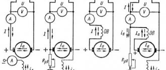
There are four ways to excite a DC motor.
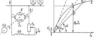
Independent excitation
It is not difficult to guess that with such a scheme, the motor armature is powered from the main DC source - from the network, generator or rectifier, and the field winding is connected to an additional source.
- The excitation winding has an adjustable rheostat, which allows you to control the operating modes of the engine.
- A starting rheostat is connected to the rotor winding circuit. Its purpose is to limit the current when starting the engine.
- A feature of this scheme is that the exciting currents do not depend on the load currents, which means that the magnetic flux of the motor will practically not depend on the load. That is, the dependence of rotation speed and torque will be linear.
- A huge disadvantage of such an engine is that if it is turned on without load, the rotation speed will become very high, which can even lead to its failure. The current in the armature winding increases greatly, which can cause a circular fire.
- Automation protects against engine operation in this mode by cutting off the power supply.
Interesting to know! Purely theoretically, operation in this mode cannot force the rotor rotation speed to constantly increase. It will stop increasing when the back EMF reaches the supply voltage.
- If the excitation circuit breaks during operation of such a motor, provided that the load on the shaft is close to the nominal load, the motor will stop, since the electromagnetic torque will become less than the load on the shaft. In this case, the current in the armature winding will also increase sharply, which will lead to its overheating and other unpleasant consequences.
Parallel excitation
Parallel excitation circuit
In this circuit, both windings are powered from the same source. The circuit also includes two rheostats - adjusting and starting.
- Despite being connected to the same network, the power supply essentially remains independent, which means that the field winding current will also not depend on the armature winding current.
- An engine with this connection has the same characteristics as an independent one.
- However, there is a difference - such a motor will only work if the voltage of the power source remains unchanged.
Sequential excitation
Series drive circuit
The field winding is connected in series with the armature.
- To limit the starting current, a starting rheostat can be included in the circuit, and a control rheostat can also be included.
- With this connection, the winding currents are already dependent on each other. When the rheostat is turned on, they will be equal, which means the magnetic flux will depend on the load.
- The magnetic system of the machine will not be saturated until the armature winding current is 80-90% of the rated current. The magnetic flux will change in direct proportion to the current, which is why the speed characteristic of the unit will be soft.
- As the current increases, the rotation speed of such a motor decreases. This occurs due to an increase in the voltage drop in the resistance of the armature winding circuit, as well as due to the fact that the magnetic flux increases.
- When the current becomes greater than the rated one, the dependences of rotation speed and torque become linear, because the magnetic circuit becomes saturated, that is, when the current changes, the magnetic flux will no longer change.
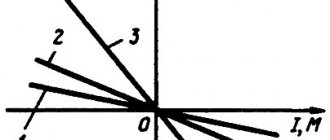
Mechanical characteristics of the engine
- The mechanical characteristic of such an engine has a hyperbolic shape. At low loads, the magnetic flux will greatly decrease and the rotation speed will increase, which can also lead to the engine running out of gear.
- This circumstance limits the use of these units in systems that require operation at idle or at low loads.
Interesting to know! The minimum permissible load for series-wound motors is 20-25% of the rated value. To prevent the engine from starting without load, it is connected to the drive through a rigid blind coupling or gear drive. Belt drives and friction clutches cannot be used, as a breakage may occur, and you already know the consequences.
Interestingly, despite this drawback, these engines are very common, especially where there is a change in load and difficult starting conditions, for example, in electric locomotives, electric cars, diesel locomotives, etc.
And this is very simple to explain - with a soft characteristic, an increase in load does not lead to a strong increase in current and energy consumption, which means that these units cope better with overloads. Also, do not forget about the high starting torque, which the previously considered engine options lack.