When connecting a hob, you may encounter problems that make not only the average user, but also an experienced electrician think:
- which cable to choose for installing electrical wiring from the panel to the hob
- how to connect the panel in the electrical panel
- how to connect 4 wires coming out of the stove and 3 wires of the electrical wiring power cable
- how to connect correctly and not mix up the cable cores on the terminal block
We will consider all these points in detail below. But first, let's decide on possible additional purchases. To connect the hob you will need the following materials:
- cable VVGng-Ls or NYM
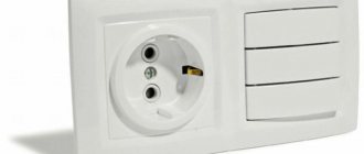
- special socket + plug for stoves with current 32A-40A (you can order a similar connector here)
- PVS wire, if no wires are included with the panel
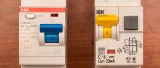
- differential machine
- NShV tips
- terminal block or GML sleeves
Origins of the problem
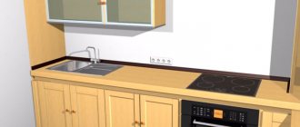
Often in the kitchen of an apartment or private house there is only one electrical outlet at the equipment connection point. This is how the living space was designed, especially for old houses.
At the same time, we are faced with the task of ensuring the connection of two independent loads simultaneously, each of which has its own electrical input.
This situation becomes critical when the electrical equipment:
- has high power, which does not allow solving the problem through a multi-socket extension cord or tee;
- due to its purpose, it was not initially designed for frequent connections and disconnections.
An additional complicating factor is that the electrical appliances located at a given load point, in our case the oven and hob, must function simultaneously, and the problem cannot be solved by alternatively connecting one of the devices to another point.
Connecting the hob
There are three main connection schemes. Let's look at them in detail.
When connecting cables to the socket and terminals of the electric stove, follow the color coding - this will allow you to avoid mistakes.
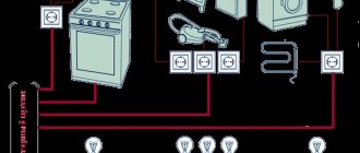
Three-phase 380V circuit (common in private homes and businesses)
Phases A, B, C – are connected to terminals L1-3 of the hob. In this case, it is necessary to remove the jumpers installed at the factory between terminals L1-3. Zero N is connected to terminals N1-2. Protective conductor PE – to the PE terminal.
Connecting the oven is much easier. Most often, such devices are already supplied with an electrical cord with a plug for connection, so the Euro plug is simply inserted into a Euro socket. To connect to machines or terminals, it is best to use a separate cable, since if you cut off the plug on the cable from the kit, this can significantly affect the warranty for this device.
The oven connection diagram is always single-phase:
- Phase L is connected to terminal L of the oven;
- Zero N is connected to terminal N;
- Protective conductor PE – to the PE terminal.
Single-phase circuit 220V
The most common option in apartments. As follows:
- Phase L is simultaneously connected to terminals L1-3. To do this, we install two copper jumpers between them (they are already included with the stove).
- Zero N is connected to terminals N1-2.
- Protective conductor PE – to the PE terminal.
You can access the terminals of the electrical surface through its back cover - it is unscrewed and removed.
Two-phase circuit 380V
It may also be that in a country house or apartment there are not three phases, but two: A and C are present, but B is missing. In this situation, the hob is connected to a 380V network using a two-phase circuit:
- A jumper is placed on L1-2 and phase A is connected.
- At L3 – phase C.
- The rest is similar to the previous options.
If for some reason you do not have jumpers, you can make them yourself from a wire whose cross-section is no less than that of the supply (i.e. 6 mm²).
For flexible wire, use insulated ring or fork lugs to ensure better contact with the terminal. They are pressed onto the core using special press jaws.
Justification for separate connection
The PUE states that to power household loads whose power exceeds 3.5 kW, a dedicated cable with a separate circuit breaker must be used. This means that for power supply a radial circuit must be implemented.
In our case, the hob often has a power that is higher than one kilowatt. Despite the fact that the oven is a less powerful device, there are models that consume one and a half kilowatts or more.
Therefore, these two devices can be considered as a single whole not only from the point of view of functional purpose: cooking, but also load.
Which wire should I use for the air conditioner?
Everything here is generally very simple. Considering that air conditioners rarely have a power of more than 3 kW (except for industrial ones), they can be freely connected to an outlet. However, as in the case of an oven, the air conditioner must be “placed” on a separate outlet, to which nothing else will be connected.
Accordingly, to connect an air conditioner with a power of up to 3 kW, for example, Electrolux EACS-09HG2/N3, a three-core copper wire with a cross-section of 1.5 mm2 is sufficient.
Interesting things from the world of electrical wiring:
- Wiring in a wooden house: how to avoid fire
- How to be sure to choose a good cable for wiring?
Preliminary remarks
When connecting the oven and hob, a number of requirements must be met regarding wiring and circuit breaker:
These include:
- the wire is known to be in good condition;
- withstands prolonged maximum load;
- contains the required number of working conductors, neutral and grounding;
- complies with all safety standards.
When choosing a machine, it makes sense to be guided by the values of 25 A with a total load power of up to 5 kW and 32 A with a higher power (see table below).
Table. Limit parameters of 220-volt single-phase wiring for cables with a core cross-section of 4 mm2.
| Exposed wiring or box | Closed wiring (in a groove) | |||
| Core material | Copper | Aluminum | Copper | Aluminum |
| Current, A | 41 | 32 | 27 | 21 |
| Power. kW | 9 | 7 | 5,9 | 4,6 |
Connection with sleeves
Now you need to connect the wiring in the socket box with the cable going to the panel. Select GML sleeves that correspond to the cross-section of the cores.
If the sections of the cores are different, for example, 6mm2 comes out of the wall, and 4mm2 goes to the panel, then on one side (smaller) the sleeve is sealed with an additional wire.
After which the ends are pressed in with press pliers and insulated with electrical tape or thermal tube.
Now all this can be neatly hidden in the socket box.
Selection of household appliances based on the possibility of existing wiring
Let's go a little deeper into the topic so that everything is clear.
If you are just planning to buy an oven and hob, then it is important to understand whether the existing wiring will withstand the total power of both devices, and not a short-term, but a long-term load.
To do this, you need to find out what cross-section of wires the wires have and based on this, make calculations or use ready-made tables.
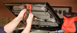
To measure the cross-section of the wire, use a caliper. An ordinary ruler will not work, as the measurements will have a large error.
Do the following:
- Disconnect the cable.
- Strip the insulation of one core to at least 1 cm.
- Take measurements using a compass.
Next, use the formula from the school course: S=π×d²÷4.
Where:
- S is the required cross-sectional area.
- D – measured diameter.
- Π = 3.14.
For example, measurements showed a core diameter of 2.4 mm. We carry out the calculation: 3.14x2.42÷4=4.52mm2. The recommended value is from 4 to 6 square millimeters.
In new houses built after 2001, the conductors are usually copper, in old ones they are mainly aluminum.
Further, using the table below, you can find out how much power this cable can withstand.
Information about wire and cable brands PVS and KG
The abbreviation PVS stands for vinyl connecting wire. Used to connect electrical devices and instruments to the power supply network. It is a product with conductive copper conductors (from 2 to 5), protected by insulation (each conductor) and enclosed in a common white insulating sheath. The symbol of a wire, in addition to the abbreviation PVS, includes the number of cores and the diameter of each core, for example, the designation PVS 3x4 is deciphered as follows: a vinyl connecting wire with three conductive cores with a diameter of 4 mm. PVA can withstand a voltage of 450 V. The insulation material does not support combustion, which classifies the wire as a standard product class for fire resistance. Has high strength and bending resistance. The wire can be used in damp and unheated areas. Depending on operating conditions, it lasts from 6 to 10 years. The low price makes it popular when connecting electric stoves of different power.
cable KG
The abbreviation KG stands for flexible cable. The role of the shell in it is played by special rubber. Inside the cable there are also tinned copper conductors in a rubber sheath, and between them there is a protective film, the purpose of which is to prevent sticking as a result of heating during operation. Produced by manufacturers with a number of cores from 1 to 5. The cross-section of the core determines the power that the cable can withstand. The cable can be used within a fairly wide range - from minus 40 to 50 0C in rooms with high humidity at an electrical network voltage of up to 660 V.
The symbol consists of the abbreviation KG, the number of phase and grounding conductors, indicating their cross-section. For example, the designation KG 3x5+1x4 is deciphered as follows: 3 phase conductors with a cross-section of 5.0 mm2 and 1 grounding conductor with a cross-section of 4 mm2.
Regardless of which brand is selected to connect an electric kitchen device, the wire or cable must be purchased with a reserve length so that the product can be moved. PVA and KG are easy to install due to their increased flexibility and are simply connected to the slab. When connecting to the contacts of the product, the ends of the wire or cable must be cleaned from oxidation, tinned, and then they can be secured as follows:
- giving the required shape and clamping with washers;
- compression in special sleeves;
- using TML type tips.
About the demand coefficient
The demand coefficient is calculated using the formula Ks = Рр/Рн, where:
- Рр – design power.
- Рн is the total power of electrical consumers, in our case the oven and hob.
In simple words, if the demand coefficient is 1, this means that it is possible to simultaneously use all electrical appliances on one network at maximum capacity. But in practice this rarely happens.
For example, 0.7 indicates that electrical appliances are used separately or simultaneously, but not at maximum loads, provided that they are connected to one point.
Below is a table for calculating the power consumption of an apartment taking into account the demand coefficient.
What do we mean by this? And the fact is that if with a wire with a cross-section of 4 mm2 and a load it can withstand of 5.9 kW, you can purchase electrical appliances that in total consume more power.
For example, you liked certain oven and hob models that consume a total of 8 kW at maximum load. But you do not plan to use these electrical appliances in this mode.
We multiply 8 kW by the demand factor of 0.7 (you can take less, but this figure is the most optimal), we get 5.6 kW, which suits you quite well.
What connectors to use for the oven
To save as much space as possible and not fill the box with wires, it should be at least 10x10x5 cm. There is no need to save space because the unit will be covered by kitchen furniture.
To prevent the wires from being pulled, it is better to make loops at the ends of the wires (picture on the right) when connecting. As you can see in the above pictures, a special terminal block with screw terminals is used for three-phase conductors, neutral conductor and protective conductor. Its advantage is that after opening the lid you can see everything connected to it.
The rated current, that is, the maximum current that can flow through each terminal for a long time, for a single-phase network should be at least 32 A.
The use of spring terminal blocks for three-phase systems is not a problem and can be used quite well. They have a rated current of 24 A. But in a single-phase network, this is usually not enough to reliably connect an induction hob - it is better to use screw terminals.
Connection options
You can connect electrical appliances to the network using detachable and permanent methods.
Options for connecting the panel and cabinet to the electrical network
A detachable connection is based on the use of a plug and socket, which are pre-mounted on the cable: the connected equipment and wiring, respectively. It's convenient and practical.
Permanent connections are made through the terminal block. The advantages of this connection method are a strong and reliable connection of contact pairs and lower cost.
How to connect an induction hob yourself
If there is already a sufficiently powerful initially or upgraded electrical network in the house, this greatly simplifies the matter. But you still can’t just plug a plug into a regular socket and leave it at that. You need to make sure that the network parameters in the apartment are not lower than required according to the instructions. And ideally, even better protection should be provided.
If the technical data sheet indicates that the protection should be designed for 30 A, then it is advisable to use network protective elements of 25 A. Having dealt with this point, you can also deal with the cable. When a standard connection to the output cable is provided, the following conductors can be used:
- black or brown color (phase);
- yellow-green tone (protection);
- blue and gray colors (neutral).
Sometimes the wire cross-section is not suitable. Power cords with a cross section of 2.5 square meters. mm must be protected by switches with reduced current rating. The most commonly used elements are type B16. But this imposes very strict restrictions on the amount of current consumed. Otherwise, the switch may trip when more than two heating fields are in use.
Some induction devices are connected not using wires, but using terminals. In this case, the design has a special terminal, usually located at the bottom. But there are other situations - for example, when you need to connect an induction hob to a three-phase network designed for 380 V. In this case, instead of three phases, two are usually used. This is the approach most manufacturers take.
It is quite correct and quite simple to connect two heating fields to one phase, and two to the other. In this case, one phase has two average values, and the other has the weakest and strongest currents. In such a scheme there is no need to use gray L3 cables. In some cases, there is a need to interconnect terminals on the board.
This is a very simple task: you just need to use the included board. The wires are twisted with a screwdriver, and this is where the work ends. Here we need to return to connecting hobs using terminals and cover this topic in more detail. The cable ends in the installation box. If the cable is not included in the kit, you need to additionally buy a wire of the OMY model (aka ShVVP).
It is correct to connect the non-working phase to the oven. This will allow the phase to be loaded evenly. In some cases, separate 3x2.5 m cables are used, coming from distribution devices. Then you need to connect such cables to single-phase switches of the highest load. This solution allows, if the operation of one of the devices malfunctions, to use another without the slightest difficulty.
Connection via socket
In practice, the following main versions of sockets are used, which are shown schematically in the figure below:
- assembly of two single sockets with a separate cable for each of them;
- assembly of two single sockets with a common cable;
- monoblock socket with two seats for plugs.
Options for the end section of wiring for connecting the hob and cabinet, from top to bottom:
- with individual cable and circuit breaker for each socket;
- with the installation of a monoblock double socket and a common circuit breaker;
- using a daisy chain connection of two sockets and a common circuit breaker.
Taking into account the high power of electricity consumed, monoblock sockets with three or more seats are not used in this connection method.
The type of socket used is significantly limited if the panel and/or oven cable is reinforced with a plug. You cannot change it for another one, since in this case, at a minimum, the factory warranty will expire.
When connecting, it is advisable to use socket modules with different form factors, which are also available in a double monoblock version.
Dual power socket with different form factors and the option of lateral cable supply to it in a brick wall groove
Connection via junction box
Sleeving is inconvenient because, firstly, the connection is not dismountable, and secondly, crimping requires a special tool. Not everyone has a press, and you cannot crimp such connections with pliers.
In this case, the KlK-5S mounting box will come to the rescue. Apart from a screwdriver, you don’t need anything here, and the outgoing cable can be disconnected at any time.
True, its contacts can be quite delicate, so do not overdo it with the tightening force.
In addition, its overall dimensions, unlike powerful sockets, are small and the whole thing can be conveniently mounted behind kitchen cabinets.
The connection is made traditionally:
- zero via screw terminal N (blue wires)
- the ground is indicated by the “grounding” icon - yellow-green conductor
- There are three phase connectors on top. If you have 220V, remove the extra phases and isolate them.
Connection via terminal block
This connection is made in two cases:
- if the connecting cable of the hob or oven does not have a plug;
- if a terminal block is installed on the device itself as an element of connection to the network.
Figure 4 shows both of these cases in schematic form.
Options for connecting the cable to the panel and oven
In the latter case, to connect, connect two terminal blocks with a cable: the device itself and the linear one, and the cable itself is not included in the delivery package of the device and must be purchased separately.
This option is labor-intensive to implement, but does not limit the distance between the cabinet/hob and the power cable exit point, and also allows you to very accurately select the length of the connection cable and avoid the formation of loops.
Most often, the functions of a linear terminal block are performed by a so-called barrier block.
One of the barrier block options
This type of terminal block got its name due to the presence of a protrusion-barrier separating the fastening components of the input and output sides of the device.
The block can be installed openly on the wall or mounted inside a cutting box, for which it is provided with appropriate mounting holes for screws or screws.
Do-it-yourself calculation of cable cross-section by power
The correct choice of cable cross-section allows you to install the wiring so that all property and residents of the apartment are safe. In order to save money, many choose thinner wires for wiring and instead of a copper core, they choose an aluminum one.
This may lead to the following consequences:
- The passage of high power current through an incorrectly selected cable will cause it to heat up, which will destroy the insulation. The cable will burn out, leaving the circuit without power.
- Often sudden surges in electricity can heat up the metal so much that it leads to a fire due to thermal effects on surrounding objects, for example, wallpaper.
- As the temperature of the cable increases, the resistance in the circuit increases, which provokes a change in the current-voltage characteristics of the power sections. This often leads to equipment failure.
- Broken insulation leads to exposed wire, which is extremely dangerous upon contact. If the location of the defect is unknown, it is quite difficult to protect yourself.
- The problematic section of the wiring, which is built into the wall, is not easy to find. In some cases, a complete replacement of the wiring from the source to the problem area is required. In the end, all this can result in large costs - you will have to pay an electrician, buy a new cable and carry out work along the cable path.
To select a cable, you need to perform preliminary calculations:
- count how many electrical appliances are installed in each room;
- calculate the total load for each connection point to the power grid.
After selecting the conductor, the cross-section is calculated in accordance with the load on a separate room. Everything will depend on how the network will be organized, how it is planned to connect the points (series or parallel).
Important. Copper has a higher conductivity than aluminum, so wires made from these materials will not give the same result when calculating power.
To understand the process of calculating a cable cross-section depending on the current power, you need to understand the essence of the process of transmitting electricity. For clarity, imagine several thin water pipes that need to be placed in a circle parallel to each other.
The wider the circle, the more pipes will fit in a tight arrangement. The pressure of a large system will be greater than that of a small one. It's the same with electricity. Because current flows along the surface of the conductor, thicker cables can withstand greater loads.
Errors in cross-section calculations occur in the following cases:
- The vein is too wide. Wiring costs increase and cable resources are used irrationally.
- The channel width is less than required. The current density increases, heating the insulation and conductor, which leads to the formation of “weak” spots on the cable and leakage of electricity.
Power is calculated by multiplying the voltage in the conductor by the current. The household network is designed for 220 V, therefore, to determine the cable cross-section, you need to know the power and current in the circuit. After calculating the load and current using the PEU tables, the size of the wire is found.
It is easier to determine the cross-sectional area by the diameter of the core. Area is measured in square meters. mm, and the diameter is in mm. Using these indicators, you can find in the table the permissible power by size and type of wire. If there is no data on the diameter of the wiring, the area is calculated using the following formula:
S = 3.14 * D2 / 4 = 0.785D2, where: S – cable cross-sectional area; D – diameter value.
If the shape of the conductor core is rectangular or square, then the cross-section is calculated by multiplying the length by the width.
An accurate calculation of the cross-section is carried out taking into account the following indicators:
- type and type of insulation;
- configuration and length of sections;
- method of installation (external or hidden);
- maximum permissible overheating;
- room temperature;
- difference in power indicators of devices connected to the same outlet;
- level and percentage of humidity in the room.
After calculating the power, the current in a household network with a voltage of 220 V is calculated using the following formula:
I = (P1 + P2 + … + Pn) / U220, where: I – current strength; P1 ... Pn – power of each consumer in the list – from the first to the n-th; U220 is the network voltage, in our case it is 220 V.
Calculation formula for a three-phase network with a voltage of 380 V:
I = (P1 + P2 + .... + Pn) / v3 / U380, where: U380 is the voltage in the three-phase network equal to 380 V.
It is easy to independently calculate the cable cross-section yourself, without resorting to outside help. If the room has a distribution panel and there are no complex installation systems, then repairs can be done without the involvement of specialists. But if the humidity and temperature in the room are high, you will need the help of professionals.
Features of connecting the panel and cabinet to the barrier block
There are two things to consider during the connection process.
The first of them is that the connection of the panel and cabinet to the linear terminal block, regardless of the design of the connection block of the device itself, is always performed according to a star circuit, which is shown in schematic form on the left side of the figure.
Connection diagram of line terminal block, hob and cabinet
The use of a loop circuit on the right side of the figure is not recommended due to the fact that the fixing elements of the hob terminal block are not initially designed to connect two wires to it.
The second feature is that, given the large currents flowing through the socket, it is necessary to ensure low contact resistance in the area where the panel/oven cables connect to the terminal block.
To achieve this effect do:
- reinforcement of individual cable wires with lugs (an example of such a component is shown in the figure below);
- the use of a special crimping tool for their installation.
Fork-type tubular cable crimp lug
The correct connection is additionally checked by the color of the insulation of the individual cable cores, their purpose is additionally controlled by the accompanying documentation of the device.
Connection diagram to the machine.
CS-CS.Net: Laboratory of the Electroshaman
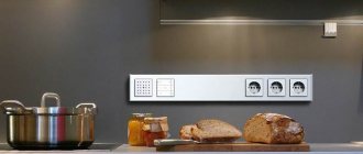
Small boxes ABB components for organizing the panel in the kitchen plinth
Attention! Some of the comments from this post were moved to an archived post because there were a lot of them and the page took a long time to load. If you didn’t find something, please go to this archived post! There were many interesting discussions there!
The post was inspired by several topics on MasterCity.ru and a bunch of angry debates, for which they could easily get themselves banned on the forum. Because I almost had to move to the mat. All these topics are united by one question: how to connect the cooker and oven in the kitchen ?
This post is intended ONLY for the case when you (or stupid craftsmen) have already laid the wiring and cannot be moved. In other cases, ALWAYS place a separate cable for the cooker and a separate cable for the oven.
“Yopt!”, an inexperienced reader will say, “What is there to write about?! I twisted the cable into the cooker, stuck the plug into the socket and forgot about it!” Well, as always, our theory and practice differ sharply. This feature is like this: first do it, and then fuck half the forum residents’ brains on how to get out of what was done incorrectly.
Situations often arise on forums when a person, thinking inertially due to the fact that he previously had one electric stove, lays one cable for a new kitchen during renovation. And then it turns out that the appliance being installed consists of a separate oven and a separate hob, which need to be powered somehow. And this is where the brain begins to INVENT. The very first solution that comes to mind is to cut the plug at the oven and attach its cable to the hob cable. This decision is completely wrong!
An example of a TERRIBLE connection of a cooker, oven and dishwasher to one cable (sent by izhplan)
Therefore, first we write it correctly. The following is correct. First, try to target certain models of cooker and oven in advance. You will still have to resolve this issue when ordering a kitchen. In general, the kitchen and electrics are sometimes indivisible things: before starting electrical work, you need to know where the built-in appliances will be (oven, dishwasher, microwave), how many there will be, what they are powered by. And only then design and lay the cables.
Secondly, study how these cooktop and oven models are connected. Typically there are the following options:
- Standard wire with plug. This is primarily typical for ovens with a power of up to 3.5..3.6 kW. They have a regular wire and a 16A plug. This plug should be plugged into a regular 16A outlet. Cutting off the plug usually results in complete loss of the warranty on the equipment. Conventional old-style electric stoves also have a wire and plug. Freestanding. The forks there are usually weak and barely hold on (remember those round black ones in the USSR?), and it is useful to replace them. Either on a solid cable (will be discussed below) or on an industrial connector =)
- A piece of cable. This is typical for some hobs. It seems that this is BOSCH - their cable is embedded directly into the panel, and it cannot be unscrewed or rearranged. You can either install an industrial connector on such a cable, or connect it directly to the cooker’s power cable via a terminal block (recommended). Some ovens come without a plug. If the oven power does not exceed 3.5..3.6 kW, a regular plug is placed on this cable and a 16A socket for the oven is used again. The exception is powerful ovens with a built-in microwave. They have a power of 4 kW, and they need to have a separate cable, like for a cooker. Well, also pieces of cables without plugs are equipped with gas cookers and ovens. Since their power is low, it’s understandable that we install plugs and don’t worry.
- Terminals or terminal block. This is most typical for cookers. This is the most convenient option. The power cable is routed directly under the terminals and left that way.
So. The correct cables for the cooktop and oven should be:
- For a single-phase cooker: cable 3x6, automatic C32 maximum. It should be released near the installation site of the cooker so that a tail of about 1.5 meters remains. And leave it that way. Later, it will either be connected directly to the hob terminals, or connected to its cable tail through the terminal block.
- For a three-phase cooker: cable 5x4 automatic C16..20 3P (minimum - 5x2.5, automatic C16 3P). The requirements are similar: release the tail and leave it.
- For an oven of normal power (up to 3.5..3.6 kW) - a 3x2.5 cable, a C16A circuit breaker and a regular 16A socket near the oven installation.
- For a high-power oven - a piece of 3x4 cable. However, there will not be a general option, and you will need to check the oven power locally.
It is important not to forget the following. ALL electrical, sewer, and water for built-in appliances (oven, dishwasher, washing machine) should NOT be located directly behind the appliances! Otherwise, the technology simply will not fall into place, but will run into communications. Conclusions should be drawn to the left or to the right of the technology. Power sockets are usually made in the kitchen plinth area - this is the space under the tables, usually no more than 100 mm high.
Now... let’s imagine that we (or our craftsmen) are stupid deer and laid only one 3x6 cable for the cooking room. What should I do now?
I already wrote about the wrong solution: cut the plug and place the oven on a powerful terminal block directly parallel to the hob. So what? The cable is thick, what will happen to it? And this is where the debate begins. An example can be found in this file: Varocnh.pdf (~500 kb) . I saved it as a souvenir, but the topic on the forum has already grown: https://www.mastercity.ru/showthread.php?t=176414.
My problem is that I can't even think of a clear example of why THIS is wrong. Well damn! It’s like wrapping a penis in stretch film instead of a condom and saying “what? The principle is the same - the shell is there! If you try to choose words so as not to get confused, then we are using a cable designed for a 16A plug and a 16A machine, and we are sculpting who knows what under a 32A machine. How will the inside of the oven behave? The cable itself? Maybe it will burn, maybe it won’t. Because it's short. And such a decision violates the guarantee.
Let this be an axiom! YOU CAN'T DO THIS! EVERY, EVERY branch from the main wiring, as soon as its cross-section has decreased, must have protection!
So how to implement this? It's simple! Set the machine to 16A. And next to it there is an outlet for connecting the oven. All business! However, we are specialists. And we do everything technically and carefully. Therefore, we need to solve several questions:
- How to make a branch from a 3x6 cable to the hob
- How to make a branch from the same cable with a reduced cross-section to an automatic oven
- How to close all this from unnecessary hands and eyes
- How to fit it all into the kitchen basement
The solution was proposed by one of the forum participants andrewkhv in the topic https://www.mastercity.ru/showthread.php?t=160262&p=3019415&viewfull=1#post3019415 (), but no one paid (or did not want to pay) attention to it. Addition from 2016. I pulled out the drawing and pasted it into the post, because MasterCity has completely gone bad and they lost a lot of information there.
The basic idea of connecting a cooker and an oven to one machine
Therefore, I will have to pay attention to this decision. In order to neatly place everything in the kitchen plinth, we take a small box for 2-4 modules from ABB. This series of boxes is very convenient for various small tasks. They are neat, and they have standard N and PE tires. Moreover, you can put two buses in one box at once, even if it only has two modules. Therefore, just in case, I will give the articles:
1SL2402A00 ABB LUC 12 402 Wall-mounted box IP40 2 mod. white without door 1SL2404A00 ABB LUC 12 404 Wall-mounted box IP40 4 mod. white without door 1SL2406A00 ABB LUC 12 406 Wall-mounted box IP40 6 mod. white without door
12502 ABB 12502 Zero tire for ABB boxes for 4-6 modules (12404-12406, 12424-12426)
UPDATE . ATTENTION! In 2015, such boxes are no longer available for order. And second ATTENTION: The zero bus is not normally attached to the “LUC 12 402” box (for two modules)! Fastening for the bus starts with a box for four modules. So if you took a box for two modules, then you can simply throw the PE bus to lie in it.
The essence of the solution is simple and terribly stupid! We use double clamps of ABB S200 series machines as a terminal block! These clamps can accept two wires on each side. This means that if we take a two-pole circuit breaker and clamp on its terminals the phase and zero from the incoming cable, and immediately the phase and zero from the cable going to the cooker, then all we have to do is put all the PE on the busbar (remember: PE cannot be switched, so about a three-pole forget the automatic machine!) - then all we have to do is remove the phase and zero with a smaller cross-section for the oven from the automatic machine ( ABB S202 16A ) and PE from the bus bar. And somewhere nearby, stick an overhead socket for the oven.
ATTENTION! This solution, shown below, ONLY applies if you made a mistake and forgot to run a new oven line when you did the new repair. Here I believe that in our shield, from where this line is powered, there is a correct circuit breaker for the cable (for 3x6 - 32A) and there is a residual protection device (RCD), which protects a person from electric shock.
If you want to hang the cooker and oven on an old wire/cable in an old house (Soviet panels with electric stoves), then there is no differential protection (RCD)! And in this case, you will have to make a small shield in the kitchen, where there will be an RCD for the hob and oven. In the same case, you can power other kitchen appliances from it, turning it into an RCD panel for several machines.
I didn't have quite what I needed on hand. But this is even more interesting. So, let's take this box for 4 modules. We take either a separate tire (if it’s difficult to get a regular one) or a standard one. And we take a two-pole machine. For me it turned out to be 25A, so attentive people, please do not swear! =)
And we shove everything into the body:
The simplest version of the workpiece for branching the cooking cable
Figuring out the connections. In extreme cases, machines from most manufacturers don’t care where to supply voltage. In the ABB catalog it is clearly written: voltage can be supplied from any side of the machine. Let's take advantage of this. Let our cooking cable fit so inconveniently that you’ll have to put it on top.
An example of cable installation for connecting a hob and oven
But one comrade from the comments even wrote a caption for the picture for those who are too lazy to think (many thanks to him; maybe there will be fewer questions):
Example of installation of cables for connecting a hob and oven (with captions)
And now the connections are closer. It can be seen that two wires were installed under the machine. And the PE was connected on a busbar. Voila! When using this method, you only have enough box for two modules! =)
Connections close up
In order not to climb with a ruler, I simply put such a box under my kitchen plinth. In my kitchen the legs are 100 mm. Please - a box for 4 modules will fit perfectly right under your kitchen plinth. And next to it is an overhead socket!
ABB LUC panel for 4 modules fits perfectly into a 100 mm kitchen plinth
If you have more free space under the kitchen (or somewhere in the shelves), you can take a box with 6 modules and get creative there.
A more spacious panel allows you to install an additional socket and another machine
For example, add another machine to a dishwasher, or socket a socket directly into the body of the panel.
Internal filling of the shield
But let's evaluate the MOST minimal version of such a device at Electric Installation prices. It will include: two tires for N and PE. Housing for two modules. And even one single-pole C16 circuit breaker. We count:
E1602 Box 1SL2402 mounted 2 modules without door without terminal block IP40 (ABB) x 1 pc = 175.38 E1611 Bus zero 12502 for 5 connections 80A for boxes 12424 12426 (ABB) x 2 pcs = 62.75 x 2 = 125.50 K6111 Automatic switch S201 C16A/1p/ 6.0kA on Din rail STOS201 C16 (ABB)x 1 pc = 199.23
Total: 500.11 ! Well, add here a PVS/VVG 3x6 meter for the cooking surface socket. Well, let's say it will be 1000 rubles in total. It’s because of a simple 1000 rubles that people on the forum are freaking out and starting a bunch of debates! But this is the price of their own safety. And, I note, no one is even forcing us to break tiles, walls, redo the backsplash or add a line to the oven. Although it would be necessary! It is enough to simply install one small box. And then they struggle!
UPDATE @31.03.2015 . But in the comment it so happened that I made a brief summary of the post. I'll add it here:
The task is to understand the MEANING of the whole idea. And when you understand the meaning, you don’t have to repeat literally the same thing.
The meaning is this: There is a fat cable. With a greasy guard that will protect just that greasy cable. How to attach a piece of a weaker piece to this cable? Directly? You can’t - the protection won’t work if the frail one burns: after all, it is designed for the fat one. This means we need to make some kind of protective device. Let's install AUTOMATIC! At 16A so that it protects our oven and its cable.
And then the installation tricks begin. Here we have a piece of LN-PE cable for 6 squares. The power supply to the cooker must be taken directly from this cable. And you also need to feed it to the machine, and from the machine take it to the oven. How can we do this? a) We can assemble a mini-shield. All zeros on one tire. All PE to another tire. Supply the phase to TWO machines. One is 16A for the oven, the other is 32A for the hob. That is, there will be an ordinary shield: a thick cable arrived and was divided into two machines. The machines supplied power to two loads.
b) Since our hob is already protected by an automatic device that powers its greasy cable (it is also designed only for the hob), one of the machines can be thrown out. Instead, branch the phase onto a busbar or terminal.
c) Let us remember that in small panels with 2..4 modules there is usually barely one zero bus. For PE. And remember that ABB and Siemens have double clamps on the contacts for two wires at once. And then we can connect phase and zero to the cooking zone through the machine immediately, directly. And PE through the bus.
Then we choose any of the three options. Or come up with your own based on the size of the shield, the availability of machine guns, tires and other things.
Attention! Some of the comments from this post were moved to an archived post because there were a lot of them and the page took a long time to load. If you didn’t find something, please go to this archived post! There were many interesting discussions there!
Connecting a Gorenje electric hob
Before starting work, be sure to study the technical characteristics of the selected model with the connection diagram.
Make sure there are jumpers.
Install jumpers between pins 1 - 2, 4 - 5.
Unscrew the cable clamp, pry it with a screwdriver and remove it.
We connect the wires according to the diagram.
We fix the cable with a clamp.
Next, pump up the hob using the methods described above.
Grounding an electric stove
An electric stove must be grounded. All work in houses is divided into 2 categories:
- the presence of a common grounding circuit;
- lack of a grounding loop.
In the first case, you will need a copper flexible wire with a cross-section of at least 2.5 mm2, which must be laid from the electrical panel and connected to the stove body. In the second case, installing an RCD, performing grounding (using a protective neutral conductor) or both methods together will help.
Where there is no centralized gas supply, an electric stove is a necessary kitchen device, and its operation and service life depend on how it is connected. When choosing a cable or wire, you need to choose the right brand, wire cross-section and quantity, and also pay attention to the manufacturer of this product. And do not forget that electric current is a source of increased danger, leading to undesirable consequences.
Electrical cable for connection
First of all, understand that the hob must be connected with a separate electrical wiring line directly from the switchboard. It is not allowed to power it from an existing common distribution box in the kitchen or from already installed sockets.
The cable must be three-core and copper, and it’s up to you to decide which brand VVGnG-Ls or NYM. Which cable is better and how they differ can be read in detail in the article “4 differences between NYM and VVGnG-Ls”.
The most important thing is to choose the right section. The set of rules SP31-110-2003, compiled on the basis of GOST and PUE, states that for slabs it is necessary to select a cross-section of at least 6mm2.
Electrician tips
- Connecting an electric hob involves installing a separate circuit breaker and an RCD; these devices are selected in the following way: for a 16 A socket you need a circuit breaker with a current of 25 A, and an RCD from 40 A. Simultaneous use of the panel’s power line to connect several power devices is unacceptable.
- The body of the hob must be grounded, not to the body or wire from another device, but to the outlet terminal, with a separate wire from the panel.
- Most manufacturers already sell equipment that is equipped with a protective grounding bus; it just needs to be connected to the grounding wire in the apartment.