What does twisted pair and Wi-Fi have to do with it?
Dear reader, I have a free blog here - so if everything is not interesting, immediately scroll through the Contents to the sections of the article that interest you. I'll start from afar. In a galaxy far, far away...
The fact is that the central element of a home Wi-Fi network is now a router. A modern router usually has wired connections:
- From the router to the provider's network - the same cable from the entrance. There is regular Ethernet and telephone under ADSL - all these wires are called “twisted pair”. The first occurs more often, the second less and less often.
- From a router to a computer or laptop - sometimes the connection is made not via Wi-Fi, but via wire. Likewise, computers without an adapter can be connected to the Internet, and seasoned players say the ping will be better.
So in a home network there is nowhere without a twisted pair cable.
Connecting a twisted pair cable to an outlet
Wiring a cable to a power outlet is a little easier due to the fact that the wiring diagram is printed directly on the contact panel of the outlet. The main thing is not to confuse anything. When installing sockets, it is recommended to use a tool for sealing twisted pair cables, for example, a jointing knife-eskractor. Some modern sockets allow you to do without it - after distributing the conductors, simply close the socket cover and it will fix the connections.
Connecting a twisted pair cable to an outlet using a connector
A special case of connecting to a socket is connecting twisted pair cables through a coupling. Here everything is similar to a socket, only the operation is repeated twice: first for the first cable, and then for the second. Perhaps the easiest way to connect two patch cords is with a special RJ-45 twisted-pair connector made from two sockets placed in one box.
Spacers for installing RJ-45 sockets:
Palladin Tools PT-1913 - UTP/STP stripper with 110 spacing
- Stripping UTP/STP cable categories CAT-5, 5e, 6
- Connecting twisted pair cables to cross-connect 110
- High quality performance
- Easy to use
- Self-regulation of cable stripping depth
Jonard Tools ENI-110 - cable terminations for cross-connect 110
- Purpose: connecting wires to 110 cross
- Two blades: with wire cutter and without cutter
- Handle color: light blue
- Weight: 64 g
Jonard EPD-9Krone - impact tool for cutting cables KRONE
- Includes blade for cross-country knife type KRONE
- Durable impact mechanism
- Two driving force modes Hi and Low: 18.14 kg and 13.6 kg
- Hook for removing the conductor from the cross
- Two-color handle for mode identification
- Blade storage compartment with locking mechanism
- Tool life: 100,000 operations in Hi driving mode (18.14 kg / 178 N)
- Weight without blade: 127 g
Problem
One of the most common reasons for the loss of Internet at home is a cable problem. There are many options:
- A wire has frayed somewhere in the corner connections - it happens that someone shuffled it or kicked it.
- The connection in the connector is broken - the wire there is open, so it may break. Sometimes the connection just drops. And over time, the crimp “dries out,” so you still have to improve the connection.
The bottom line is that when replacing a wire or repairing a connector, you still have to somehow reattach those same connectors. But this procedure is called crimping. And you can do this completely at home yourself (I’m telling you as a seasoned admin, and it wasn’t in times like these that you were cutting the cable). But you need a little theory - this is not electrical wiring. So first, a little theory, and then let's move on to practice.
twisted pair
In the last section, we found out that twisted pair is a wire used for network connections in computer technology. Especially used at home to connect to the Internet.
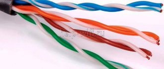
It got its name from the building. Inside there are copper wires in a sheath, twisted in pairs. Twisting is done with a certain step depending on the number of such pairs. The whole point of such twisting is mutual cancellation of interference to improve the quality of the signal in the working network (after all, this wire also carries electricity, although not 220V, and reliability here is needed at a high level, but this is a topic for standards).
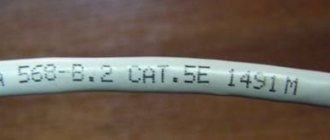
There are several types of twisted pair... Even many. The main classification is by device, not the main one - by protection. When installing at home, you will usually be dealing with a category 5 cable (if you want, look for it yourself, that’s not what the article is about).
In terms of protection, there is also nothing difficult - there is with protection, there is without protection. Protection does not mean from falling stools, but from the same interference that creates interference. This is usually not required at home, but you never know what you can get your hands on. The section is larger for the fact that you will have to open the cable during crimping, and you need to be prepared for anything) So a little anatomy for the system administrator and the home enthusiast to surf VKontakte.
So, there are pairs of wires inside - usually 2 or 4. The wire can be protected - we are talking about foil or braid. In this case, protection can be either for the whole wire or separately for each pair. There are a lot of subtleties, it’s better to open it right away and look locally. In home cable there is usually nothing like this - one braid, and there are pairs in it at once.
Twisted pair markings:
- UTP – regular, without protection, for home. If you need to restore a piece of your house and go to the store, just look for something like UTP5 - it will do just fine.
- FTP - with foil, also sometimes used indoors.
- SFTP – metal braid, used outdoors.
- STP – protection on each pair. When the wire is on the street near power lines (I hope you didn’t get caught there).
In total, the different options are arranged in the following figure:
An additional bonus is that there are multi-core and single-core cables. Stranded ones are used at home - the wire comes out flexible, just for active movements. It is better to use a single-core wire for industrial installation - up to the socket, the wire does not bend, but the signal transmission is much better.
I don’t even want to mention flammable and non-flammable, round and flat here - after all, this is not a system administrator’s textbook, but simply helping those in need at home. So if you have questions, run to the comments.
Attention! Leave your comments. We will help everyone!
Types of cables for the Internet
Shielding provides better protection from electromagnetic interference, both external and internal, etc. The entire length of the screen is connected to a non-insulated drain wire, which unites the screen in case of division into sections due to excessive bending or stretching of the cable.
- Unprotected twisted pair (UTP - Unshielded twisted pair) - there is no protective shield around an individual pair, most often this is UTP category 5 and higher;
- Foil twisted pair (FTP - Foiled twisted pair) - also known as F/UTP, there is one common external shield in the form of foil;
- Protected twisted pair (STP - Shielded twisted pair) - there is protection in the form of a screen for each pair and a common external screen in the form of a mesh;
- Foil shielded twisted pair (S/FTP - Screened Foiled twisted pair) - an external shield made of copper braid and each pair in a foil braid;
- Unprotected shielded twisted pair (SF/UTP - Screened Foiled Unshielded twisted pair) - double external shield made of copper braid and foil, each twisted pair without protection.
Useful: Pinout, connection diagram and checking the VAZ ignition coil
Wire selection and standards
In the last section I mentioned the categories of twisted pair, here we will consider this point in a little more detail. After all, the anatomy and transmission speed on the cord also depend on the category.
I recommended that you take category 5, but category 6 (CAT5, CAT6) is also suitable. All options are shown in the following table:
It will be important to choose a cable for the required speed. And this also depends on the number of wires inside. It usually happens like this:
- 2 pairs (4 wires) – up to 100 Mbps
- 4 pairs (8 wires) – from 100 Mbit/s
Typically, ISP technology limits you to 100 Mbps internet speed. But soon this threshold will be passed. What do I mean - usually there will be exactly 2 pairs on the Internet cable, but on home cables (from the router to the computer) there are already 4 pairs.
4 pairs, or 8 wires
Crimping twisted pair 4 cores diagram
The arrangement of conductors in the connector for a cable with 4 cores (2 pairs) stands out. In this case, the first 3 cores are placed similarly to the 4-pair circuit, and the last one takes place in the sixth pin (position) of the connector.
Crimping diagram for twisted pair 4 cores
The main problem here is not to make a mistake with the placement of the last wire. One way to avoid this is to insert it after the previous three.
Crimping theory
And now we are approaching the crimping procedure. But there is still something to clarify, the final frontier.
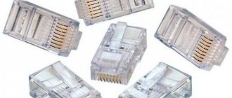
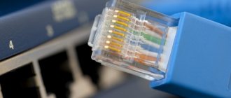
You have all seen the connector at the end of a twisted pair cable, which also goes into the network connector of a network card or router. This plug has a special marking. The one that is mainly used now in the home local network is RG-45. A little about the connector design and connection.
- The twisted pair is installed in the connector socket.
- The twisted pair wires are routed through special grooves in the connector.
- The contact mechanism of the connector is knives. In store condition, they are separated, providing a path for the cable wires.
- When crimping, apply pressure to the knives, and they cut through the sheath and ensure tight contact with the wire cores.
- On the other hand, the contacts of the knives remain open - they provide a connection to the network adapter when connected.
Here is a picture of how the knives work:
And here is the connector in an enlarged view (the same wire tip or “jack”):
This connection is reliable and transmits the signal perfectly. But beginners may not be able to do enough at first - and either there will be no connection, or it will be established at a low speed (this is one of the reasons for the decrease in speed on the network). The best way to fix it is to squeeze it harder again, or re-press it again. In practice, at our university this procedure did not work out for everyone the first time - so everyone starts somewhere.
Application of non-standard pressing methods
Considering that purchasing a special tool (the same crimper) requires money, some craftsmen practice a non-standard method of crimping wires. Use a regular electrician's screwdriver with a flat blade of suitable width and thickness.
Using such a screwdriver, the contact rods are pressed, sequentially pressing one at a time into the body of the plug.
The method with a screwdriver is “barbaric”, I must say, but it works. True, the quality of pressing is not always good, resulting in unstable operation of the network cable
The procedure for crimping the copper cores of a network cable can be studied theoretically without much difficulty. Meanwhile, even with theoretical knowledge, practical skill is required .
In fact, this skill is developed quite quickly even when you have to deal with work for the first time. True, a novice master cannot do without ruining a couple of plastic forks - he will have to practice first. This is the law of practice.
Tools
The main thing when crimping is to make a high-quality cut with knives on the shell. And for this you need to create the right strong pressure on the contacts. Well, we couldn’t do it without creating tools, although we can do without them.
Pros use a special tool - crimping pliers, or crimper. I’ve also seen names like “wire crimpers” or “connector crimpers.” Here, who already has what taste, you will probably hear some other versions.
This thing isn't that expensive. You can find a working copy for less than 1000 rubles. For a one-time repair at home, the thing is useless. But their main feature is their functionality tailored for twisted pair cables:
- Cut the braid exactly to the level of the wires
- Stripping wire insulation down to the core
- Simultaneous crimping of all knives with the required force
- Sometimes there is a socket for crimping and telephone cable (RG-11)
This is what they look like:
How to make twisted pair installation easier: secrets from practice
It is worth noting some other subtleties of twisted pair installation:
- To measure 1 meter of cable it is not necessary to look for marks on it. A length of 1 meter is the distance from the fingertips to the opposite shoulder along the chest line of a person of average height.
- The cable sheath must fit into the connector and be crimped. This helps prevent accidental disconnection of the connector. If you remove too much casing, try stretching the rest. Please note that this does not always work in cables with a thick sheath.
- After installing the twisted pair connector, make sure that all wires are inserted into the connector until they stop. Gaps lead to poor contact.
- Use twisted pair testers to monitor the quality of connector installation. Often the simplest models are sufficient. More advanced devices allow you to collect the maximum available information and even draw up a small report.
LAN tester for twisted pair: advanced model from Softing
- If the situation requires connecting cable cores using twisted pair tapes, it is advisable to stock up on a special tool - crimpers for push-button connectors. Unlike pliers, they do not harm the connectors and significantly speed up the installation of adhesive tapes.
- If you are crimping an FTP/STP cable with shielded twisted pair connectors, it is recommended that you first prepare the wires for installation as for a UTP cable, and then cut off more of the sheath and crimp the intact shield.
- Remember that although the cross-section of the twisted pair core is about 0.5 mm, its use as a conductor is allowed only in low-current systems. It is strictly prohibited to use twisted pair cables to power active equipment.
A set of tools for working with twisted pair cables
And one last thing. If you often have to work with twisted copper cable, collect your own set of tools or take a ready-made set of tools for the system administrator. You can take a ready-made one or assemble the components of the kit at your discretion.
No tool
In my life I have seen many crimping methods. But the most interesting of them was teeth, because... a person’s mother-in-law was a dentist... So sometimes you don’t even need a tool at all.
Another handy tool that everyone has is a screwdriver. Moreover, this is perhaps the most popular tool at home. The main thing is not to break anything and push through the contacts efficiently. If the connection is not established during the test, you just need to try again. The working method is difficult, everything constantly slides off - but without fish there is fish.
Another home helper is pliers. But my advice is that it’s better to suffer with a screwdriver. The pliers do not provide strong indentation (especially in the middle), and with great Russian heroic prowess they easily break the connector into small pieces.
Crimping diagram - pinout
And now the science itself. It’s one thing to apply pressure, another thing is to correctly insert the wires into the cores (and this is the most important thing in order to correctly crimp a twisted pair), and into both connectors - a random set will not work here. The order is very important. In total, the connector has 8 grooves for 8 cores. If 4-core wires are crimped, some of the grooves are left empty, the main thing is to get it right.
First, let's look at the classic crimping of an 8-core wire. There are 2 ways:
- Direct cable crimping (type B, 568B) is used in 99% of cases. Used to connect peripheral devices to a router/hub/switch.
- Cross crimp (crossover, type A, 568A) - used for direct computer-to-computer connections.
For reference . Now modern adapters understand both of these methods, but the first option of direct crimping remains preferable.
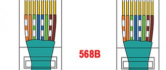
The names of twisted pair crimping circuits are taken from the way the wires are arranged in relation to each other. Look at the images below and you will understand everything. The main thing here is a view of the connectors from below (where there is no leg).
Direct crimp
Use this pinout diagram!
If the pictures are suddenly unavailable for some reason, the arrangement by color is:
1. White-orange 2. Orange 3. White-green 4. Blue 5. White-blue 6. Green 7. White-brown 8. Brown
Cross circuit
Four wires
Another option for 4 cores is the case when there are only 2 pairs. This is how they usually do it:
The whole point of proper pinout is to match the wires on both sides of the cable, without even knowing how the connector on the other side was crimped. An unspoken standard where you don’t have to run to the provider’s shield. The numbers 1-8 in the pictures are sometimes squeezed out on the sockets, this is for those who do not want to confuse the order.
Step-by-step instructions for crimping a network cable
Considering that cable connections are used quite often in a variety of conditions, including domestic ones, the question of how to crimp a cable onto 8 cores is quite relevant. Moreover, if not specialists are taken into account, but ordinary users - owners of personal computers.
Let's look at this simple process to make things easier for potential home network circuit builders.
To perform twisted pair cable crimping work, you will need a special tool:
The first two tools with exotic names are a special press, reminiscent in design of ordinary electrician's pliers and a cutter for removing cable insulation.
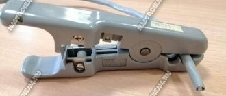
In essence, a cutter is an ordinary knife, with the only difference being that it is additionally equipped with recesses for removing the insulating coating.
A professional press used for crimping copper cores of network cables. This tool configuration allows you to work with 8P8C and 6P6C series plugs
Step #1 - cable preparation
Here you will need to select the desired option based on the number of cores and the required length. For home use, it is often necessary to crimp a 4-core copper twisted pair, that is, you need a piece of cable with four wires.
In principle, the use of an eight-core cable design cannot be ruled out. In this case, unused pairs are simply not used. Another issue is savings, because the price of four-pair products is higher than two-pair ones.
A fragment of a network cable, where eight copper cores are placed under the sheath - four twisted pairs. This option is often suitable for solving connection problems in domestic conditions.
Step #2 - trimming the insulation
Having prepared a piece of the required length, you must carefully remove the insulation on the short end sections of the network cable. It is enough to retreat 40-50 mm from the edge of the end cut, then cut the cable sheath with a light circular pass.
Trimming the sheath of a network cable using a shaped cutter specially designed for such purposes. As you can see from the picture, the tool is equipped with different shaped cutouts that provide better cutting quality
It is recommended to perform this step carefully so as not to damage the insulation of the internal conductors. Usually the shell is not cut to its full depth, but only partially. Then, with a smooth movement of the hands, the cable is bent in the area of the cut, due to which the sheath is torn in a circle.
It is quite convenient and high-quality to remove the cable sheath using a stripper. However, first you will have to spend some time mastering this tool. Even professionals are rarely able to perform high-quality removal with a stripper on the first pass.
Step #3 - preparing the cores for loading the fork
Opened, twisted-in-pair conductors in the area freed from the insulating cable sheath should be unbraided (untwisted) and smoothed. Copper conductors in thin insulation are quite soft, so performing such actions is not difficult.
Then all the wires should be aligned relative to each other and cut exactly perpendicularly, 2-3 mm away from the end. This operation can be conveniently performed with ordinary paper scissors. The result should be an even end row of four (or eight) insulated copper cores.
Before loading a plastic plug into the body, the lined up row of conductors must be trimmed to obtain an even end line of the entire row. It is convenient to trim with ordinary scissors
Next, a new plastic plug with eight pins (8P) will be used, on which crimping will be performed - contact fastening of the copper conductors. It is worth considering that there are no 4-pin plugs for computer networks. Therefore, in any case, an 8-pin plug is used.
Step #4 - crimping the pads
The back of the plug (8P) is technically the entry gate for loading the copper cores. A kind of gateway contains eight rectangular cells into which conductors corresponding in color are loaded.
Loading the copper cores of the network cable into the “gateway” of the contact plug is carried out without removing the insulation. The wires are simply inserted into the channels until they stop.
Then a standard 8P8C connector press is used. The press block is placed on a plastic fork, after which the tool handles are compressed until a characteristic click occurs.
The moment of crimping the contacts of a plastic terminal plug using a special tool - a crimper. It is recommended to press the cable towards the plug with your free hand until the process is completed.
Step #5 - testing the quality of the press
After crimping, the press is removed and the connection is checked for strength by attempting to physically pull the conductors out of the plug. If everything is done exactly according to the technology, the crimp strength will not allow the cores to be removed from the pressed slots.
At this point, the crimping procedure is considered complete. A similar process is carried out at the opposite end of the cable.
The completion of crimping the two ends of the cable is usually accompanied by a subsequent electrical test. For this purpose, a special tester is used, which includes a transmitter and receiver of the test signal. The treated cable is included in the device and is tested for integrity of connections using control LEDs.
A device for specialized testing of the quality of electrical communication of crimped conductors. Usually used at a professional level. In everyday life, you can use a simple cable testing technique
Crimping procedure
Now let's move on to the correct way to crimp the cable. Be careful when working - the main thing is not to damage yourself, and the connectors are cheap)
Step 1. Remove the insulation
First, remove the insulation from the wire - you can carefully pry it off with scissors or use a stripper on a crimper - insert it, turn it, and the wrapper comes off. It is fragile and can be removed quite easily. You don't need to remove much insulation - a couple of centimeters from the end is enough. If anything happens, you can trim everything later. The pliers have special marks indicating at what level the coating should be cut.
Step 2. Straighten the wires
Now we take our wires, straighten them and arrange them according to the pinout diagram. From the recommendations - try straightening them with a pencil or hand - they become smooth and closely spaced to each other - which is what we need.
Step 3. Trim
Now is the time to cut and straighten our wires. We cut it either with wire cutters, or with the same pliers, or even with a knife. Leave about a centimeter of clean wire. With practice, you will learn to accurately check the distance.
Step 4. Getting into the connector
The hardest part. Now we need to insert our design into the connector. When inserted, the connector is positioned with the leg down. Why is it difficult - the wires try not to fall into their grooves, they crawl into neighbors, bend, and get tangled. Here the recommendation - patience and once again paying attention to the pencil treatment - helps.
Step 5. Insert all the way
After the hit, we press on the cable so that the wires go all the way. In this case, the wrapper will be hidden in the connector itself. If the wrapper does not fit into the connector, fractures are possible in the future. If the opposite turns out to be short, the wires will not reach the knives. So everything is done with experience and by eye.
Step 6. Crimping
Now is the time to tighten our knives - the methods were discussed above, but it is better to use pliers. Take it and live it.
Step 7. Check and refinement
Be sure to check the connection on your computer or router before putting away your tools. Sometimes it may not work out the first time. The easiest way to correct the situation before getting upset is to squeeze the knives again, but harder. It helps a lot.
If there is no connection, pay attention to this:
- Are the wires routed exactly according to the diagram? Didn't they fly out? Look through the connector.
- Have the wires reached the stop of the connector? Were the knives able to reach them?
The rest can only be attributed to cable failure.
Initially, before crimping the network cable, you can install these casings. They perfectly protect against bending near the connector, but in practice everything works without them. There are a lot of species, that’s not what the article is about. For reference.
Technology of cable routing in the socket
Pinout of an RJ45 socket does not require any specialized equipment; you only need one tool - nail scissors or a small knife with a thin blade. Here is the sequence of actions:
- The top layer of the winding is cut off. The cut length is about 10 cm for ease of wiring.
- The twists of all pairs are unwound and the wires are aligned so that from the base of the top layer to the tips of the wires they do not intersect.
- Any socket has two color markings. “A” – cross connection, “B” – standard connection. According to the last marking, the RJ45 pinout is carried out.
- Having attached the base of the braid to the board, first the cores are inserted into the far connectors. Be sure to check the cable tension so that the distance from the braid to the clamp does not exceed 3 cm.
- Having secured the cable cores in the required connectors, crimping is performed. Holding the nail scissors so that the angle of the cutting guides is 45 degrees, you need to press on the core from above until you hear a characteristic metal click.
When installing a power outlet on a wall, the connectors should always face down. This protects the contacts from becoming clogged with dust and moisture, and when you quickly connect the cable from below, there is less chance of accidentally knocking down the socket on the wall.
Examination
There are also options to check the cable connection. The key is to get both ends. In practice, this does not always work out at home - after all, the provider will not give you his end of the line. Therefore, it’s easier to check on the device - if everything works, then it’s great. No - we are looking for a different reason.
LAN testers are used professionally. This device shows for sure which vein has a signal and which does not:
Additionally, you can use a multimeter, but here you will have to ring each wire separately. But what can you do, because Russian people can do everything)
Thank you all for your attention! If you still have questions, write in the comments. We press, we press and we will press)
How to check the quality of work performed
After all devices are connected with prepared wires, you need to check the quality of the line. It is enough to connect the Ethernet connector with a network cable to a laptop or PC. If the installation is done efficiently, everything should work smoothly.
Professionals check wires with cable or LAN testers. You need to turn on two units and diagnose the cable. Each such device has ports for connectors. Special LEDs report the status of each core. Therefore, if there are breaks, it is clear where exactly the wire was crimped poorly.
Those who do not have special tools can use a multimeter. The device is set to low resistance or ringing. Next, check all the wires with a multimeter. Small probes will be required. This will allow you to touch the contacts accurately. You can sharpen the tips or put wire on them.
It is not difficult to check a cable whose ends are in different rooms. There is a coil in the ports of devices connected by wire. It connects one pair and creates conductivity.
You need to install a connector into the port of the connected device. Conductivity is checked at another connector. If a private line is used, only two pairs need to be tested.
The resistance should be approximately the same everywhere. If in some pairs the difference is significant, the crimping was performed incorrectly. The same conclusion can be drawn when the line does not “ring.”
