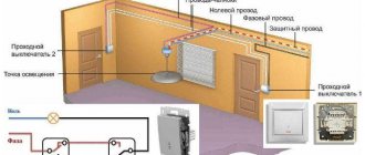
Switch types
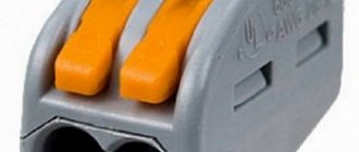
There are two ways to connect wires to a light switch: screw terminals and self-clamping terminals. In the first case, the cables are placed in a special block and secured with a screw. The only drawback of this connection is that over time the screws become loose and need tightening. Those. A mini-circuit can occur at any moment.
Large manufacturers use the second option to create their products. It is considered more expensive, but also more effective. In addition, recently modular technology has become increasingly used.
Diagram: example of connecting a two-key switch
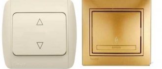
Three mounting options for single-key switches
Let's look at three switch connection diagrams that are similar in design (have one button), but differ in the type of installation. Also, all options are united by the basic law of introducing single-key models: the dynamic element opens the “phase” and not the “zero”. Otherwise, there may be a risk of injury during repair work and even when simply replacing lamps.
#1: Photo instructions for installing an outdoor device
The location of the wires for this connection diagram is not of fundamental importance: they can run along the surface or be inside the wall. An external type of switch in a residential area is welcome if expensive repairs have just been made and there is no desire to tear down the walls and install ducts again.
The simplest connection diagram for a single-key switch, which serves as the basis for practical actions for novice electricians: wire L (phase) goes to the switch, the rest - directly to the light source
We will consider the option of external cable laying, in which the wires are enclosed in a corrugated protective channel.
At the location where the switch is installed, the corrugated pipe, fixed to the wall with special clips, is cut across, and the working insulated wire is taken out.
Under the switch there will be another electrical device - a socket, so the cables for both devices are enclosed in one corrugation for aesthetic reasons.
The power cable associated with the outlet will pass through the surface-mounted switch, so as not to make a loop and not to increase the installation area
The selected switch model - Schneider Electric - has a plastic case and IP44 protection degree. Before installation, we take safety measures: turn off the power to the cable at the electrical panel installed on the site or in the corridor.
To make sure there is no voltage in the cable, use an indicator screwdriver. When the issue of turning off the power is resolved, we begin disassembling the switch.
First, we take out the key with our hand - this is done quite easily.
Under the key that closes the switch from above, there is another plastic protective strip - the front panel, which also needs to be removed by carefully pressing out the holders
The next step is to remove the working mechanism.
The mechanism that closes/opens the electrical circuit is not secured with special holders or springs, so it can be reached quickly and without problems
Now you need to accurately determine the location of installation of the switch and mark on the wall the points for screwing in the fasteners. To do this, take an already empty case and attach it to the wall.
We level it and use a marker to mark the points for drilling. Using a drill, we drill holes for fastening (another fastening method is also possible).
We fix the plastic case in a designated place on the wall using dowels - the best option for fixing on concrete and brick bases
We remove the elastic plug located in the upper part from the switch body, insert the wires into the hole and the end of the corrugated pipe coming from the ceiling.
The result should be a neat, tight connection between the corrugation and the body with free access to the wires for further work.
Time to start connecting directly. We remove the insulating material from the ends of the wires and strip 8-10 mm.
We connect the white wire (phase) to the terminal marked L, the blue wire to the other terminal marked “1”. Carefully tighten the bolts and place the working unit into the housing.
We lay the wire leading to the socket around the working unit and bring it out into the lower hole of the housing, and insert the second end of the corrugated pipe there
We reassemble the switch: put the front panel in place, then fix the key.
At the end of the work, we carry out testing: turn on the power supply and press the key several times. If the lighting device lights up when turned on, the connection is made correctly
It is quite easy to install the switch yourself, even if the installation is complicated by the presence of additional devices.
However, if you are not sure of the correctness of actions, it is better to play it safe and make the first connection under the supervision of an experienced electrician.
#2: Master class on replacing an old switch
Often, in connection with renovations in an apartment or private house, it is necessary to dismantle the old switch and install a new, more modern and convenient one in its place.
Let's look at the main stages of replacing a switch using step-by-step photographs of the process.
Before us is an old, unsightly model of a built-in switch installed inside the concrete base of a panel house. It is necessary to remove it by unscrewing the two mounting bolts
Using a screwdriver, unscrew the screws and remove the plastic cover.
Under the cover is the old connection mechanism, in which the cores are fixed with a bolted connection. Bolts are visible on the left, and metal fastening “ears” on both sides.
Our task is to determine the “phase”.
To find the working wire, we use a voltage indicator, which is usually an indicator screwdriver with a light signal
We bring the screwdriver to the contacts one by one, never touching them with our hands (it is better to use insulating gloves). For an accurate determination, set the key in both positions.
When the “phase” position is off, only one contact will be energized. The second wire is for the lighting fixture.
Having established the purpose of the wires, we turn off the electricity supply, check the presence or absence of voltage and, having made sure that it is safe, we begin to disassemble the old switch. We unscrew the fasteners of the metal holders (“claws”) and take out the working unit.
Carefully disconnect and isolate the wires: first the “phase”, then the second wire. For insulation, it is better to use electrical tape of different colors so as not to make mistakes when connecting
We finally release the mechanism, straighten the wires - the place for the new switch is prepared. We take a new product, purchased in advance, and prepare it for installation, in other words, we disassemble it.
We remove the key, unscrew the protective panel and see the internal mechanism - with two mandatory clamps and spacer holders.
The screws located at the edges regulate the movement of the “legs”, and those located on top are used to connect wires - they are the ones that regulate the contact pressure plate
We strip the ends of the wires about 1 cm, insert them into the holes located under the upper screws, making sure that the winding does not slip inside along with the exposed wire. We tighten it tightly so that the wires do not move.
If the holes are marked, insert the “phase” into the hole marked “L”, the outlet wire – “1”. Instead of the indicated designations, there may be numbers “1” and “2” - then the “phase” will go to “1”
Having connected the wires, we insert the working unit into the installation box.
To prevent the mechanism from “walking” inside the socket, we fix it using metal holders, tightly tightening the side fastening screws
Install the top panel and fix the key.
We test the operation of the device, although it is better to carry out the first check before the internal mechanism is fully secured - so as not to have to redo it
So, to install the new switch we needed tools (screwdriver, pliers, knife, wire cutters, indicator screwdriver), some insulating material and 20 minutes of time. Calling an electrician would cost about 500 rubles.
#3: Connection diagram with junction box
When you get bare walls, which is common in new modern standard houses, you have to install interior doors, lay floors, and tidy up the walls yourself.
Electrical wiring is no exception. Therefore, let's look at how to properly connect a switch along with a lighting fixture, a circuit breaker and a junction box.
You need to start by choosing a connection diagram. In the picture - the simplest one, with one light source, a single-key switch and an exit to the panel; we will complicate it by installing automation
Our goal is to install all the devices in their designated places and connect them to each other with wires without confusing them. We try to install the distribution box in the center.
The open or closed method of cable installation does not fundamentally affect the arrangement of circuit elements.
As a result of the preliminary installation, the following diagram should be obtained: automatic unit + distribution box + mounting box for the switch + output to the lamp + three-core cable with a cross-section of 1.5
First of all, we connect an automatic protection device that protects the network from overloads and power surges.
Let's decide on the color of the wires that we will need to connect the switch:
- white – phase;
- blue – zero;
- yellow – earth.
We strip the wires and insert them into the terminals intended for them. We use the yellow wire for grounding, fixing it separately with a special clamp.
The three-core wire is considered to be universal. To connect a lamp, a two-wire one would be enough, but it is better to predict events and, just in case, prepare wiring for connecting 2 devices or a chandelier
The role of the lamp will be played by an ordinary socket and a light bulb (incandescent, LED, energy-saving).
We strip the wires and connect them to the socket, inserting them into the holes provided for this purpose. Carefully bend the yellow wire and insulate it
We bring the wires into the installation box to install the switch.
When connecting the switch, the yellow wire is also not useful. We clean the other two, isolate the yellow one and bend it to the side
Modern models of switches have marked terminals, which makes it easier to fix the wiring. We insert them into the required holes and secure them with screws.
After connecting the wires to the switch mechanism, insert the working unit into the mounting box, put the housing on top, and fix the key
All elements of the circuit are connected, all that remains is to connect the wires in the junction box.
We remove the insulation, strip the ends of the wires, twist them first with our hands, then with pliers. We make the connection according to the colors according to the drawing, remove the uneven ends with pliers
We check the correctness of the connections with an indicator screwdriver and test - press the switch button.
If the light comes on and goes off under the control of the switch, all steps have been completed correctly. After turning off the power, hide the wires and close the junction box
As you can see, you can complete the entire connection diagram yourself using a minimum of simple tools.
How to connect a switch
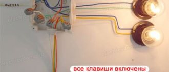
Below we have presented a diagram of the operation of the switch and its installation. A two-key Euro switch is two single devices, but in one housing. Their phases are combined, and at the moment when one bridges its contacts (and it begins to supply power to its group of devices), the second breaks the circuit and stops receiving signals from the phase cable from the outlet or wiring in the apartment. This happens because the ground wire and phase neutral are connected directly to the lamp, and the phase passes through the switch.
Connection diagram for a two-key switch to a chandelier
To work you will need:
- Pliers;
- Screwdrivers (indicator, flat and Phillips);
- Stationery knife;
- Level.
First we turn off the electricity. Next, you need to prepare the wires in the installation box; to do this, we clean them with pliers. It is necessary to leave approximately 10 centimeters of wire; cut off the excess with a stationery knife. Now you can connect the wiring and switch wires. If the wiring is three-phase, then this process will not be particularly difficult.6 We simply connect the cables corresponding in color to 3 phases and zero.
Double switch
If the wiring is two-phase, then you need to fasten the wires of the switch with a terminal, and eventually getting two jokes instead of three, connect them to the power supply of the electrical network.
Install the protection plates and turn on the power. Ideally, both switches should be in the up or down position when the light is off. If necessary, remove the second electrical switch, rotate it 180 degrees in the box, then set it as two toggle positions.
Video: How to connect a two-key switch
Connecting a chandelier is also no more difficult. Certain lamps are combined into groups, and if there can be only two groups, then there can be any number of lamps: with two arms, five or even six.
Comb bus for connecting group circuit breakers
In old apartment electrical panels, group circuit breakers were combined using jumpers. The method is cheap, accessible, but not reliable. Today, a connecting bus is used for similar purposes. This simplifies electrical installation and makes the wiring look neater.
Varieties of combs
There is no universal connecting bus suitable for any circuit breaker. The machines have different dimensions, number of pins and other characteristics. Therefore, combs come in a wide variety.
Based on the shape of the contacts, there are 2 types of comb busbars:
- Pin (toothed). Universal contact suitable for any machine.
- Forked. Used where the tire needs to be clamped under screws.
The combs differ in length, that is, in the number of machines that can be connected to them. If necessary, a tire that is too long can be shortened with a hacksaw. But it is preferable to use products for a standard number of machines:
- 12;
- 24;
- 36;
- 48.
There are also differences in the number of connected phases. From this point of view, connecting busbars are of the following types:
- Per 1 pole (1P). Used to connect single-phase group circuit breakers.
- 2 poles (2P). RCDs, automatic circuit breakers and any other devices that require a phase and zero connection.
- 3 poles (3P). Used to connect three-phase group circuit breakers.
- 4 poles (4P+N). Three-phase machines and devices that require a neutral wire to operate (three-phase RCDs).
Pin connection bus for three-phase network
Important! If you had to cut one large tire into several small ones, then you need to pay attention to the resulting cut. Individual conductors must not be bent or shorted together. After cutting, you need to remove copper dust from the comb.
Design
The combs have a prefabricated design. The structure is based on a flat copper busbar. It has bends for installation on machines. Depending on the number of connected phases, there are 1 or 4 buses in one comb. They are insulated with non-flammable plastic. Usually white or gray.
The design is made in such a way that when assembled there are practically no exposed conductive parts. This increases the safety of operating personnel. And the junction box becomes less susceptible to dust.
Form of conclusions
The most common are comb buses with pin taps (pin type combs). The English name is pin. They fit most modern circuit breakers. The terminals of such tires are more difficult to bend during transportation. Therefore, during installation there are fewer problems with installing circuit breakers into the holes.
The second type of bends is fork-shaped (fork type). They are used relatively less frequently. Not suitable for all types of modern equipment. Connecting bars with forked terminals are not recommended for use with powerful loads. Usually they are placed in a panel with a maximum current of up to 63 A.
Double-pole fork-shaped comb
Pros and cons of connecting busbars
Comb connectors are replacing classic wire jumpers from the practice of electricians. This is explained by the advantages that they have in comparison with outdated installation methods:
- Connecting machines is an order of magnitude faster. It is much easier to insert and tighten the comb than to sit and cut the jumpers by hand.
- More reliable contact. By increasing the contact area between the terminal block of the machine and the comb output.
- Double reduction in the number of contacts inserted into the machine. Instead of 2 wires from the jumpers, you need to insert 1 pin from the comb. This factor increases the reliability of the junction box.
There are also disadvantages:
- When repairing the contact connections of the machine, it is necessary to remove the entire comb. Otherwise, the switch will not be able to be pulled off the DIN rail.
- To install additional circuit breakers, you will need to purchase a new longer busbar. Therefore, it is better not to use the comb on temporary equipment or to immediately install additional modular devices for the future.
- Price. Old jumper wires are practically free. They can be made even from scraps of wires lying around under your feet. You will have to buy a comb tire in a store.
Connecting machines with wires is cheaper
Additional Information. The comb requires periodic inspection and maintenance. It is important to pay attention to the temperature and color of the connector and, if necessary, tighten the screws of the circuit breakers.
Connecting machines via a comb
When using a comb bus, circuit breakers are connected in a parallel connection. If the comb is designed for 1 pole, then 1 phase is suitable for each machine. Such a connector is usually called a phase connector. It is located at the top of the line of switches. There is 1 common incoming wire to the comb. She multiplies it into separate group machines.
If the bus is two-phase, then the machines receive a phase and a zero. In this case, two-pole protection devices are required.
Installation rules
When installing connectors, you must follow the electrical regulations applicable to such devices. This increases the safety and reliability of electrical equipment. The basic installation principles are:
- Before installing the comb, it is necessary to ensure the mechanical integrity of the interphase insulation. Test the terminals with a multimeter for short circuit. This will reduce the risk of phase-to-phase faulting.
- The plastic protruding part of the comb bus should be located on the lever side of the machine and completely cover the conductive parts. The comb is installed so that the copper leads are inaccessible for touching by service personnel.
- Some models of circuit breakers have 2 types of terminal blocks. Some are designed for connecting pin combs, others for fork combs. Before installation, you need to find out what exactly you are dealing with.
- Fork combs are used at currents up to 63 A. Overloading the product will lead to heating, melting of the insulation and phase-to-phase short circuit.
Connecting single-phase devices
Single-phase connection is the simplest. It is used for single-pole machines. The procedure is as follows:
- All protection devices are installed in a row. This requires a DIN rail.
- For each individual device, the screws in the terminal blocks are loosened to a certain point. This is done from the top side.
- One single-pole bus is inserted into the terminal blocks of circuit breakers. The pitch of its teeth should be 17.5 mm.
- The screws are tightened. The tightening is tight enough to securely fix the tire pins.
Connecting RCDs and differential circuit breakers
To connect single-phase RCDs and differential circuit breakers, you will need a double-row comb bus. It must be installed at the top of the protective devices. One bus is considered phase. Its pins should be connected to the L terminals of the RCD. The second bus is zero. Connects to N pins.
When assembled, the line will alternate between phase and zero. And the distance between the individual pins of one bus will be twice the width of a conventional circuit breaker, that is, 35 mm.
Connecting three-phase circuit breakers and RCDs
With three-phase protection devices you will need a 3 or 4 pole comb busbar. A four-pole comb is necessary when, in addition to 3 phases, a neutral wire is also used.
Switch installation
The main difficulty is not connecting the wires to two independent lamps. And in installing a switch in a junction box. Imported switches (simon, wessen, lezard, schneider electric, anam, legrand-legrand, valena).
You need to use a screwdriver to secure the switch directly in the installation hole and tighten it with screws or bolts (which are most often included in the kit). Then we install the box with the keys on it, press it and secure it (if necessary), with bolts on top.
A very interesting practice is to install a switch with an indication of hidden installation. This type of electrical appliance is popular in a “smart” home and apartment, where design and style play a big role. Its installation is carried out in a recess in the wall, from the junction box to the wiring cables, everything is completely similar to conventional installation, but at the final stage you need to attach a special closing cover (sometimes sensors with a flip flap are used).
Let's consider the installation process if there are two electricity networks. We combine one network into one group, the second into another. Now we connect the cables accordingly. One wire should close when the other opens, so check the connections carefully.
Features and design of a two-key switch
There are a huge number of switches equipped with two keys, but in practice this is not the only criterion. Since similar features are inherent in some types of pass-through and crossover switches. Therefore, in order not to get confused in such devices, it is necessary to understand in detail their design and functional features.
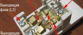
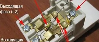
The main task of a two-key switch is to divide the supply conductor into two independent lines, switched by two separate keys. Therefore, when you connect the device, you will find three pins on the back, as shown in Figure 1 below:
Rice. 1. Features of two-key switch
The three clamps are for:
- 1 – transmission of electricity to the first group of lighting equipment;
- 2 – transmission of electricity to the second group of lighting equipment;
- L – used to connect the phase conductor from the electrical wiring;
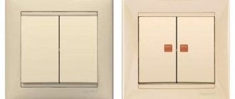
On the switch body itself there is also a diagram of a two-key switch, which shows the principle of operation and switching of contacts.
Rice. 2. Two-key switch design
Structurally, a two-key switch consists of the following elements:
- Keys – designed for manual control of the switching process. In accordance with clause 10.2 of GOST R 51324.1-2012, they are made of insulating material to prevent contact of human hands with live parts.
- Contact group switch - moves the switch contacts to the on or off position. Each switch in a particular model is designed to allow direct connection to a key.
- The switch module is the main block of the switch, containing the contact group and the mechanism that sets them in motion.
- Latch – in this model it is made as a separate part and is used to fasten the false panel to the switch module. It can also be made in the form of locks on a module or false panels, as their integral part.
- False panel - used for decorative decoration of the switch. Can be selected according to color for interior design.
Some models may be equipped with a light indication of the off state. An LED is installed inside the switch keys themselves or in the false panel, which lights up in the off position. This option makes it easier to detect a two-key device in the dark, but makes its own adjustments when using LED and fluorescent lamps.
One switch for two lamps
As already mentioned, the devices control two groups of lamps, which means you can install the bathroom and corridor on a two-key switch. To do this, we bring the wires from both lamps to the wires and the location of the switch, combine each of them into separate groups, connect them with terminals and attach them to the switch. For large rooms, we recommend reading the article on how to connect a pass-through two-key switch.
Installing a light switch for two rooms is done in the same way.
Installation tips:
- combine groups thoughtfully (for example, kitchen-toilet, corridor-bath, living room-room, etc.) then there will be no cable overuse;
- install switches within easy reach: not behind a chair or cabinet;
- a more powerful switch must be connected to the lamp and fan, taking into account that in addition to the main cables, there is a wire responsible for powering the fan itself;
- We recommend using switches with simon indication;
- in order to connect the device correctly, you must look at the wiring layout, especially when connecting to two power sources;
- If you have not had such experience before, we recommend that you first watch a video of how to install the switch.
When choosing switches for lighting residential premises, we are always faced with a dilemma: should we buy a regular light switch, or one with backlighting? Any manufacturer, including the popular legrand, offers the same models, both with and without an indicator.
What is an illuminated switch for? This may sound strange, but for the cleanliness of the walls. Every time we feel the keys in the dark, we gradually grease the walls around us and create scuffs on the covering. The price difference is small, but connecting an illuminated switch obviously provides certain advantages. Why do many buyers prefer traditional models?
The fact is that there are common “horror stories” and myths about the negative aspects of backlighting
RCD differential automatic. switches
Differential circuit breakers Easy9 are one of the products in the new Easy9 line of protective and switching equipment from the recognized leader in the global electrical engineering market - Schneider-Electric. Along with automatic machines, the new Easy9 line includes:
Differential circuit breakers Easy9 combine the functionality of two protection devices at once - an RCD and a circuit breaker, thereby providing:
Protection of the electrical circuit from short circuit (circuit breaker function);
Protection of the electrical circuit from overload (circuit breaker function);
Protection of a person from electric shock (RCD function);
Protection against fire (RCD function).
Main features of Easy9 differential circuit breakers:
Reduced installation time. Diff. the machine provides the same protective functions as an RCD with a machine, while installing and connecting a differential circuit breaker takes much less time than installing and connecting the machine and RCD separately.
Saves space during installation. Differential machines 1P+ N are only 36 mm wide. This allows you to save at least 30% of space in the distribution board, in contrast to a circuit breaker paired with an RCD, which takes up 54 mm.
Simple, logical and large markings allow you to identify the Easy9 difavtomat among similar ones by reference, rated current, voltage and shutdown current. Also, each difavtomat has the corresponding certification marks, production date and barcode.
A convenient two-position latch makes installation/disassembly of the Easy9 RCD much simpler, more convenient and faster than installation of a conventional RCD, even with one hand.
The engraving of the neutral on the body of the difavtomat “N” prevents erasure of the designation and guarantees correct connection.
| Operating principle of RCD: | The RCD function must be checked regularly! | |
| By measuring the difference in current between the live conductor and the neutral conductor, a differential load switch actually detects the current flowing through the human body. | ||
| If this current reaches the 30 mA threshold, the differential load switch trips within a few milliseconds, thereby preventing personal injury or worse. | ||
Technical characteristics of Easy9 differential circuit breakers:
(1) — RCD type (or class) is a parameter characterizing the type of leakage current to which the RCD reacts. Today, there are RCDs with classes AC, A, Asi and B. RCD class AC is the most common and inexpensive type of RCD. RCDs of this class are used in general-purpose circuits without special characteristics. In such circuits there are only sinusoidal leakage currents, which RCDs of this type can easily cope with. If a load with single-phase power supply equipped with a rectifier (washing machine or induction cooker) appears in the circuit, then pulsating DC components appear. To protect against them, it is necessary to install a Class A RCD, because An AC class RCD may simply not work. Class A RCDs protect against larger types of leakage currents, but also cost about 20% more. Other types of RCDs are extremely rare.
“Horror stories” and myths about the illuminated switch
To understand the so-called "problem", let's look at the different types of indication. It comes in neon and LED. There is no fundamental difference in power consumption; both schemes consume no more than 1 W of power. Neons come in two colors: orange (red) or green, depending on the gas in the bulb. The LED can be of any color, even dynamically changing hue (RGB).
- Additional electricity consumption . This statement is partly true. The LED backlight circuit consumes about 1 W of energy. In a month, it accumulates 0.5–0.7 kilowatt/hour. That is, you will have to pay a couple of rubles for comfort (from each switch). Neon lamps have similar costs. There, the energy is spent mainly on the limiting resistor.
- “ We installed the backlight - now the switched off lamps glow in the dark! " And it is true. Old-style lamps (incandescent and halogen) go out regularly when turned off. But no one uses them anymore. The problem concerns economical fluorescent gas-discharge lamps (they flash periodically), and LED lamps with an inexpensive control circuit (weak glow).
Two-gang switch with backlight SE Unica, white
By submitting data, you agree to the privacy policy.
By submitting data, you agree to the privacy policy.
Ways to receive orders
Pickup in Moscow - more details.
— Moscow, Novokhokhlovskaya str., 91, building 10
.
— Moscow, Malomoskovskaya st., 22, building 1
— Mon-Fri from
8.00
to
20.00
;
Sat-Sun from 8:00
to
18:00
. — There is no minimum order amount.
Payment:
- cash upon receipt. — by bank card through the terminal. — bank transfer according to the issued invoice (payment is credited within 24 hours)
Connection
First, let's look at the design of the backlit switch. The operating principle is based on Ohm's laws. When lines with different resistances are connected in parallel, electric current flows along the path of least resistance.
Regardless of the indicator used (neon lamp or LED), the connection circuit has a high resistance. This is provided by a limiting resistor. The backlit switch circuit is shown in the illustration:
When contacts L and L1 are closed, the backlight unit is bypassed and current flows through the switch contacts. The main lamp lights up.
When the switch is opened, the lamp serves as a normal conductor. A small current flows through it, sufficient to operate the backlight. If an incandescent lamp is used, the spiral does not glow at such a meager current. But with housekeepers and LED lamps the same problem arises. The control circuit (the so-called driver) starts at a small current, which is provided by the backlight connection circuit.
If the parasitic glow does not bother you, the question: “how to connect a backlit switch” is not relevant. The scheme is no different from the usual one. Unless there are some nuances for the night illumination or operation indication modes. What does it mean? The indicator can light when the main lamp is turned off (night mode), or, on the contrary, signal that it is turned on. The second option is useful, for example, for lighting a bathroom or pantry, so as not to leave the lamp on.
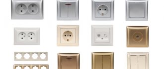
Types of devices for household use
There is no strict division into categories, since different manufacturers have their own “branded” model ranges, but several types of switches can be distinguished, united by one characteristic.
The two most common types of modern switches are the single-key wall-mounted model and the control panel, which is usually supplied with the lighting fixture.
For example, according to the principle of inclusion, all devices can be divided into:
- mechanical - elementary keyboard devices, easy to install and use (the function of a key can be performed by a lever, toggle switch, button, cord, rotary knob);
- electronic sensors activated by the touch of a hand;
- with remote control , equipped with a remote control or motion sensor.
The first group is considered the most popular, traditional and recognized from the first days of the invention of the electrical circuit; the popularity of the third is also gaining momentum, but the second somehow has not caught on.
Motion sensors save energy and serve as additional protection. For example, if you install such a device at the entrance to the house, it will signal the arrival of uninvited guests.
In residential premises, it is preferable to install internal models (with or without lighting), which do not protrude above the wall surface and look more aesthetically pleasing
According to the type of design, all switches are divided into single-key and multi-key (standard design for household use - with 2-3 keys). Each key serves to close/open one lighting circuit.
If there are several lighting fixtures in the room - a chandelier, ceiling lighting and sconces - a three-key switch is appropriate, which will allow you to turn on/off the devices alternately or together.
Also quite popular are two-key switches, which can be seen in almost every apartment. They are especially relevant for chandeliers with several lamps.
Based on the installation method, two groups can be distinguished: with external and internal installation. The external type is usually used when the wiring is exposed, and the internal type is used with cables sewn into the wall. To ensure the safety and stability of the installation of the built-in switch, use a mounting box (socket box) - a protective plastic case.
Based on the installation method, switches are divided into built-in and surface-mounted. The former are used for closed wiring, the latter for open wiring. Both options are installed according to similar schemes
Options for using backlights
As an example, let's look at options for using backlights in Legrand products.
The backlight mode in the illustration is indicated by a picture of the month, the installation of a switch with an operation indication is indicated by a picture of a light bulb.
A single-key switch with night illumination is connected according to the classical scheme: a light bulb on contacts L. To indicate operation, a working zero must be set to the backlight lamp.
Connecting a two-key switch is done in the same way. Each operating line has a separate indicator light. The circuit provides separate indication of the double switch, each backlight works for its own line.
The three-key switch works exactly the same way. There will only be three indicators. By the way, this is another argument for opponents of the backlight: a three-key switch in display mode spends 3 times more energy than a double switch.
The pass-through switch can also work with backlight. Only the switching diagram will be different. The indicator is connected to those contacts that will be open when the key is in the “down” position. As a result, if you turn on the light with one of the “pass-throughs”, the backlight on it goes out.
When using the backlight as an indication of lamp operation, the indicator is connected to the lamp side, and a separate working zero is connected to it. Regardless of the position of the “feeders”, when the lighting is turned on, the indicator will light up.
Legrand sells backlight lamps separately. In essence, it is an ordinary LED with a quenching resistor and a freewheeling diode, packaged in a heat-shrinkable tube.
If you don’t want to overpay for the logo on the price tag, you can make a spare indicator yourself. The circuit is simple: in order to prevent reverse current from flowing through the LED element (we have alternating voltage in the network, the polarity changes with a frequency of 50 Hz), a reverse diode (type D226) is installed. And since the voltage drop across the LED is 2–3 volts (depending on the color), a current-limiting resistor is installed in the circuit. Diagram and part values in the illustration:
Any switch can be equipped with such an indicator, the main thing is that the light breaks through the plastic.
We’ve figured out how to install a backlit switch, now we’ll deal with stray light. Cunning craftsmen are already offering for sale certain modules that are connected in parallel with housekeepers and LED lamps.
In fact, these are ordinary load resistors. They actually block unwanted light while using as much energy as a low-wattage incandescent lamp. That is, your lights are turned off, but the meter continues to wind.
To “make friends” between a backlit switch and LED (economical) lamps, you need a pass-through switch.
You connect a working lamp to one output, and an indicator with a separate working zero to the second. In this case, the phase works only for one consumer: either the main lamp or the indicator. In principle, there can be no parasitic glow.
Yes, the connection circuit is more complicated (you will have to draw the neutral wire). But you have to pay for the comfort of use. Electricity consumption is minimal, power no more than 1 watt.
Device
Connecting an illuminated switch is a simple procedure, but it’s worth knowing how to choose a high-quality model or how to remake what you already have. The light in the switch is usually a series connection of an LED/neon lamp with a resistor. This small circuit is connected in parallel with the switch contact. It turns out that regardless of whether the light is on or off, this circuit is always energized.
With this connection, when the lighting is turned off, the following circuit is created: the phase goes through a current-limiting resistor, flows through an LED or neon lamp, through the connection terminals it goes to the light bulb, through the incandescent filament to the neutral. That is, the backlight is on.
When the switch is on, the backlight circuit is shunted by a closed contact, the resistance of which is much lower. There is almost no current flowing through the backlight, it does not burn (it can burn at a third or a quarter of the “incandescence”).
The principle of operation of the backlight in the switch
As already mentioned, a current-limiting resistor (resistance) is installed in series with the LED or neon lamp in the switch. Its task is to reduce the current to an acceptable value. Since LEDs and neon lamps require different amounts of current, resistors are set to different values:
- for neon 0.5-1 MOhm and power dissipation 0.25 W:
- for LEDs - 100-150 kOhm, power dissipation - 1 W.
But connecting the LED backlight only through a resistor is not the best option. Firstly, the resistor gets very hot. Secondly, with such a connection, there is a possibility that reverse current may flow through the circuit. This may lead to breakdown of the LED. Thirdly, in models with LED backlighting, the electricity consumption of one switch can exceed 300 W per month. It seems like a little, but if there is backlighting on every key of every switch... There are more economical and safer schemes for backlit switch keys.
With diode
First of all, it is worth solving the problem of reverse current. The reverse current threatens to breakdown the LED, that is, the backlight will not work. This problem can be solved very simply - by installing a diode in parallel with the LED element.
Illumination option in electrical switch
With this scheme, the power dissipation of the resistor is at least 1 W, resistance 100-150 kOhm. The diode is selected with parameters similar to those of the LED. For example, KD521 or analogues are suitable for AL307. The disadvantage of the circuit is still the same: the resistor heats up and the backlight “pulls” a lot of energy.
Please note that this type of illuminated switch will work fine with incandescent bulbs. It may not work correctly with LED chandeliers or housekeepers.
With capacitor: to save energy
To solve the problem of a heating resistor and reduce backlight costs, a capacitor is added to the circuit. The parameters of the resistor are also changed, since now it limits the charge of the capacitor. The diagram looks like this.
Illumination circuit for switch keys with a capacitor
Resistor parameters - 100-500 ohms, capacitor parameters - 1 mF, 300 V. Resistor parameters are selected experimentally. Also, in this circuit, instead of a regular diode, you can install a second LED element. For example, on the second key or on the opposite side of the case.
Such a circuit practically does not draw electricity. Monthly consumption is about 50 W. But placing a capacitor in a small space in the case is sometimes problematic. And working with LED and energy-saving lamps is still not guaranteed.
How to connect illuminated switches
Let’s say right away that connecting a switch with backlight is exactly the same as for models without it. The circuits are no different, since the presence of additional backlight circuits does not affect the functions. According to safety precautions, a phase is connected to the switch - this is done so that when the switch is turned off, there is no voltage on the socket contacts. Neutral (zero) and ground go directly to the lamp or chandelier. And be careful: we only work with the voltage turned off. If possible, create a visible gap - remove the fuse or unscrew the plugs. Put a sign on the machine so that when you are digging through the wiring, no one turns on the power.
Where to connect the wires
If you are holding a switch in your hands for the first time, you will have many questions. Before you start connecting and installing, you need to understand the design. To do this, you need to disassemble it, consider what and why. In most cases, to disassemble the switch, you need to remove the keys. This applies to the famous Legrand, and simpler manufacturers like Viko, and all sorts of others.
The keys on the switch are held on by plastic latches or pins. Usually it is enough to grab the key, pull it towards you and down a little. You can try prying it off with a flat screwdriver. Just don't put in too much effort. As soon as you remove one key, the rest will “go” without problems.
Removing the keys and frame
Next, you still need to remove the decorative frame of the case. It is held on by a couple of screws, finding and unscrewing them is not a problem. Now we get to the electrical part. If you look carefully, you can find terminals for connecting wires. In most cases these are copper pads with screws. They are easy to identify. If your switch has these, when connecting, you need to strip the wire of insulation, insert it under the screw and contact plate, and tighten the screw. You need to tighten it with enough force, but do not overdo it. It’s better to tighten the screws again after half an hour - the copper will give a little under the screw, and you need to create a reliable connection. So check the connection again and tighten it a little.
Connection diagram for a switch in a distribution box
Look in the figure at the light control circuit using pass-through and cross switches. It is carried out as follows: Install changeover switching structures in the required places. Take out three-core cables from them. Mount an electric lamp, or several, connected in parallel connection. Take out a two-core cable from them. Install a junction box.
The scheme is simple, and you don’t need any special skills or knowledge to create it. If the switch disconnects from the load not the phase, but the neutral wire, then the wiring will always remain energized, which is not only inconvenient, but also dangerous. Russian Federation domikelectrica.
For any, up to V. Features of cross-type switches: For their connection, exclusively four-wire wires are used. The design of a simple switch with one key: 1 - a key with which the mechanism is activated; 2 — decorative frame; 3 - the working part, which contains the electrical mechanism. Switches are installed in all rooms where there are any lighting devices that are not equipped with a power cable, for example, it is not needed for floor lamps or table lamps.
If such a device is not available, it can be made from a two-key pass-through device. The open or closed method of cable installation does not fundamentally affect the arrangement of circuit elements. And this device switches them crosswise with each keystroke.
Ways to get rid of “blinking” lamps
Everyone loves backlit switches - beautiful, convenient, inexpensive, practical. But they are ideally compatible only with incandescent lamps - conventional or halogen. It’s generally better not to use them with housekeepers - they blink constantly. Can work with high-quality dimmable LEDs. But only high quality ones. Read - dear. And then, over time, if there is a low-quality transformer somewhere, problems may begin. This means that either the lamps will shine at full intensity, or they will “burn out” when turned off. So, connecting an illuminated switch is only possible with “old” lamps?
Convenient - no need to look on the wall
There is a solution to the problem, and even several. Varying degrees of difficulty. Moreover, not all of them work and do not always work. So you can try them one by one. Here's how to make friends with an illuminated switch and LED bulbs:
- Screw one incandescent lamp into a chandelier with LED or housekeepers. The power is selected experimentally.
- If the LEDs are “built-in” and there is no way to add an incandescent lamp without damaging the chandelier, a capacitor with a capacity of 0.22 μF, rated at 630 V, is installed parallel to the chandelier. The same solution is suitable for groups of built-in LED lamps. A capacitor is placed in front of the first lamp in the branch, parallel to it.
- The radical solution to the problem is to “bite out” the backlight circuit. This will not affect the functionality of the switch in any way. The second way is to pull out the neon lamp. This is easier if the circuit is integrated into the body, as is done in Legrand illuminated switches.
Just remove the highlight
All options except the last one have one drawback. Due to stray currents that flow through the backlight circuit, LED lamps are constantly energized. As long as the current is insufficient to start glowing, this is simply not noticeable. But the built-in voltage converters are “in operation” all the time. How this affects the lamps is not yet very clear, but there is an assumption that they will burn out faster.
Design
Cross switches (LeGrand, Schneider Electric and others) have not three contacts (like most standard control units), but four. This design allows you to simultaneously disconnect or enable two contacts. Thanks to this, several power lines (in this case, two) are simultaneously closed or, on the contrary, opened.
Photo - diagram of the operation of the cross switch
The main difference between pass-through switches and cross switches is that the former can be used independently, while the latter cannot. Cross models are used only in conjunction with pass-through models, but their designation on the diagrams is identical.
They are two paired single-key switches (sometimes single-key), the contacts of which are connected using special metal jumpers. The main convenience of this design is that, if necessary, you can make them yourself. This model has only one button, which is responsible for the operation of the contact system.
Photo - connection principle
There are two types of such switches based on the principle of operation:
- Keyboards;
- Rotary.
In rotary contacts, the contacts are closed using a rotary mechanism. They are slightly more expensive than regular ones, but have more diverse design options.
And two for installation options:
- Invoice (Unica Q, Lezard);
- Built-in (Legrad, ABB).
The external one is mounted on top of the wall. To install it, there is no need to break through the surface of the house and install an additional block in the wall. This is very convenient if you are planning a designer renovation or simply do not want to re-decorate the room. But such models are considered insufficiently convenient to use - they are subject to physical influences and the influence of an aggressive environment.
Photo - light control diagram from three places
Built-in ones are used for installation in walls. They are used for wiring in all types of buildings. To install them, you must first prepare a hole in the wall corresponding to the switch box.
Features of cross-type switches:
- To connect them, exclusively four-core wires are used. As a last resort, experts recommend using two two-core wires with good insulation, but such a solution is impractical;
- Such a switch can be one-key, two-key or three-key. But it is recommended to install it only if it is necessary to turn off the lights from three different places (say, at the beginning, middle and end of the corridor). In all other cases, you can use classic pass-through options;
- The intermediate switch is installed exclusively at the stage of wiring around the house or apartment. This is its main drawback. Due to the connection of several contact groups, connecting the system requires a large number of wires, which can create a certain fire hazard;
- Among the advantages of the design are high wear resistance. Considering that the contacts of crossover models are more likely to close than through-type or conventional ones, the jumpers are made of durable, corrosion-resistant metal, most often copper or alloy steel. Most options have additional protection against condensation, dust and moisture.
Photo - connecting a single-key cross switch