How to control a lamp from several places, and even using regular buttons instead of key switches? In order for this to work, you need to have a pulse (bistable) relay. Some sources call it pulsed, some bistable, so both names are appropriate - choose whichever you like.
Using a circuit consisting of a bistable relay plus any number of buttons (like a bell), you can control the lighting from any number of places. This is needed in long corridors, rooms where it is possible to enter the room from two sides, in bedrooms where the main light can be turned on both at the door and at the bed.
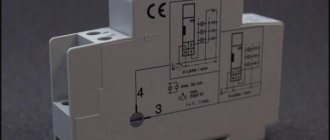
Block diagram of a bistable relay
The operating principle of a pulse relay is shown in the animated figure (look at it carefully):
- The phase potential (L) goes to both the button and the relay.
- When we use the button (S1) to apply potential to the relay, it closes the internal contact of the relay and supplies power to the lamp, even if the button (S1) is released.
- Subsequent application of potential to the relay using the button will turn off the lamp until the button is pressed again.
- Both the lamp and relay must be connected to the neutral (N) wire for everything to function as it should.
Electromagnetic or electronic
On numerous electrician forums, debates continue about which type of pulse relay is better, electronic or electromagnetic? Everyone gives their own arguments proving that the type of relay they have chosen is better than the other. Opponents present their own arguments for this. To understand this issue, you need to understand what characteristics are inherent in both types of relays.
- An electromechanical relay is not afraid of voltage surges and is insensitive to interference, but does not support synchronous control over one wire (modern models do not have this disadvantage).
- An electronic relay is afraid of voltage surges and is sensitive to interference, but supports synchronous control over one wire. In addition, the ladder machine included in many relays allows you to regulate the speed of their operation when a control signal is supplied.
Bistable impulse relay
Simple connection diagram
The simplest circuit has one button and a bistable relay located with this button. Such a system makes sense only when the relay can be controlled from another source, for example, using a remote control or a central control system (smart home element).
- Mains power 220V is connected to the terminal (L) of the button (S1).
- The electrical potential from terminal (L) is transferred directly to the relay terminal (1) (PB). The potential from this wire will be transferred to the lamp when the relay operates.
- We connect the neutral (N) and protective (PE) wires outside the button (P1). The protective wire (PE) is connected to the PE terminal in the lamp, and the neutral wire is connected to the N terminal of the lamp and to the terminal (A2) of the relay.
- When the button is used to indicate the potential at terminal (A1) of the relay, the relay connects terminals (1) and (2) together with the contact and the lamp turns on. After releasing the button, the contact will remain closed, so the lamp will remain on.
- The change will occur when the button is pressed again and the relay opens the contact, breaking the connection between terminals (1) and (2).
Device
There is a wide variety of pulse relays on the market; due to technical and design differences, you can find different devices. But as an example, we will consider the simplest and most practical principle of operation for understanding (see Figure 1).
Rice. 1. Example of a pulse relay device
The simplest example of a pulse relay consists of the following elements:
- Coil - made of a copper conductor wound on a non-magnetic base, for example, a frame made of textolite, electrical cardboard, etc. Designed to create an electromagnetic field that affects magnetic elements.
- The core is made of ferromagnetic materials that interact with the magnetic field of the coil. Designed to move and perform magnetic influence.
- Relay contact system - consists of movable and fixed contacts designed to transmit a signal.
- Resistive, capacitive and signal elements are used to set the operating logic of the device and indicate the state.
- Timer – sets the time interval for the relay, but is not present in all models; it helps to significantly expand the functionality of the equipment.
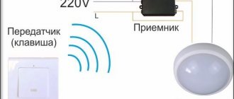
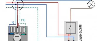
Relay control from two places
The electric potential from the phase wire (L) is transferred to terminal (2) of the button (S1), both when the button (S1) and (S2) are pressed. Inside in the diagram you can see the coil symbol which controls the relay contact when we apply voltage to terminals (A1) and (A2).
This way we can attach any number of buttons to control the light independently from different places. If you want to add an additional control from another location, simply add another button into the circuit and connect it in parallel to any other button that controls that lamp, or directly to a relay.
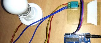
Model for motion sensor
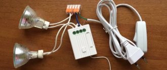
Motion sensor devices are very simple to make. In this case, modules can be used of the wave type with a conductivity of 4 μm. In this case, the rated voltage should be about 30 V. Transceivers for devices are selected using wire resistors. If we consider a circuit with dipole conductors, then an expander will be needed. It should also be noted that experts advise not to use conductor resistors with low sensitivity. They have a low conductivity threshold and quickly overheat. Capacitors for the relay are selected at 4 pF. This capacity is sufficient for rapid generation of pulses.
Bistable relay with two buttons
Now let's take a bistable relay, which can be installed outside the box, for example, in a home switching device. So here is another connection diagram for you to study.
This is essentially the same as in the previous figure, only the shape of the relay has changed.
Useful: Capacitive soil moisture sensor
Working in non-standard situations
Such situations, first of all, should include moments when the electricity in the apartment is completely turned off. When it is restored, the relays behave differently:
- For devices of an electromechanical system, removing the supply voltage does not lead to switching, therefore, when power supply appears, the lighting will be in the state in which they were caught when the power supply disappeared. If the light was turned on, it will turn on again, if it was turned off, it will remain turned off;
- electronic devices with non-volatile memory will behave in the same way;
- simple electronics without memory will reset the state to the position provided by the developers - usually to the off position (but sometimes to the on position).
Another possible collision is the simultaneous pressing of two buttons in different places. The system will perceive this as one click, regardless of the design of the relay, and will move the contact group to the opposite position.
We recommend viewing: Using relays to control lighting in the house.
The use of pulsed devices allows you to build convenient lighting control schemes that allow you to turn on the lights only when people are at the site. This provides significant savings on electricity. Also, such schemes make it possible to increase the comfort of operating utility networks. In many cases, their use is justified from an aesthetic point of view.
What does a pulse relay look like?
Here is the test system. The bell button will be installed in a box and connected to a bistable relay. On the right side of the relay there are 3 independent electrical connectors connecting the phase, neutral and protective wires. The power cord is currently connected to them.
- Control terminals (A1) and (A2).
- Terminals (2) and (1), to which we connect the power cord and the phase wire to the lamp.
- In the central part of the relay there is a black button that can be pressed manually without bell contact buttons connected by wires.
Varieties
A wide selection of pulse relays provides a fairly large assortment, differing in both pricing policy and functionality provided. According to the principle of operation, all models can be divided into electromechanical and electronic (Figure 4).
Figure 4. Electronic and electromechanical relay
The first option involves mechanical movement of the elements of the pulse device due to electromagnetic interaction between the coil and the core. The second type is controlled by semiconductor elements and switches without mechanically opening contacts and moving parts.
In addition, pulse relays may differ in:
- Rated load - indicates the permissible amperage that can be connected to the power contacts;
- Number of poles - can have a different number of inputs and outputs to implement certain tasks;
- Installation method - can be mounted on a DIN rail in accordance with section 1 of GOST R IEC 60715-2003, a bracket or other placement option;
- Purpose – the most popular are pulse relays for controlling lighting, protection and alarm circuits.
Also, bistable devices differ in overall dimensions, case materials, and the presence or absence of signal lamps.
Practical relay connection
Before starting work, be sure to turn off the voltage in the electrical circuit and use a tester to check the presence of 220 V potential on the wires with which we will work.
Connect the power cable (2) to the phase wire connector.
We will run a two-wire cable between the box and the relay. We will connect the brown wire to the connector so that we can press the external button.
The second wire is blue, it will have potential. Let's connect it to the control contact (A2) of the relay.
The next step is to connect the clamp (A1) to the neutral wire connector and also connect the wires to the lamp. The conductors and neutral protection are connected to the appropriate connectors, and the brown wire (phase) to the terminal (1) of the relay so that it operates by receiving the potential supplied to the terminal (2).
The button connection is classic. Connect the power cord to terminal (L) and to terminal (2) of the wire, with the help of which we will transmit short relay control pulses.
Then we attach another button to the circuit. To do this, we will run a two-wire cable between two boxes.
In the second, we can install a backlit bell button so that we can see changes in the potential on it. The connection method is similar. We connect the wires by color in the same way as in the first button.
Everything is ready - click and check the operation of the test system.
Main technical characteristics
When purchasing a device, you need to pay attention to the main parameters:
- contact group power;
- supply voltage;
- coil actuation current;
- design of the contact group (closing-opening or changeover);
- additional service functions.
You also need to pay attention to such a parameter (illogical at first glance) as the number of connected switches. It would seem that the characteristic is absurd, but we must take into account the widespread use of devices with backlight chains. If there are a lot of them, then the resulting total current through these circuits will be sufficient to trigger the relay.
The control voltage for most devices is 220 volts, but there are also relays with low-voltage control (12..36 volts). Such devices have a huge safety advantage, but require an additional power source. Therefore, such devices are not widely used in everyday life (as opposed to in production).
Through the control circuit, bistable switching devices consume very little current (this power consumption has virtually no effect on the electric meter readings). This fact makes it tempting to make control circuits with wires of reduced cross-section (up to 0.5 sq. mm). It should be remembered that to protect such conductors, it will be necessary to install a separate circuit breaker with a lower operating current in the switchboard. Feasibility is decided on a case-by-case basis.
Conclusions and useful video on the topic
The video material tells about the device, operation, application and history of the creation of this type of device:
The following story describes in detail the operating principle of solid-state or electronic relays:
The use of pulse relays is increasingly used in modern electrification systems. Increasing demands for functionality and flexibility in lighting control, material savings and safety create a continuous impetus for the improvement of contactors.
They are reduced in size, simplified in design, increasing reliability. And the use of fundamentally new technologies at the heart of the work allows them to be used in harsh conditions of dusty industries, vibration, magnetic fields and humidity.
References
To prepare the article, the following technical literature was used:
- Iglovsky I. G., Vladimirov G. V. “Handbook on low-current electrical relays” 1984
- Filipcheiko I, P., Rybin G. Ya. “Electromagnetic relays” 1968
- Gurevich V.I. "Electrical relays. Device, principle of operation and application. Engineer's Handbook" 2011
- Sivukhin D.V. “General course in physics” 1975
- Obolentsev Yu.B., Gindin E.L. “Electrical lighting of general industrial premises” 1990
Application
The scope of application covers all areas where automation requires remote control of one object from several points. In everyday life and some industries, this is room lighting that can be controlled from several points. This issue is especially relevant for organizing the power supply of a “smart home”.
In automation and centralization systems on the railway network, it provides telecontrol and dispatch signaling processes. Used for signaling and transmitting operating signals.
Why only push-button ones?
When using pulse relays, other types of switches are used - push-button, bell or push-type.
Please note that simple single-key or two-key keyboards will not work here.
With rare exceptions, for example for the Meander RIO-2 relay. But more on that later.
Based on this fact, a signal cannot be applied to pulse relays for too long, otherwise its coil will burn out. Some manufacturers warn that the continuous signal time on their models should be no more than 1 minute.
And some children really like to play with such buttons, after which they fail.
Push-button switches resemble ordinary ones in appearance, only inside their design there is a return spring, which after each press returns the key and contact to its original position.
There are also two-key buttons in one housing.
They will come in handy when you want to connect general lighting in the kitchen from one relay and at the same time illumination of the work area of the countertop.
Or in the hall - a chandelier and lighting around the perimeter, plus a separate sconce.
Many people use spring-loaded buttons for doorbells instead of special switches.
Tips and tricks
Before purchasing and installing a pulse relay, it would be useful to familiarize yourself with the most common errors that may arise at this stage. Experienced professionals who install switching systems of this type often advise adhering to the following recommendations:
- If you purchase an electronic pulse-type relay, it is better to give preference to models equipped with a timer. With this feature, you can set the power to automatically turn off after a certain period of time. This function will be very useful for organizing lighting on the street, as well as in rooms that are visited frequently, but not for long.
- If you plan to install backlit switches (buttons), you should check with the seller in advance whether the relay can work with such elements of electrical fittings. Many IRs are very sensitive to the appearance of even a small current in the electrical circuit, and the presence of a resistive element will lead to activation of the system. In addition, the device may deteriorate, because the coil will be constantly energized.
- During installation work, all parts through which electric current flows must be well insulated. For this purpose, you can use special heat-shrinkable tubes, as well as PVC insulating tape.
- If there is a small child in the house, then it is better to install the buttons to activate the relay higher. Such products are well insulated and practically safe during operation, but children often start playing with the buttons by holding them on for a long time. Such actions often lead to failure of electromechanical type pulse relays.
- Most models of pulse relays with a coil are designed for 220 V. Such products are very easy to connect to the electrical network, but if you need to ensure a high level of safety in wet rooms, you should choose 12 or 24 Volt models.
- If you need to install several pulse relays that will be used to turn off various lighting devices, then you should choose models with central control. Such a device can be forcibly turned off by applying electric current to one of its contacts. Therefore, if you connect several of these elements to one switch, you can turn off all the lights in the house with one press of a button.
- If there is no desire or opportunity to purchase new buttons to turn on the light using a pulse relay, then you can remake ordinary switches. For this purpose, it is necessary to install small springs under the keys so that after stopping pressing they return to their original position.
- When installing a large number of impulse switches, to save space, the buttons can be placed in one socket box.
A pulse relay is a very interesting product in its design and functionality, which can and should be used to organize more comfortable control of lighting devices. If a high-quality device is selected and the installation of the product is carried out without errors, then such a system will last for many years.