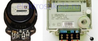
Analog multimeter
This type of multimeter displays measurement readings using a arrow, underneath which is a display with different scales of values.
Each scale shows the readings of one or another measurement, which are signed directly on the scoreboard. But for beginners, such a multimeter will not be the best choice, since it is quite difficult to understand all the symbols that are on the display. This may lead to misunderstanding of the measurement results.
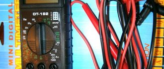
Digital multimeter
Unlike analogue ones, this multimeter allows you to easily determine the quantities of interest, while its measurement accuracy is much higher than that of pointer instruments.
In addition, the presence of a switch between different characteristics of electricity eliminates the possibility of confusing one value or another, since the user does not need to understand the gradation of the indication scale.
The measurement results are displayed on the display (in older models - LED, and in modern ones - liquid crystal). For this reason, the digital multimeter is user-friendly for professionals and simple and intuitive for beginners.
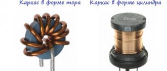
Inductor
it is an insulated wire wrapped repeatedly around a core.
Typically the frame is cylindrical or toroidal.
Inductance is considered the main characteristic of a coil. This quality expresses the ability of an element to convert alternating current into a magnetic field.
Important! Even a single wire is magnetic if the current flowing through it changes. The influence of the camp is directed in such a way as to counteract its change. If it increases, the field slows it down, and if it weakens, it strengthens it.
Inductors
Determining the direction of field lines obeys the “rule of thumb”: if the thumb of a hand clenched into a fist points in the direction of the change in the current force, the closed fingers indicate the direction of the field of force lines.
Consequently, if the wire is wound repeatedly on a cylindrical base, the lines of force of different turns add up and pass through the axis.
To increase the inductance, a ferromagnetic core is placed in the center of the cylinder.
Inductance meter for multimeter
Despite the fact that it is rarely necessary to determine inductance when working with electronics, sometimes it is still necessary and multimeters that measure inductance are difficult to find. In this situation, a special attachment for a multimeter will help, allowing you to measure inductance.
Often, for such a set-top box, a digital multimeter is used, which is configured to measure voltage with a measurement accuracy threshold of 200 mV, which can be purchased at any ready-made electrical and radio equipment store. This will allow you to create a simple digital multimeter attachment.
Measuring devices for a specific assessment of the value of the measured capacitance include microfaradmeters, the operation of which is based on the dependence of the current or voltage in the alternating current circuit on the value of the measured capacitance included in it. The capacitance value is determined by the comparator scale.
In a broader sense, symmetrical AC bridges are used to measure the characteristics of capacitors and inductors, allowing a small measurement error (up to 1%) to be obtained. The bridge is powered by generators operating at a fixed frequency of 400-1000 Hz; electric rectifiers or millivoltmeters, as well as oscilloscope indicators, are used as indicators.
This measure is achieved by balancing the bridge as a result of alternate adjustment of its two arms. Readings are taken from the limbs of the arms of those shoulders that serve to balance the bridge.
As an example, consider the measuring bridges that are the basis of the EZ-3 inductance (Fig. 1) and the E8-3 capacitance meter (Fig. 2).
With a weighbridge (Fig. 1), the inductance of the coil and its quality factor are determined by the formulas Lx = R1R2C2; Qx = wR1C1.
When balancing jumpers (Fig. 2), the measured capacitance and loss resistance are determined by the formulas
Measuring capacitance and inductance using the ammeter-voltmeter method
To measure small capacitances (less than 0.01 - 0.05 μF) and high-frequency inductors in the spectrum of their operating frequencies, resonant methods are widely used. The resonant circuit usually contains a high-frequency oscillator, inductively or via capacitance, connected to the LC measuring circuit. High-frequency sensitive devices that respond to current or voltage are used as resonance indicators.
The ammeter-voltmeter method is used to determine relatively large capacitances and inductances when the measuring circuit is powered from a low-frequency source of 50 - 1000 Hz. For measurements, you can use the diagrams in Fig.
According to instrument readings, impedance
where is it
from these expressions one can find
When active losses in a capacitor or inductor can be neglected, use the circuit in Fig. 4. In this case
Measuring the mutual inductance of 2 coils can be carried out using the ammeter-voltmeter method (Fig. 5) and the method of alternately connected coils.
When measuring using the second method, the inductance of 2 alternately connected coils is measured when the coils are turned on with a consonant LI and a counter LII. Mutual inductance is calculated using the formula
Inductance measurements can be performed using one of the methods described above.
Inductance check
The presence in the arsenal of a multimeter of such a useful function as measuring the inductance of the coils will be useful for checking the compliance of the inductor with the characteristics stated in the reference literature. This feature is only available on some digital multimeter models.
To use this feature, you must set your multimeter to measure inductance. The probe contacts are connected to the coil terminals. For the first measurement, the multimeter is set to its largest measurement range, and then the range is reduced to obtain a measurement of sufficient accuracy.
When carrying out all measurements, it is important not to allow your hands to touch the contacts on which certain parameters are measured, otherwise the conductivity of the human body may change the readings of the device.
Set-top box assembly
You can assemble a tester connecting to a multimeter to measure inductance without problems at home if you have basic knowledge and skills in the field of radio engineering and soldering of microcircuits.
In the circuit, you can use transistors KT361B, KT361G and KT3701 with any letter designations, but for more accurate measurements it is better to use transistors marked KT362B and KT363.
These transistors are installed on the board in positions VT1 and VT2. In position VT3 it is necessary to install a silicon transistor with a pnp structure, for example, KT209V with any letter marking. Positions VT4 and VT5 are for buffer amplifiers.
Most high-frequency transistors are suitable, with h21E parameters for one not lower than 150, and for the other higher than 50.
Any high frequency silicon diode will be suitable for positions VD and VD2.
The resistor can be chosen MLT 0.125 or similar. Capacitor C1 is taken with a nominal capacity of 25330 pF, since it is responsible for the measurement accuracy, and its value should be selected with a deviation of no more than 1%.
Such a capacitor can be made by combining thermally stable capacitors of different capacitances (for example, from 2 to 10,000 pF, from 1 to 5100 pF and from 1 to 220 pF). For other locations, any small-sized electrolytic and ceramic capacitors with an acceptable spread of 1.5-2 times are suitable.
The contact wires to the board (position X1) can be soldered or connected using spring clamps for "speaker" wires. Connector X3 is intended for connecting the set-top box to a multimeter (frequency meter).
It is best to use shorter wire for bananas and alligators to reduce the effect of inductance on the measurement readings. In the place where the wires are soldered to the board, the connection must be additionally secured with a drop of hot glue.
If you need to adjust the measuring range, you can add a switch connector (eg three ranges) to the card.
Required Parts
This is a tester that has a magnetoelectric mechanism to measure current, so it only measures DC current. The moving coil with an arrow is mounted on guy wires. Used in analog electrical measuring instruments.
Finding it at a flea market or buying it at a radio parts store won’t be a problem. There you can also purchase other materials and components, as well as attachments for the multimeter. In addition to the microammeter you will need:
a dozen fixed resistors;- one variable resistor;
- female connector for 12-16 pins;
- a piece of one-sided fiberglass;
- a couple of meters of copper stranded wire with a cross section of 1 square. mm;
- 40 cm of single-core copper wire with a cross section of 4 square meters. mm;
- solder, rosin, 60 W soldering iron.
If a person decides to make himself a multimeter with his own hands, it means that he has no other measuring instruments. Based on this, we will continue to act.
Multimeter attachment housing
The body can be made from a ready-made box of a suitable size, or you can make the box yourself. You can choose any material, such as plastic or thin fiberglass. The box is adapted to the size of the table and has holes for mounting. There are also holes for connecting wiring. Everything is fixed with screws.
The set-top box is powered from the mains via a 12 V power supply.
Tools we will need
Many of the tools may already be available to DIY radio enthusiasts. Otherwise, you will have to purchase them or make them yourself from scrap materials.
Therefore, before unsoldering the radio component, get the following devices:
- A soldering iron of the required power and design for heating the contacts of radio components . You can take a ready-made one, or you can make it yourself; the manufacturing process is described in detail in the following article:
- Tweezers or clamp - used for manipulating radio components. Allows you to hold elements with tweezers, fix their position and provide additional heat removal when you try to desolder them.
- Tubular-shaped needles are sold ready-made, but if you don’t have any on hand, they can be replaced with a regular medical syringe needle, the main thing is that the inner diameter fits onto the stem of the radio component. In addition to needles, you can use tubes or sleeves; with their help, heated radio components are separated from the solder.
Rice. 1. Set of soldering needles
- Dismantling braid also acts as an auxiliary tool if you need to desolder those elements that have a large number of legs on the printed circuit board. You can either purchase a ready-made one or make it yourself.
Rice. 2: dismantling braid
- A desoldering pump is a device for removing solder from a mounting location, allowing you to quickly desolder a large number of radio components. Structurally, it includes a vacuum flask, a return spring and a piston driven by it. In addition to purchasing a factory model, you can make a desoldering pump yourself.
Rice.
3. Desoldering pump Inexperienced electricians may argue that so many tools for desoldering radio components will be too many. After all, soldering is performed using a regular soldering iron, but all of the above devices will help you solder the necessary elements quickly and accurately. This is especially true with large volumes of contact pins in the board. Now let's look at the practical application of each of the tools described above.
What is called inductive reactance
When an alternating voltage is applied to a coil, the current flowing through it changes according to the applied voltage. This causes a change in the magnetic field, which creates an electromotive force that prevents this from happening.
Measuring circuit
In such a circuit, there is a dependence of the electrical parameters of two types - conditional and inductive. They are designated R and XL respectively.
Under normal conditions, the power supply is assigned. However, on reactive elements it is zero. This is due to the constant reversal of the direction of alternating current.
During the oscillation period, energy is pumped into the coil twice and returned to the source the same number of times.
Definition of inductance
Series and parallel connection of inductors
Inductors can be connected in series or in parallel, resulting in a set with new characteristics.
Parallel connection
When the coils are connected in parallel, the voltages on all elements are equal, and the currents (variables) are distributed in inverse proportion to the inductances of the elements.
- U=U1=U2=U3;
- I=I1+I2+I3.
The total inductance of the circuit is defined as 1/L=1/L1+1/L2+1/L3. The formula is valid for any number of elements, and for two coils it is simplified to the form L=L1*L2/(L1+L2). Obviously, the final inductance is less than the inductance of the element with the smallest value
Serial connection
With this type of connection, the same current flows through a circuit made up of coils, and the voltage (alternating!) on each component of the circuit is distributed in proportion to the inductance of each element:
- U=U1+U2+U3;
- I=I1=I2=I3.
The total inductance is equal to the sum of all inductances, and will be greater than the inductance of the element with the largest value. Therefore, such a connection is used when it is necessary to increase the inductance.
Important! When connecting coils into a series or parallel battery, the calculation formulas are correct only for cases where the mutual influence of the magnetic fields of the elements on each other is excluded (by shielding, large distances, etc.). If an influence exists, then the overall value of the inductance will depend on the relative position of the coils.
Setting up an inductance meter
To calibrate the inductor tip, several inductive coils with known inductances (for example, 100 µH and 15 µH) are required.
The coils are connected in turn to the attachment, and, depending on the inductance, the trimmer resistor slider on the multimeter screen sets the value to 100.0 for a 100 µH coil and 15 for a 15 µH coil with an accuracy of 5%.
In the same way, the device is adjusted to other ranges. An important factor is that accurate test inductance values are required to accurately calibrate the tip.
An alternative method for determining inductance is the LIMP program. But this method requires some preparation and understanding of the program.
But in both the first and second cases, the accuracy of such inductance measurements will not be very high. This inductance meter is not very suitable for working with high-precision equipment, but for home use or radio amateurs it will be an excellent assistant.
How to check a fluorescent lamp starter
The process of checking fluorescent lighting devices involves not only checking the integrity of the spiral inside the light bulb, but also the operation of the acceleration and starting systems.
- capacitors that should not swell, deform or explode when exposed to excessive voltage in the electrical network;
- a light source bulb that cannot be dimmed.
The integrity of the capacitor is checked with a multimeter in ohmmeter mode with the maximum possible resistance measurement range.
If the tester reading is less than 2.0 MΩ, it can be assumed that the capacitor has unacceptable leakage current. As practice shows, the best option when carrying out independent repair work would be to completely replace all worn-out elements (starter and throttle valve) with new devices of a similar type.
Checking in lamps
The throttle must be checked if one of the above-described phenomena is observed when the fluorescent lamp is operating, as well as if a characteristic smell of burning insulation is noticed, sounds that are not typical for the operation of the device are observed, and also if the lamp does not turn on.
Before checking the lamp choke, the lamp itself and the starter are checked.
A malfunction of the inductor may consist of a break or burnout of the coil wire or an interturn short circuit caused by breakdown or burning of the insulation.
Both malfunctions can occur either due to a long period of use of the device, or as a result of any mechanical impact. It is possible for the coil wire to burn out as a result of supplying it with a current greater than the maximum for which the inductor is designed.
In the event of a wire break or burnout, you can identify the fault with a conventional tester or multimeter. Due to the fact that the inductor passes direct current, closing the tester circuit through the coil, you can understand by the glow of the control lamp or its absence whether there is a break or not.
If, when measured with a multimeter, the resistance is infinite, the coil wire has broken.
Typical examples of using an LCR meter and a transistor tester for checking radio components
Resistors are the most common type of radio components
Wirewound resistors with different power ratings
| If there are no problems with common values, measuring low resistance resistors can complicate the task. With a conventional multimeter you can often measure normal resistance of the order of 1-2 ohms and higher; if lower, then the resistance of the wires, probes and low resolution begin to have a strong effect. Even the fairly accurate UNI-T UT61E has a measurement resolution in this mode of only 10 mOhm, while even an inexpensive LCR meter has a minimum resolution of 0.1 mOhm. | Digital multimeter UNI-T UT61E high accuracy with the ability to connect to a PC to delete logs |
Accordingly, if using a multimeter it is possible to relatively accurately measure resistors with a resistance of 0.05-0.1 Ohm, then when measuring 10 mOhm, practically nothing can be measured; for comparison, below is the measurement of two resistors with a nominal value of 1 and 2.2 mOhm.
Difference between multimeter and RLC tester readings when measuring low resistance resistors
Low resistance measurements are often required when testing, sizing or manufacturing current sensing shunts. An alternative option for measuring voltage drop, but requires an adjustable power supply, ammeter, voltmeter.
The current shunt is a low resistance resistor which is a low resistance resistor
The ability to measure low resistance is also useful for detecting problems such as marking errors, especially low resistance resistors.
The resistor on the left is labeled as 0.1 ohm, on the right as 0.22 ohm, but in reality they have almost the same resistance. Such mistakes can sometimes be very costly.
Before installing or soldering a resistor in a circuit, check its resistance. Make sure the nominal and actual values of the resistor are the same
Transistors
Measuring low resistances will help evaluate the originality of field-effect transistors. Currently, more and more counterfeit transistors and transistors with altered markings are appearing on the market. While simply measuring resistance doesn't give you the full picture, it does give you a quick idea of what's in front of you.
For the test, in addition to the device, a 9-volt battery is sufficient. Datasheets often refer to a gate voltage of 10 volts, but this is not relevant in this case. In addition, it is correct to measure the drain-source resistance by current; it is usually indicated in the documentation, but for this you need at least a laboratory power supply.
To test the transistor: we connect test probes to the drain and source terminals (usually the center and right), and apply 9 volts to the outer terminals. A constant voltage application is not required, just charging the gate capacitor is enough, but you need to be careful not to accidentally connect the battery to the tester probes. You can also “load” the transistor first, and only then connect the probes.
Capacitors
Capacitors are used somewhat less frequently, but have their own characteristics. For example, unlike resistors, they are much more susceptible to aging, especially when it comes to electrolytic capacitors installed in switching power supplies, motherboard converters, etc.
The ESR of capacitors is of particular importance. When a capacitor dries with almost no loss of capacity, its internal resistance increases significantly.
This cannot be diagnosed with a regular multimeter; you can change everything, but this is not always convenient, often difficult or expensive. Additionally, RLC meters often allow measurements to be made without desoldering the component, although this of course depends on the wiring diagram.
- Most multimeters measure the capacitor as ideal, that is, without taking into account its features, sometimes this is enough, sometimes not.
- More sophisticated devices can separate the capacitor from its internal resistance and measure these parameters separately.
- The equivalent circuit of a capacitor looks much more complex - all these parameters can be measured, but this is a completely different class of devices that ordinary radio amateurs usually do not need.
Equivalent series circuit, where R is the electrical resistance of the capacitor insulation, responsible for the leakage current, and the equivalent series resistance; L—equivalent series inductance; - capacitor capacity
For example, a comparison of two capacitors, cheap and branded Chinese. Although accurate, a conventional multimeter considers them almost identical, showing only a slight difference in capacitance. But if you connect the capacitors to an LCR meter, you can see that the difference in their internal resistance is almost 5 times! If you plan to use capacitors when switching power supplies, it is this resistance difference that will affect heating and, as a result, the service life and characteristics of the power supply. Capacitors with high internal resistance cannot effectively suppress peaks.
Chokes and inductors
Reactors, transformers, and winding units in general, unlike capacitors and resistors, are even more difficult to control, and typically a multimeter can measure inductance.
The main characteristic of the narrowing is inductance, that is, a coefficient that determines the dependence of the rate of change of electric current on the voltage on the coil
An impedance meter facilitates the manufacture of winding units, as well as the search for short circuits between turns. Compared to a good component or a component of known rating, you can tell that the transformer or inductance is faulty because its inductance will change greatly.
Electrical monitoring of inductors includes detection of turn short circuits (short circuits between winding turns). If there is an interturn circuit in the studio winding, its inductance will drop sharply.
Typically, there are indicators to detect shorted loops, but an impedance meter will also detect this problem. For example, on the left there is a working transformer, on the right it is the same, but with a shorted turn. It can be seen that the winding inductance has become significantly smaller, and the turn also affected the result of measuring the active resistance of the winding.
Comparison of the inductance of a working transformer and a closed-loop transformer
Alive or dead? Checking radio components
Many of us have often had to deal with the fact that because of one failed part, the whole device stops working. To avoid misunderstandings, you should be able to quickly and correctly check details. This is what I am going to teach you. First, we need a multimeter
Bipolar transistors
Most often, transistors burn out in circuits. At least for me. It is very easy to check their functionality. To begin with, it is worth ringing the Base-Emitter and Base-Collector transitions. They must conduct current in one direction, but not allow it to flow in the opposite direction. Depending on whether the PNP is a transistor or an NPN, they will conduct current to the Base or from the Base. For convenience, we can imagine it in the form of two diodes
It is also worth ringing the Emitter-Collector transition. More precisely, these are 2 transitions. . . Well, other than that, that’s not the point. In any transistor, no current should pass through them in any direction while the transistor is off. If voltage is applied to the Base, then the current flowing through the Base-Emitter junction will open the transistor, and the resistance of the Emitter-Collector junction will sharply drop, almost to zero. Please note that the voltage drop across the transistor transitions is usually not lower than 0.6V. And prefabricated transistors (Darlingtons) have more than 1.2V. Therefore, some “Chinese” multimeters with a 1.5V battery simply cannot open them. Don’t be lazy/stingy to get yourself a multimeter with “Krona”!
Please note that some modern transistors have a diode built in parallel with the Collector-Emitter circuit. So it’s worth studying the datasheet for your transistor if the Collector-Emitter rings in one direction!
If at least one of the statements is not confirmed, then the transistor is not working. But before you replace it, check the remaining parts. Perhaps they are the reason!
Unipolar (field-effect) transistors
A working field-effect transistor should have infinite resistance between all its terminals. Moreover, the device should show infinite resistance regardless of the applied test voltage. It should be noted that there are some exceptions.
If, during testing, you apply the positive probe of the test device to the gate of an n-type transistor, and the negative probe to the source, the gate capacitance will charge and the transistor will open. When measuring the resistance between drain and source, the device will show some resistance. Inexperienced repairmen may mistake this behavior of the transistor for its malfunction. Therefore, before “testing” the drain-source channel, short-circuit all the legs of the transistor to discharge the gate capacitance. After this, the drain-source resistance should become infinite. Otherwise, the transistor is considered faulty.
Please also note that in modern high-power field-effect transistors there is a built-in diode between the drain and source, so the drain-source channel behaves like a regular diode when tested. In order to avoid annoying mistakes, remember the presence of such a diode and do not mistake it for a transistor malfunction. You can easily check this by scrolling through the datasheet for your copy.
Capacitors
Capacitors are another type of radio components. They also fail quite often. Electrolytic ones die most often; films and ceramics deteriorate somewhat less frequently. . .
To begin with, the boards should be examined visually. Typically, dead electrolytes swell and many even explode. Take a closer look! Ceramic capacitors do not inflate, but they can explode, which is also noticeable! They, like electrolytes, need to be called. They should not conduct current.
Before starting an electronic test of a capacitor, it is necessary to perform a mechanical check of the integrity of the internal contact of its terminals.
To do this, it is enough to bend the leads of the capacitor one by one at a slight angle, and carefully turning them in different directions, as well as slightly pulling towards yourself, to make sure that they are motionless. If at least one terminal of the capacitor rotates freely around its axis, or is freely removed from the housing, then such a capacitor is considered unsuitable and is not subject to further testing.
Another interesting fact is the charge/discharge of capacitors. This can be seen if you measure the resistance of capacitors with a capacity of more than 10 µF. It is also present in smaller containers, but it is not so noticeably expressed! As soon as we connect the probes, the resistance will be a few ohms, but within a second it will increase to infinity! If we swap the probes, the effect will repeat.
Accordingly, if a capacitor conducts current or does not charge, then it has already passed into another world.
Resistors
Resistors are the most common on boards, although they do not fail very often. It’s easy to check them, just make one measurement - check the resistance.
If it is less than infinity and not equal to zero, then the resistor is most likely suitable for use. Usually, dead resistors are black - overheated! But black ones can also be alive, although they should also be replaced. After heating, their resistance could change from the nominal one, which would have a bad effect on the operation of the device! In general, it is worth ringing all the resistors, and if their resistance differs from the nominal value, then it is better to replace it. Please note that ±5% deviation from nominal is considered acceptable. . .
Diodes
In my opinion, it is easiest to check diodes. We measured the resistance, with a plus at the anode, it should show several tens/hundreds of ohms. We measured it with a plus on the cathode - infinity. If not, then the diode should be replaced. . .
Inductance
Rarely, but still, inductors fail. There are two reasons for this. The first is a short circuit of turns, and the second is an open circuit. It is easy to calculate a break - just check the resistance of the coil. If it is less than infinity, then everything is OK. The resistance of inductors is usually no more than hundreds of ohms. Most often several dozen. . .
The short circuit between turns is somewhat more difficult to calculate. It is necessary to check the self-induction voltage. This only works on chokes/transformers with windings of at least 1000 turns. It is necessary to apply a low-voltage impulse to the winding, and then short-circuit this winding with a gas-discharge light bulb. In fact, loving IN. The pulse is usually applied by lightly touching the CROWN contacts. If the IN eventually blinks, then everything is fine. If not, then there is either a short circuit in the turns or very few turns. . .
As you can see, the method is not very accurate and not very convenient. So first check all the details, and only then sin on the short circuit of the turns!
Optocouplers
The optocoupler actually consists of two devices, so it is a little more difficult to test. First, you need to ring the emitting diode. It should, like a regular diode, ring in one direction and serve as a dielectric in the other. Then you need to apply power to the emitting diode and measure the resistance of the photodetector. This can be a diode, transistor, thyristor or triac, depending on the type of optocoupler. Its resistance should be close to zero.
Then we remove the power from the emitting diode. If the resistance of the photodetector has increased to infinity, then the optocoupler is intact. If something is wrong, then it should be replaced!
Thyristors
Another important key element is the thyristor. He also likes to get out of order. Thyristors can also be symmetrical. They're called triacs! It's easy to check both.
We take an ohmmeter, connect the positive probe to the anode, and the negative probe to the cathode. The resistance is infinity. Then we connect the control electrode (CE) to the anode. The resistance drops to about a hundred ohms. Then we disconnect the UE from the anode. In theory, the thyristor resistance should remain low - the holding current.
But keep in mind that some “Chinese” multimeters can produce too little current, so if the thyristor is closed, it’s okay! If it is still open, then remove the probe from the cathode, and after a couple of seconds attach it back. Now the thyristor/triac should definitely close. Resistance is infinity!
If some theses do not coincide with reality, then your thyristor/triac is not working.
Zener diodes
A zener diode is actually a type of diode. This is why it is checked in the same way. Note that the voltage drop across the zener diode, with a plus at the cathode, is equal to its stabilization voltage - it conducts in the opposite direction, but with a larger drop. To check this, we take a power supply, a zener diode and a 300...500 Ohm resistor. We turn them on as in the picture below and measure the voltage on the zener diode.
We gradually increase the voltage of the power supply, and at some point, the voltage on the zener diode stops increasing. We have reached its voltage stabilization. If this does not happen, then either the zener diode is not working, or the voltage needs to be increased further. If you know its stabilization voltage, then add 3 volts to it and apply it. Then increase it and if the zener diode does not begin to stabilize, then you can be sure that it is faulty!
Stabilizers
Stabilizers are one of the types of zener diodes. Their only difference is that when connected directly - with a plus on the anode, the voltage drop across the stabistor is equal to its stabilization voltage, and in the other direction, with a plus on the cathode, they do not conduct current at all. This is achieved by connecting several diode crystals in series.
Please note that a multimeter with a supply voltage of 1.5V will not physically be able to set the stabilist to, say, 1.9V. Therefore, we turn on our stabistor as in the picture below and measure the voltage on it. You need to apply a voltage of about 5V. Take a resistor with a resistance of 200...500 Ohms. We increase the voltage by measuring the voltage on the stabistor.
If at some point it stopped growing, or began to grow very slowly, then this is its stabilization voltage. He is a worker! If it conducts current in both directions, or has an extremely low voltage drop in direct connection, then it is worth replacing. Apparently it burned down!
Cable/connector
Checking various types of cables, adapters, connectors, etc. is quite simple. To do this you need to call your contacts. In a loop, each contact must communicate with one contact on the other side. If the contact does not ring with any other contact, then there is a break in the loop. If it rings with several, then most likely there is a short circuit. The same goes for adapters and connectors. Those with a break or short circuit are considered defective and cannot be used!
Microcircuits/ICs
There are a great variety of them, they have many pins and perform different functions. Therefore, checking the microcircuit must take into account its functional purpose. It is quite difficult to accurately verify the integrity of the microcircuits. Inside, each represents tens to hundreds of transistors, diodes, resistors, etc. There are hybrids in which there are more than 200,000,000 transistors alone.
One thing is for sure - if you see external damage to the case, spots from overheating, cavities and cracks on the case, loose leads, then the microcircuit should be replaced - it is most likely damaged in the crystal. A heating microcircuit, the purpose of which does not involve heating it, must also be replaced.
A complete check of the microcircuits can only be carried out in a device where it is connected as it should be. This device can be either equipment being repaired or a special test board. When checking microcircuits, the typical inclusion data available in the specification for a specific microcircuit is used.
Well, that's it, no more fluff for you, and less burnt parts!
Tags:
- Multimeter
Carrying out inductance measurements
After assembly, you need to check the connection of the multimeter. There are several ways to control the device:
- Determination of the inductance of the measuring connection. To do this, you need to short-circuit two wires intended for connection to the inductive coil. For example, if the length of each wire and jumper is 3 cm, one turn of the induction coil is formed. This coil has an inductance of 0.1 - 0.2 μH. When determining inductance more than 5 μH, this error is not taken into account in the calculations. In the range of 0.5 - 5 µH, when measuring, it is necessary to take into account the inductance of the device. Readings below 0.5 µH are approximate.
- Measuring an unknown inductance value. Knowing the frequency of the coil, using a simplified formula for calculating inductance, you can determine this value.
- If the response threshold of silicon pn junctions is higher than the amplitude of the measured electrical circuit (from 70 to 80 mV), you can measure the inductance of the coils directly in the circuit itself (after it has been de-energized). Since the capacitance of the set-top box (25330 pF) is of great importance, the error of such measurements will not be more than 5%, provided that the capacitance of the measured circuit does not exceed 1200 pF.
When connecting the set-top box directly to the coils located on the board, 30 cm long wiring with clamps for fixation or probes is used. The threads are twisted at the rate of one turn per centimeter of length. In this case, the attack inductance is formed in the range of 0.5 - 0.6 μH, which also must be taken into account when measuring inductance.
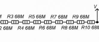
Determining the exact battery voltage
In order to find out the actual battery voltage yourself, you will need at least one accurate resistor with a nominal value of 2 or 2.2 kOhm with an error of 0.5%. This resistor value was chosen due to the fact that when a microammeter is connected in series with it, the total resistance of the circuit will be 5000 Ohms. Consequently, the current passing through the tester will be about 300 μA, and the needle will deflect to full scale.
I=U/R=1.5/(3000+2000)=0.0003 A.
If the tester shows, for example, 290 µA, then the battery voltage is
U=I*R=0.00029(3000+2000)=1.45 V.
Now knowing the exact voltage on the batteries, having one exact resistance and a microammeter, you can select the required resistance values of the shunts and additional resistors.
Lc meter circuit on a microcontroller
Setup and features
The heart of the device is the PIC18F2520 microcontroller. For stable operation of the generator, it is best to use non-polar or tantalum capacitors such as C3 and C4. You can use any relay that matches the voltage (3-5 volts), but preferably with the lowest possible contact resistance in the closed position. For sound, a buzzer without a built-in generator or a regular piezoelectric element is used.
When you first start the assembled device, the program automatically starts the display contrast adjustment mode. Use buttons 2/4 to set the contrast to an acceptable level and press OK (3). After completing these steps, the device should be turned off and on again. The menu has a “Settings” section for some settings for the operation of the device. In the “Capacitor” submenu, you must specify the exact value of the calibration capacitor used (C_cal) in pF. The accuracy of this estimate directly affects the accuracy of the measurement. You can check the operation of the generator itself using a frequency meter at test point “B”, but it is better to use the frequency control system already built into the “Generator” submenu.
By selecting L1 and C1, it is necessary to obtain stable frequency readings in the range of 500-800 kHz. High frequency has a positive effect on measurement accuracy; At the same time, as the frequency increases, the stability of the generator may deteriorate. It is convenient to monitor the frequency and stability of the generator, as I said above, in the “Oscillator” menu section. If you have an external calibrated frequency meter, you can calibrate the LC meter frequency meter. To do this, connect an external frequency meter to test point “B” and use the +/- buttons in the “Oscillator” menu to select the constant “K” so that the readings of both frequency counters coincide. For the battery status indication system to work correctly, you need to set up a resistive divider on resistors R9, R10, then install jumper S1 and write the values in the fields of the “Battery” section.
Methods for removing radio components from boards
Dismantling of radio components can be done using a classic soldering iron, when you apply a heating element to the part to be soldered and pry it off with a metalworking tool. But this technique does not require much explanation, so next we will analyze more complex work and ways to implement it at home.
Hairdryer
A soldering iron is a non-contact version of a soldering iron, which is no less effective at desoldering radio components. The advantages of this method are quite obvious, for example, when dismantling a microcircuit, you do not need to desolder each leg of the microcircuit. It is enough to heat a certain area on the printed circuit board with a stream of air, and all the solder will melt at the same time. Then the radio component is pryed off with a screwdriver or pulled out with tweezers.
The disadvantage of desoldering with a hair dryer is that the parts themselves heat up, which can subsequently lead to their failure. Therefore, if you decide to unsolder microcircuits, capacitors or transistors due to the general heating of the place where they are fixed, be sure to check their functionality after that.
To desolder radio components with a hairdryer, you must perform the following procedure:
- Fix the board in a stable position, keep in mind that you will have to use tweezers or a screwdriver on the reverse side. Radio amateurs often use special stands to fix the printed circuit board, so if you plan to do soldering often, you should get such a device.
Rice. 4. Card holder
- Start the soldering gun and heat up the contacts of the radio component being soldered. Do not hold the air flow at one point, especially if you are going to solder SMD radio components. Constant movement of the heating effect will avoid overheating and failure of SMD components. If necessary, heat the area several times until the solder shows signs of melting.
- When the tin becomes pliable, lift the SMD chip and separate it from the surface. If the entire part comes off piece by piece, pull it out carefully so as not to break the chip or tear off the legs.
With sleeve
The sleeve is a hollow metal structure into which the leg of the radio component must fit. The most striking representatives of sleeves are nozzles attached to the soldering iron tip or soldering needles.
Their use is relevant in cases where you need to warm up a specific area or act on a specific leg. They allow you to remove capacitors, heating the terminal around the entire circumference; due to their large size, it is quite difficult to heat them directly. The soldering technology using a sleeve is shown in the figure below:
Rice. 5. Sleeve desoldering technology
The advantage of this method is the uniform heating of only the tin layer; the entire radio component is not directly exposed to the soldering iron. In this case, the sleeve acts as a thermal distributor relative to the output.
If you do not have factory-made attachments or a set of needles on hand, you can replace them with a medical needle or a metal tube of a suitable diameter. The main thing is that it can be put on the legs of a transistor or electrical capacitor that you are going to desolder.
If you are going to constantly desolder elements, it would be advisable to purchase a set of pins, especially since their cost is not so high.
The process of removing radio components from old boards using a needle is as follows:
- Place the needle on the leg; the size of the hole is selected so that it is easy to put on, but does not dangle, but fits freely into the hole on the board.
- Turn on the soldering iron and start melting the solder with a heated tip.
- As it softens, begin turning the needle to separate the lead of the radio component from the tin.
- All legs are separated quite easily and remain intact, thanks to which the radio element will remain suitable for further use.
The only thing that can prevent the part from being reused is the presence of a lead-tin mixture on the legs, which collects in the cavity of the sleeve. But it is quite easy to remove with a heated soldering iron.
With desoldering pump
This method allows you to desolder radio components by drawing liquefied solder into a separate container. The desalination pump can be either a syringe or a rubber bulb with a spout made of non-flammable, heat-resistant material. It is sold pre-installed, but if you don’t have one, you can make it yourself from a rubber vacuum bulb or a medical syringe, which are attached to a metal tube.
It is sold pre-installed, but if you don’t have one, you can make it yourself from a rubber vacuum bulb or a medical syringe, which are attached to a metal tube.
To desolder radio components using a desoldering pump, heat the joint with a soldering iron until the tin becomes liquefied. Then cock the tool and suck the solder out from under the contact using a vacuum suction.
Figure 6: Collect with desoldering pump
If there is a large volume of radio components being soldered, the desoldering tube must be cleaned periodically. This method allows you to leave a clean board, which is very important in situations where you want to replace a failed radio component.
Using dismantling braid
The dismantling braid is a small-diameter copper wire assembled into a flat cable and impregnated with rosin. If there is no factory braid, it can be made from the armor of a coaxial cable or stranded copper wire.
The process of soldering radio components is as follows:
- Heat the soldering iron to such a temperature that it easily melts the solder you need.
- Attach the braid to the terminals of the radio component and start heating it with a soldering iron.
Rice. 7. Warm up the dismantling braid
- When the tin is absorbed into the braid, remove the radio component using tweezers.
For large volumes of soldering, the dismantling braid is consumed in quite large quantities.
RF detector attachment for multimeter
The simplest circuit of an attachment to a digital multimeter for measuring RF alternating current. Suitable for measuring the power of an audio amplifier or radio transmitter. The multimeter must be integrated with a simple external measuring head containing a high-frequency germanium diode detector. This circuit rectifies and filters the AC signal voltage, converting it into an easily measurable DC voltage.
The input capacitance of the RF head is less than 3 pF, which allows it to be connected directly to a cascade circuit. You can use Soviet high-frequency diodes D9, GD507 or D18. The RF head is assembled in a shielded housing on which terminals are located for connecting the probe or wires to the circuit being measured. Communication with the tester must be carried out using a shielded television cable.
How to check the choke of a fluorescent lamp?
The starter is an inductor wound on a ferromagnetic core with high magnetic permeability. It is an integral part of electromagnetic power supplies (EMPRA). In the ignition phase of the LDS, it, together with the starter, ensures heating of the cathodes, and then creates a high voltage pulse (up to 1000 V) to create a luminescent discharge in the cylinder due to its characteristic electromotive force (EMF) self-induction.
Once the starter has been removed from service, inductive reactance is used by the inductive reactance to maintain the discharge current through the LDS at the level required to continuously and stably ionize the gas-mercury mixture used in the cylinder. The amplitude of the inductance is such that the resistance of the AC inductor protects the coil electrodes from overheating and burning out.
The performance of the inductance of a fluorescent lamp can be checked by measuring the resistance using an ohmmeter. It is part of the electrician's combination instrument.
If you check the fluorescent lamp accelerator with a multimeter, you may find it in good condition, in which the measured active resistance matches the data in its data sheet, or you may encounter inconsistencies. After analyzing them, we can draw a conclusion about the nature of the detected defect. Short circuits are accompanied by an unpleasant odor and discoloration of the protective insulation. If there is an external manifestation or detection of a deviation of the measured resistance value from its nominal value, the inductance must be replaced.
Checking the inductance of a fluorescent lamp.
Calculation methods
There are several basic ways to determine the inductance of a coil. All formulas that will be used in calculations can be easily found in reference books or on the Internet. The entire calculation process is quite simple and will not be difficult for people with basic mathematical and physical knowledge.
Through current
This calculation is considered the simplest way to determine the inductance of a coil. The formula through current follows from the term itself. What is the inductance of the coil can be determined by the formula: L = Ф / I, where:
- L is the inductance of the circuit (in Henry);
- this is the magnitude of magnetic flux measured according to Weber;
- I is the current in the coil (in amperes).
This formula is only suitable for a single-turn circuit. If the coil consists of several turns, the total flux (total value) is used instead of the magnetic flux value. When the same magnetic flux passes through all the coils, then to determine the total value it is enough to multiply the value of one of them by the total number.
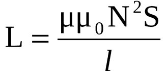
Finite Length Solenoid
The solenoid is a long and thin coil whose winding thickness is much less than its diameter. In this case, calculations are made using the same formula as the current strength, only the magnitude of the magnetic flux will be determined as follows: Ф = µ0NS / l, where:
- µ0 is the magnetic permeability of the medium, determined from look-up tables (for air, which is the default value in most calculations, it is 0.00000126 henry/meter);
- N is the number of coil turns;
- S is the cross-sectional area of the chain, measured in square meters;
- l is the length of the solenoid in meters.
The self-inductance coefficient of the solenoid can also be calculated according to the method for determining the magnetic flux energy of the field. This is a simpler option, but it requires some values. Formula for determining inductance: L = 2W / I 2, where:
- W is the magnetic flux energy, measured in joules;
- I is the current strength in amperes.
Toroidal core coil
In most cases, the toroidal coil is wound on a core made of a material with high magnetic permeability. In this case, the infinite length straight solenoid formula can be used to calculate the inductance. It has the following form: L = N µ0 µS / 2 πr, where:
- N is the number of coil turns;
- µ—relative magnetic permeability;
- µ0—magnetic constant;
- S is the cross-sectional area of the core;
- π is a mathematical constant equal to 3.14;
- r is the average radius of the torus.
Sources
- https://NpfGeoProm.ru/teoriya-i-opyt/sposoby-izmereniya-induktivnosti.html
- https://sto82.ru/elektroteoriya/metody-izmereniya-induktivnosti.html
- https://TokMan.ru/praktika/metody-izmereniya-induktivnosti.html
- https://supereyes.ru/articles/multimetry-i-testery/rlc-izmeritel-kak-vybrat/
- https://DiesElit.ru/osnovy/kak-izmerit-induktivnost-katushki-multimetrom.html
- https://drova-pil.ru/novosti/proverka-induktivnosti-multimetrom.html
- https://TeploDom24.ru/teoriya-i-praktika/kak-izmerit-induktivnost-katushki.html
Purpose and device
In some devices, chokes are installed in order to pass pulse currents of a certain frequency range. This range depends on the design of the inductor, that is, on the wire used in the coil, its cross-section, the number of turns, the presence of a core and the material from which it is made.
Structurally, the inductor is an insulated wire wound around a core. The core can be metal, made up of insulated plates, or ferrite. Sometimes the choke can be made without a core. In this case, a ceramic or plastic frame for the wire is used.
The throttle valve is present in the carburetor. It regulates the supply of the combustible mixture, representing a potentiometer. To check the throttle sensor in a car, determine whether the input voltage of the device corresponds to the throttle position .
The multimeter is set to dialing mode. The sensor connector contacts are connected to the multimeter probes and create the appearance of the damper moving (with your fingers). At the same time, check how the sensor reacts in the extreme positions of the damper. There should be a clear signal without wheezing.