One of the main elements of a large number of lighting devices is a ballast, denoted by the abbreviation electronic ballast. The component has features that are best known before connecting to the luminaire. Let's consider the electronic ballast circuit.
The main function of electronic ballasts is to convert alternating current into direct current. In another way, electronic ballast for gas-discharge lamps is also called a high-frequency inverter. One of the advantages of such devices is their compactness and, accordingly, low weight, which further simplifies the operation of fluorescent light sources. And the electronic ballast does not create noise during operation.
An electronic ballast, after connecting to a power source, provides current rectification and heating of the electrodes. In order for the fluorescent lamp to light up, a certain voltage is applied. The current is adjusted automatically, which is implemented using a special regulator.
Electronic ballasts for fluorescent lamps are divided into groups that differ in functionality: analog; digital; standard.
Expert opinion
Viktor Pavlovich Strebizh, lighting and electrical expert
Any questions ask me, I will help!
Some believe that due to the poor quality of electricity supplied in Russia, electronic ballasts too often fail, so chokes are preferred to them. If there is something you don’t understand, write to me!
What is electronic ballast and what is it for?
The use of electronic starting and control equipment or apparatus (abbreviated electronic ballasts) provides a significant increase in the useful life of lighting equipment of this type.
Electronic ballasts are the next round of development of lamp ignition systems. The electronic ballast is produced as a separate module with contacts for supplying power supply and contacts for connecting one or more lamps. This unit replaced a simple but outdated circuit with a throttle and starter. All modern lamps are usually equipped with this design.
Table of main faults
The main types of malfunctions that occur in chokes in practice are summarized in the table.
| Type of malfunction | What does it lead to? | External manifestation |
| Broken coil winding or internal wiring | Electrical circuit break | The lamp does not light (not even blinking) |
| Interturn closure | Loss of inductance, decrease in reactance | Burnout of lamp spirals (including repeated burnout after replacement), blinking without stable ignition |
| Short to body | Creates a ground fault in a network with a protective conductor | If a PE conductor is connected, it causes overcurrent and tripping of the protective device. If there is no protective grounding in the network, it may not manifest itself, but the mains voltage is present on the device body. |
| Loss of ferromagnetic properties of the coil core (as a result of overheating, etc.) | Loss of inductance, decrease in reactance | Burnout of lamp spirals (including repeated burnout after replacement), blinking without stable ignition |
Electronic ballast device
An electronic ballast is a complex electronic device. Includes:
- Interference filter: necessary to level out the influence of interference from and into the electrical network;
- Rectifier: needed to convert AC to DC;
- Optional: power corrector;
- Anti-aliasing filter: used to reduce ripple;
- Inverter: increases the voltage to the required level;
- Ballast: analogue of an electromagnetic choke.
In some models, the inverter can be supplemented with a brightness control. To do this, you need an external dimmer (either manual or automatic based on a photoresistor). A lot of schemes have been developed. The element base of electronic ballasts for daytime fluorescent lamps is very diverse: from powerful field-effect transistors in a bridge circuit with loads of hundreds of watts, to driver microcircuits in low-power lamps. But nevertheless, the operating algorithm is the same.
In a simplified form for one fluorescent lamp, the diagram looks like this:
Those. the circuit consists of only two components: a fluorescent lamp and an electronic starter. From an electrician's point of view, this is much simpler than the classic lamp circuit using an electromagnetic choke and starter. Terminals N and L are supplied with mains voltage. Ground pin – grounding. For electronic ballasts to operate, connecting a grounding contact is not mandatory and serves only for safe operation.
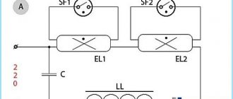
The connection diagram for two lamps is similar.
There are no additional elements in it; the circuit is supplemented only by a second lamp, the terminals of which are connected directly to the electronic unit.
Electronic ballast circuits are complex and consist of many electronic components. It is very difficult for a person without an engineering education to understand the diagram. In addition, not every electrician will be able to understand the internal structure.
One of the options for the electronic ballast circuit diagram
This is a fairly simple circuit for an electronics engineer. In a simplified sense, the scheme works as follows. Rectification is carried out by a full-wave rectifier - a diode bridge. Ripple smoothing is performed by an electrolytic capacitor designed for a voltage higher than the mains voltage, since the amplitude value of the sinusoid for the alternating current mains is approximately one and a half times higher than the mains voltage (√2*220V). The remaining processes are controlled by the microcircuit. Field-effect transistors are responsible for supplying voltage to the lamps. Then the converter operates autonomously, the frequency does not change.
Knowledge of electronics allows you to create a power supply circuit for a fluorescent lamp from low-voltage sources. The scheme turns out to be quite compact. The most important thing is to wind the transformer correctly.
Schematic diagram of powering a fluorescent lamp from a low-voltage source
Operating principle of the starter
Whatever circuit is used to start a fluorescent lamp. The general operating principle remains unchanged. In principle, similar processes occur when using a throttle and starter. There are only three phases:
- Initial heating of the electrodes. In electronic ballasts this occurs by a fairly gentle increase in voltage on the tungsten filaments.
- Arson. At this moment, the circuit delivers a high-voltage pulse (usually about one and a half kilovolts). This is enough for electrical breakdown of gas and mercury vapor. The ignition voltage of fluorescent lamps is significantly higher than the combustion voltage.
- Combustion. After a high-voltage pulse, the circuit reduces the voltage to that required to maintain the glow discharge. The AC frequency at the electrodes can reach 38 kHz depending on the circuit.
In electronic ballasts, the igniting impulse is provided by an electronic circuit. In the classical scheme - due to the energy accumulated by the inductor. Warming up of the electrodes is also provided by electronic ballasts. With a starter switching circuit, the electrodes warm up at the moment the starter contacts close. It can be replaced with a push button.
Connection diagrams
The development of such devices was carried out to minimize the design of the lamp and replace the large inductor and starter with one single module, which is connected to the AC power supply and to the electrodes of the fluorescent lamp.
Electronic ballasts are devoid of all the disadvantages of classical connection schemes.
There are modules designed to simultaneously connect four lamps.
Connecting electronic ballasts to four lamps
As is the case with one or two lamps, the circuit does not require any additional elements. The electronic ballast module is connected directly to the fluorescent lamp.
Connection diagram for electronic ballasts with one lamp
Connection diagram for electronic ballasts 4x18 W (Example: Navigator NB-ETL-418-EA3)
Source: vamfaza.ru
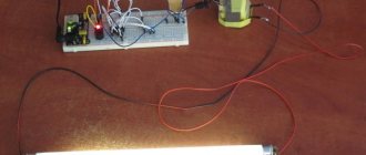
Make it yourself
Tubular luminaires with a length of 1200 mm are inexpensive and can illuminate large areas. The lamp can be made with your own hands, for example, from 2 lamps of 36 W each.
- The body is a rectangular base made of non-combustible material. You can use a used lamp that no longer requires repair.
- Electronic ballasts are selected according to the power of the lamps.
- For each lamp you will need 2 G13 sockets, stranded wire and fasteners.
- Lamp sockets are attached to the body after selecting the distance between them.
- Electronic ballasts are installed in the zone of minimal heating from the lamps (usually closer to the center) and connected to the sockets. Each unit is produced with a connection diagram on the case.
- The lamp is mounted on the wall or ceiling with a connection to a 220 V power supply via a switch.
- It is advisable to use a transparent cap to protect the lamps.
Checking the serviceability of the fluorescent lamp and its elements
Lamps of this type (LDS) belong to the class of fluorescent devices used for lighting. They have a number of advantages compared to incandescent lamps. At the same time, the lamp itself is only an integral part of the lighting device, is used as an emitter and works as part of a circuit together with ballasts. The device is far from trouble-free in terms of malfunctions that arise during its operation. To troubleshoot problems that arise, you need to be able to check a fluorescent lamp with a tester.
How to choose the right one
Before choosing a device for lighting lamps, pay attention to the following characteristics:
Type, power and number of lamps in the lighting scheme. The specification sheet for an electronic fluorescent ballast will indicate what types and configurations of fixtures are designed to operate the ballast. Start type - instant or programmed. If the lighting system is subject to frequent switching due to occupancy sensors or other factors, select “programmed start.” Otherwise, "instant" is the best choice. Ballast factor. The usual ballast factor (0.77 to 1.1) is the default value for most general lighting. A low ballast factor (1.1) is useful when the goal is to increase light output for areas such as warehouses or large retail stores. In this case, the user will receive approximately a 10% increase in luminous flux compared to the nominal illumination of the device. Input voltage. Some EBs provide universal voltage, others specific voltage. In any case, check the input voltage requirements - 120/277/347 V. Minimum initial temperature. Ballast specification sheets include temperatures that will vary depending on the type of fixture being controlled by the ballast. For example, EB can show a minimum initial temperature from −17 C to +30 C. Obviously, the variations are quite significant. Therefore, when choosing an EB, they proceed from the minimum and maximum air temperatures in the room. The normal connection diagram is parallel. This allows other lights to remain lit even if one bulb in the fixture goes out. Anti-stratification control: Strata are unwanted bright and dim areas that can form a standing wave structure along the entire length of the fixture. Streaks are more likely to occur when the lamp is operated at low temperatures. Manufacturers have developed ways to minimize these areas and often refer to the anti-stripping feature in the EB specification. Sound rating. An EV with a rating of “A” will hum quietly, with a rating of “D” it will cause a pronounced noise
The importance of sound assessment depends on the purpose of the premises. In libraries, LLs with the quietest ballast are installed, while this parameter is not so important for warehouses. LED Transition: Some EV manufacturers have lists of instant and programmed starting ballasts that they call "LED Ready". Manufacturer's warranty.
Why do fluorescent lamps burn out?
The lamp itself is a glass bulb of various geometric shapes, made of fragile quartz glass. Its inner walls are covered with phosphor - a material capable of converting the radiation spectrum of ultraviolet wavelengths into the visible part of radiation - daylight. Quartz loses its transparency over time.
External mechanical influences on the flask can lead to the appearance of microcracks in its structure, which can result in air entering the sealed cavity. This leads to burnout of the LDS. To glow, a glow discharge is required inside the housing, which is provided by the cathodes of the device, which are tungsten filaments in the form of spirals heated by electric current.
They are coated with a layer of alkali metal to extend the life of the lamp, which crumbles when turned on and off frequently. This, in turn, leads to overheating of the cathode and its failure. Over time, the electrode's emissivity, or its ability to emit electrons from its surface, decreases. Their number is no longer capable of supporting a glow discharge.
Troubleshooting and Troubleshooting
To begin with, we must remember that an electroluminescent lamp performs its lighting functions only when all its components work in harmony - the lamp itself, the ballast, which can be either electromechanical or electronic. Thus, the reasons for the malfunction of the lamp can be either in the circuitry of the ballasts, or it can be a failure of the LDS due to its aging or violation of operating conditions.
It is best to check a fluorescent lamp (lamp) if you have a working analogue. It is necessary to provide convenient access to all its components. In this way, you can correctly analyze the malfunction and give recommendations for elimination, even if you repair it yourself. We'll tell you how to check a fluorescent lamp at home.
Integrity of electrode spirals
The electrode spirals are located inside the gas-filled LDS tube and during production are soldered to the legs of the lamp bases. They are located in the end parts of the flask. Thus, using a multimeter in resistance measurement mode, you can ring a fluorescent lamp.
Electronic ballast for fluorescent lamps: connection instructions
At the moment, the consumer has not yet appreciated all the advantages of the improved trigger mechanism. The most important reason is the high price level for equipment of this type. You can find out about the motion sensor for turning on the light and tips on how to choose here.
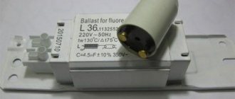
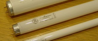
The photo shows an electronic ballast for fluorescent lamps
Principle of operation
The whole principle of operation of fluorescent lamps with electronic ballast comes down to the fact that the electric current passes through the rectifier and enters the buffer zone of the capacitor. Afterwards the voltage is supplied to the inverter
The microcircuit is triggered at a voltage level of 5.5 V. After the voltage in the system reaches 12 V, the system enters the next phase. Preheating occurs. The electronic control unit is needed to prevent the lamp from operating incorrectly.
At the third stage, the frequency response of the half-bridge decreases, and the voltage is 600 V. Ignition occurs in 1.7 seconds. If the start-up is incorrect, the filament burns out. See the guide on how to properly solder with a soldering iron here: https://howelektrik.com/elektrooborudovanie/instrumenty/payalniki/rukovodstvo-kak-pravilno-payat-payalnikom.html.
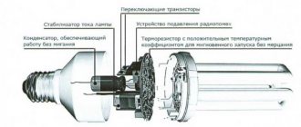
Device
Directly on the electronic ballast board is located:
- A filter that prevents the spread of electromagnetic interference.
- Rectifier - converts direct electrical current into alternating current.
- Anti-aliasing filter.
- Power factor correction.
- Half-bridge inverter.
- Protection against voltage surges.
- Throttle.
Types and characteristics
At the moment, you can use the following ballast options for fluorescent lamps:
- electronic ballasts for tubular fluorescent lamps - in this case, the electronic ballast makes it possible to continuously operate and “produce” diffused light, and on top of everything else, such a device has increased energy efficiency.
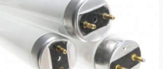
The photo shows an electronic ballast for tubular fluorescent lamps
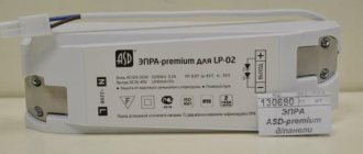
Ballast for T8 Navigator fluorescent lamps in the photo
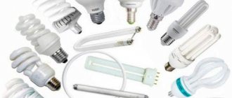
The picture shows a compact fluorescent lamp with electronic ballast
Integrated controllers for fluorescent lamp ballasts in the photo
Scheme
The figure shows a diagram of an electronic ballast for 4 fluorescent lamps
- Inclusion
- Preheat
- Arson
- Combustion
At the moment, the electronic ballast circuit for fluorescent lamps with a power of 36w is very common
There is also another balance option for turning on fluorescent lamps - inductive ballast. Its work is based on electromagnetic induction.
Switching diagram for fluorescent lamps with inductive ballast
Connection
Connecting a fluorescent lamp to an electronic ballast in the diagram
- Prepare EB and lamp.
- Remove the old filling from the lamp. Attach the EB box.
- On the one hand, electronic devices connect to the network - two wires.
- At the output from the EB, I connect the wires to the two poles of the lamp.
- Connect the device to an outlet.
Advantages
Electronic devices have many advantages over electromagnetic ballasts, we list the main ones:
- electronic ballasts do not cause flickering of the LDS during its operation and do not create extraneous noise;
- a circuit based on electronic elements consumes less energy, weighs lighter and is more compact;
- the possibility of implementing a circuit that produces a “hot start”, in this case the cathodes of the LDS are preheated. Thanks to this switching mode, the service life of the source is significantly extended;
- The electronic ballast does not require a starter, since it is itself responsible for generating the voltage levels necessary for starting and operation.
Electronic ballast for fluorescent lamps: connection instructions
At the moment, the consumer has not yet appreciated all the advantages of the improved trigger mechanism. The most important reason is the high price level for equipment of this type. You can find out about the motion sensor for turning on the light and tips on how to choose here.
The photo shows an electronic ballast for fluorescent lamps
Principle of operation
The whole principle of operation of fluorescent lamps with electronic ballast comes down to the fact that the electric current passes through the rectifier and enters the buffer zone of the capacitor. Afterwards the voltage is supplied to the inverter
The microcircuit is triggered at a voltage level of 5.5 V. After the voltage in the system reaches 12 V, the system enters the next phase. Preheating occurs. The electronic control unit is needed to prevent the lamp from operating incorrectly.
At the third stage, the frequency response of the half-bridge decreases, and the voltage is 600 V. Ignition occurs in 1.7 seconds. If the start-up is incorrect, the filament burns out. See the guide on how to properly solder with a soldering iron here: https://howelektrik.com/elektrooborudovanie/instrumenty/payalniki/rukovodstvo-kak-pravilno-payat-payalnikom.html.
Device
Directly on the electronic ballast board is located:
- A filter that prevents the spread of electromagnetic interference.
- Rectifier - converts direct electrical current into alternating current.
- Anti-aliasing filter.
- Power factor correction.
- Half-bridge inverter.
- Protection against voltage surges.
- Throttle.
Types and characteristics
At the moment, you can use the following ballast options for fluorescent lamps:
- electronic ballasts for tubular fluorescent lamps - in this case, the electronic ballast makes it possible to continuously operate and “produce” diffused light, and on top of everything else, such a device has increased energy efficiency.
The photo shows an electronic ballast for tubular fluorescent lamps
Ballast for T8 Navigator fluorescent lamps in the photo
The picture shows a compact fluorescent lamp with electronic ballast
Integrated controllers for fluorescent lamp ballasts in the photo
Scheme
The figure shows a diagram of an electronic ballast for 4 fluorescent lamps
- Inclusion
- Preheat
- Arson
- Combustion
At the moment, the electronic ballast circuit for fluorescent lamps with a power of 36w is very common
There is also another balance option for turning on fluorescent lamps - inductive ballast. Its work is based on electromagnetic induction.
Switching diagram for fluorescent lamps with inductive ballast
Connection
Connecting a fluorescent lamp to an electronic ballast in the diagram
- Prepare EB and lamp.
- Remove the old filling from the lamp. Attach the EB box.
- On the one hand, electronic devices connect to the network - two wires.
- At the output from the EB, I connect the wires to the two poles of the lamp.
- Connect the device to an outlet.
Switching on two fluorescent lamps through a ballast involves parallel connection in the circuit. Only in this way will all lighting elements receive sufficient voltage for uniform operation of the devices.
Scheme for connecting two fluorescent lamps through ballast
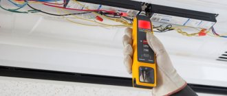
How to check electronic ballast for fluorescent lamps?
The picture shows a device for testing lamps, including fluorescent ones
Malfunctions and repairs
It goes without saying that any equipment can sooner or later break down or malfunction. In other words, any device sometimes requires repairs and additional maintenance.
The photo shows the electronic ballast disassembled
If, due to a malfunction of the ballast for fluorescent lamps, smoke starts to appear, then it will be necessary to completely replace this element, because the smoke indicates that the component has burned out.
Repair of electronic ballast in the photo
Cost of electronic ballast for fluorescent lamps
If you need to purchase electronic ballast for fluorescent lamps, you need to contact stores that specialize in electronics or lighting equipment. The cost of this type of equipment will vary from 150 to 1200 rubles.
Where to buy electronic ballast for fluorescent lamps?
Where to order in Moscow:
- Online store Rulight.ru Moscow, Konstantin Simonov St., 5 Contact phone: 8 (495) 7883548 (multi-channel);
- Trading company Ampertorg Moscow, st. Tovaricheskaya house 6 k.1 Contact phone number;
- Online store Elektropara Moscow, st. Dokukina 10 building 10 Contact phone number.
Where to order in St. Petersburg:
- Torgovaya St. Petersburg, st. Bestuzhevskaya, 10, office 2604 (TC “Bestuzhevsky Dvor”) Contact phone number;
- Snabelektro company, St. Petersburg st. Vatutina house 17, Lit.B, Contact phone;
- Energy Saving Technologies Company, St. Petersburg, 192148 St. Petersburg, Elizarova Ave., 38 letter R, Contact phone: +7-812-3654217.
Video
Watch the video for a description of the 36 W electronic ballast:
So it turns out that this type of lamp, when using an electronic balance, begins to work several times better. In addition, the response period of the device and its operating time are significantly reduced.
Source: howelektrik.com
Checking the serviceability of the fluorescent lamp and throttle
One of the most popular sources of artificial lighting is fluorescent lamps. They consume 5-6 times less energy than standard incandescent lamps, but still shine with the same brightness. LED lamps with drivers are more economical, but due to their high cost, they have not been able to displace fluorescent lamps (FLL) from the market. With prolonged use, fluorescent lamps may lose their functionality. It is possible to fix such problems, but to do this you need to know how to check a fluorescent lamp, including using a multimeter.
The best manufacturers of electromagnetic devices
According to statistics, the best electromagnetic devices are from the famous brand E.Next. This is not surprising; this company produces high-quality modules that are distinguished by their reliability and durability. The products are made in accordance with the strict requirements that apply to goods of this class. E.Next provides a guarantee for the entire line of products and also offers its customers quality service. The client can contact one of the many call centers and ask the technical support staff a question.
The European company Philips is not inferior to its colleagues in the production of electromagnetic ballasts. Products of this brand are considered one of the most reliable and effective on the market. Therefore, choosing the necessary model for an incandescent lamp will not be difficult.
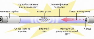
Design and principle of operation of fluorescent lamps
Many of the advantages of LDS are due to the fact that they are gas-discharge devices in which ultraviolet radiation is generated due to electrical discharges in mercury vapor.
There is only one peculiarity here - visible illumination from the lamp occurs only after the ultraviolet radiation is modified. Such a transformation is possible only when using those compounds that contain calcium halophosphate or other compounds with the presence of phosphors.
Based on the principle of operation, LDS can be equated to gas-discharge lighting sources. An inert gas is placed in a glass flask, after the air has been pumped out of it, and then 30 mg of mercury is added to the gas. Spiral-shaped electrodes, similar to an incandescent filament, are installed at both edges of the vessel. They are soldered on each side to 2 contact legs, which are placed in dielectric-type plates. The inner surface of the tube is covered with a layer of phosphor.
The daylight is turned on using a ballast - electromagnetic or electronic type. The electromagnetic device includes a main element - a choke. This is a ballast type resistance in the form of an inductive coil with a metal core, which is connected in series with a fluorescent lamp.
The choke is necessary to maintain uniformity of discharge and adjust the current if necessary. When the light bulb turns on, the inductor suppresses the starting current until the spiral filaments heat up, and then produces the maximum voltage from self-induction, as a result of which the LDS ignites.
Making your own probe
It is difficult to ring a small LED with a standard probe, so for comfortable use of the multimeter you can make it yourself. Several elements are used for this.
Sewing needle
You will need:
- housings from black and red handles for handles;
- plugs and cable;
- steel sewing needles 35-45 mm in length and 0.8-1 mm in diameter;
- scraps of copper wire (pair - 250-300 mm long and pair - 120-150 mm long);
- rosin or alcohol rosin.
The manufacturing process is carried out in stages:
- The wire is cut and tinned with solder.
- The needles are tinned with solder so that there is 8-10 mm left to the sharp parts.
- Conductors 0.3-05 mm in diameter are attached next to the ears of the needles, and then wound in turns to the tinned area.
- The winding is covered with solder.
- The tinned cable is bent in half around a screwdriver. The free sections are fastened together in a pigtail. The resulting loop is bent at an angle.
- The conductors are attached to the needles with a soldering iron.
- Plaque is removed from all joints using alcohol.
- A thread is wound in the center of the needles until bulges appear. They will need to be coated with Moment glue and inserted into the tips of the handle bodies, fixing them as evenly as possible.
- After the glue has dried, epoxy is poured into the cavities, which hardens for 24 hours.
- The ends of the probes are tinned and soldered to the plugs.
- To protect the shell from friction, problem areas are placed in a heat-shrink tube.
- Flexible conductors are made of red and black copper wires 1 m long.
- Tips with needles are connected to flexible conductors with a soldering iron. The handle pieces are fastened together. The optimal wire cross-section is 1.3 mm².
Plug
Dismountable plug
You will need:
- Soviet electrical plug with brass pins;
- old multimeter probes;
- plastic tube;
- wire with thick copper cores;
- banana plugs.
Making a probe from a plug
Progress:
- Removing the pins from the plug by unscrewing the top bolt.
- Removing the base from old probes - the pins can be removed with pliers.
- Separating the bent part of the pins with a file and turning them so that they fit with force into a piece of plastic pipe.
- Separating and stripping speaker wire.
- Tinning of cable ends and pin ends at soldering points.
- Inserting a wire into the base of the old multimeter leads and soldering a brass plug to it.
- Pulling the cable back and fixing the area where it enters the tube with heat shrink.
Reasons for burnout of fluorescent lamps
Often the LDS burns out, which makes it similar to a traditional incandescent lamp. When turned on, an arc of electricity is formed in the bulb, as a result of which the spiral-shaped tungsten electrodes become very hot. High temperature surges lead to destruction and burnout of the threads.
To extend the service life, a layer of active alkali metal is applied to the tungsten filament. The discharge between the electrodes is stabilized and the temperature decreases, thanks to which the thread lasts much longer.
Frequent switching on/off of the lamp entails the destruction of the protective layer, it simply falls off. The discharge passing through the bare filaments heats the spiral at weak points, resulting in burnout.
Checking with a digital tester
Using a digital tester, you can check the integrity of the filaments. This can be done both in the dialing mode and in the resistance testing mode. It is necessary to set the multimeter to the desired mode and check the spiral at both ends of the tube.
In the dialing mode, if the spiral is working properly, the tester will produce a characteristic sound - a buzzer.
In the resistance test mode, if the spiral is working properly, the multimeter indicator will display a value of 5-10 Ohms.
Burnout of heating filaments is the most common failure of fluorescent lamps, which can be easily detected using a digital tester.
Troubleshooting and Troubleshooting
The LDS is faulty in the following cases:
- does not turn on;
- flickers temporarily before turning on;
- flickers for a long time, but does not turn on;
- buzzes;
- flickers when burning.
Integrity of spiral electrodes
You can test the spiral electrode for the presence of resistance using a multimeter. The device is set to resistance measurement mode, and after that the probes are applied to the legs of the flask on both sides.
If the spiral is faulty, the multimeter will show zero resistance - the thread is broken. A whole spiral always shows a small resistance - up to 10 ohms. If at least one of the spirals is faulty, the lamp must be replaced. It cannot be restored.
Faults in the electronic ballast
To check the serviceability of the electronic ballast, it must be replaced with a working one. If the lamp lights up, it means that it was the cause of the breakdown. You can fix a broken ballast yourself. First you need to replace the fuse with a similar model with the same characteristics. If the threads glow weakly, it means there is a breakdown in the capacitor between them. It is also replaced by a similar one, but with an operating voltage of 2 kV. weak models will burn out quickly.
Transistors may burn out due to voltage surges. They need to be changed. You can take new ones from old ballasts. After replacement, you need to check the fluorescent lamp using a 40 W lamp.
How to check the choke of a fluorescent lamp
Before checking the choke of a fluorescent lamp with a multimeter, you need to familiarize yourself with the main signs of its failure:
- hum of a lighting fixture;
- the lamp turns on and goes out after a while, getting dark around the edges;
- LDS overheats;
- “snakes” appear inside the tube;
- The lamp flickers a lot.
To check the choke for operability, you need to remove the starter from the lamp, and then close the contacts in its socket. Then the lamp is removed and the contacts in both sockets are also short-circuited. The multimeter is set to measure resistance, after which its probes are connected to the contacts in the lamp socket. If there is a break, the device will show endless resistance. If there is an interturn short circuit, the device will show a zero value.
How to check the starter
If the lamp begins to flicker immediately after switching on, but does not light up, the starter has failed. It will not be possible to test it separately from the LDS, since without voltage its contacts are open.
Checking the serviceability of the starter is possible using another method - by connecting it in series with an incandescent lamp to a standard electrical network.
The main reason for failure is that the bimetallic plate wears out greatly.
How to check the capacitance of a capacitor with a tester
If the LDS capacitor is faulty, its efficiency indicator decreases to 35-40%. For lighting devices with a power of no more than 40 W, a capacitor with a capacity of 4.5 μF is sufficient. If it is less than this norm, the efficiency will be reduced; if it is more, the lighting will blink.
To carry out the measurement, the capacitor must be ringed with a multimeter. When the probes touch the outputs of a part, the device demonstrates endless resistance. When this indicator is less than 2 MΩ, this is a symptom of significant current leakage.
Features of diodes
A standard diode is a component of the electrical network and acts as a pn junction semiconductor. Its structure allows current to pass through the circuit in only one direction - from the anode to the cathode (different ends of the part). To do this, you need to apply “+” to the anode and “-” to the cathode. Due to this feature of the product, if you suspect a breakdown, it can be checked with a tester or multimeter.
Various types of diodes.
Today in radio electronics there are several types of diodes: Types of diodes:
- Light-emitting diode. When an electric current passes through such an element, it begins to glow as a result of the transformation of energy into a visible glow;
- protective or regular diode. Such elements in the electrical network act as a suppressor or voltage limiter. One of the varieties of this element is the Schottky diode. It is also called a Schottky barrier diode. Such an element, when connected directly, gives a low voltage drop. In Schottky, instead of a pn junction, a metal-semiconductor junction is used.
It will be interesting Ways to check transistors for performance
Here is a small selection made up of specific diodes and their corresponding Vf values, which were obtained when testing them with a multimeter. All diodes were previously checked for serviceability.
Table of measurements of diode characteristics using a multimeter.
If ordinary parts and LEDs are used in the vast majority of electrical appliances, then Schottky ones are used mainly in high-quality power supplies (for example, for devices such as computers). It is worth noting that testing a conventional diode and a Schottky diode is practically no different, since it is carried out according to the same principle. Therefore, there is no need to worry about this issue, because the operating principle of both Schottky and conventional diodes is identical.
Schottky diode
Being a component of an electronic circuit, such semiconductor elements often fail. The most common reasons for their failure are:
- exceeding the maximum permissible direct current level;
- excess reverse voltage;
- poor quality part;
- violation of the device operating rules established by the manufacturer.
Moreover, regardless of the cause of loss of performance, failure can be directly caused by either a “breakdown” or a short circuit. In any case, if there is an assumption that the electrical network has failed in the semiconductor area, it is necessary to diagnose it using a special device - a multimeter. Only to carry out such manipulations you need to know how to check the diode using it correctly.
What is a multimeter
A multimeter is a universal device that performs a number of functions:
- measures voltage;
- determines resistance;
- checks wires for breaks.
It will be interesting How to make a power regulator on a triac with your own hands
Using this device you can even determine the suitability of the battery.
Checking the LEDs in the lamp.
How to test a diode
After we have figured out the semiconductors of the electrical circuit and the purpose of the device, we can answer the question “how to check the diode for serviceability?” The whole point of checking diodes with a multimeter is their one-way electrical current carrying capacity. If this rule is observed, the electrical circuit element is considered to function correctly and without failures. Conventional diodes and Schottky diodes can be easily tested using this device. To check this semiconductor element with a multimeter, you need to do the following manipulations:
- you need to make sure that your multimeter has a diode test function;
- If such a function is available, we connect the probes of the device to the side of the semiconductor from which the “ringing” will be carried out. If this function is missing, then use the switch to switch the device to 1 kOhm. You should also select the mode for measuring resistance;
- the red wire of the measuring device must be connected to the anode end, and the black wire to the cathode end;
- after this, you need to observe changes in the forward resistance of the semiconductor;
- we draw conclusions about the presence or absence of voltage
The unit can then be switched to check for leaks or high circuits. To do this, you need to change the location of the diode output. In this state, it is also necessary to evaluate the obtained values of the device.
Turning on a fluorescent lamp without a choke
A burnt-out fluorescent lamp can be returned to work if it is connected to the circuit using constant voltage, excluding the starter and throttle element. Using a full-wave rectifier with voltage doubling will help here. If after some time the brightness of the lamp decreases, it must be turned over in the lamp, as a result of which the connection poles will change.
This scheme involves the use of radioelements with a voltage value of no more than 900 V. This is the value that the LDS reaches at startup.
Connection diagram for burnt out lamps
Fluorescent lamps often become unusable due to filament burnout. You can restore a second life to such a lamp using an unconventional starting scheme, repeatedly tested by folk craftsmen.
From the table you can find out the nominal values of radioelements for LDS with different powers. Limiting resistors R1 must be made of wire.
You can repair LDS at home if you follow the diagrams and follow certain instructions. Such knowledge makes it possible to extend the operational period of the lighting device.
Source: strojdvor.ru
Halogen bulbs
To begin with, let us recall that a halogen lamp is classified as a thermal lighting source. It, like a regular light bulb, has a spiral. Under the influence of current, it heats up and produces light radiation. Increased brightness and saturation is created due to the presence in the flask of a gas mixture, which includes halogens (hence the name). This type of lamp is widely used to create spot lighting or backlighting.
What to do if a halogen light bulb stops working?
- First, you should check the voltage in the base of the lighting fixture;
- If the voltage is ok, check the light bulb.