A light-emitting diode, like a person, needs to eat properly. Only in this case does it guarantee many years of trouble-free operation. LEDs have a nonlinear current-voltage characteristic similar to a conventional diode. Therefore, they must be powered by a stable current - this is one of the key principles. If this is not followed, the consequences for LEDs can be dire.
To determine which power plan will be optimal in a particular case, you first need to know the initial data:
- LED parameters standardized by the manufacturer;
- power supply parameters (220 V mains, battery, batteries or something else).
A little theory
An LED requires a constant voltage or current to operate properly. They should be:
- Constant in direction. That is, the current in the LED circuit when voltage is applied must flow from the “+” of the voltage source to its “–”.
- Stable, i.e. constant in value, during the operating time of the diode.
- Not pulsating - after rectification and stabilization, the values of constant voltage or current should not change periodically.
Diagram of the voltage waveform at the output of a full-wave rectifier when filtered by an electrolytic capacitor (in the diagram there are black and white rectangles marked “+”). The dotted line is the voltage at the rectifier output. The capacitor is charged to a half-wave amplitude and gradually discharged across the load resistance. “Steps” are pulsations. The ratio of the step and half-wave amplitudes as a percentage is the ripple factor.
For LEDs, the available voltage sources were initially used - 5, 9, 12 V. And the operating voltage of the pn junction is from 1.9-2.4 to 3.7-4.4 V. Therefore, turning on the diode directly is almost always its physical combustion from overheating with high current. The current must be limited by a current-limiting resistor, wasting energy on heating it.
LEDs can be switched on in series, several at a time. Then, by assembling a chain of them, the sum of their direct voltages can be used to almost reach the voltage of the power source. And “pay off” the remaining difference by dissipating it in the form of heat on a resistor.
When there are dozens of diodes, they are connected in series circuits that are connected in parallel.
Literature
1. GOST 15150-69 Machines, instruments and other technical products
Versions for different climatic regions.
Categories, conditions of operation, storage and transportation in terms of the impact of environmental climatic factors.
2. GOST R 51317.3.2.-2006 Emission of harmonic current components by technical means with a current consumption of no more than 16 A (in one phase). Standards and test methods.
Obtaining technical information, ordering samples, delivery - e-mail
•••
Types and main parameters of LEDs
In the diagram, the LED is indicated as a regular diode with two parallel arrows pointing outward, indicating its emitting nature. There are a large number of types of LEDs on sale, which differ in functionality, design, power, glow color and other properties.
Based on their purpose, LEDs are divided into two types - indicator and lighting.
Indicative:
- SMD LEDs;
- super bright Super Flux “Piranha”;
- DIP LEDs (Direct In-line Package);
- Straw Hat (“straw hat”).
Lighting:
- COB (Chip On Board) LEDs;
- SMD LED;
- filament (Filament LED).
Indicative
Indicator LEDs are characterized by low power and moderate brightness. They are used for color indication of operating modes of various devices and equipment, as well as for illumination of displays and instrument panels. Types of indicator LEDs:
- DIP LEDs. The emitter crystal is located in an output housing, which most often is a convex lens. The downside is the small radiation scattering angle.
- “Piranha” is an ultra-high brightness emitter with four pins, ensuring its convenient mounting on the board. Demanded for illuminating devices in cars and advertising signs.
- "Straw Hat" A cylindrical two-terminal device with a significant radiation scattering angle and an increased lens diameter. Used in decorative structures and alarm lights.
- SMD LEDs. Ultra-high brightness devices are housed in housings designed for SMT mounting. Their markings indicate dimensions in inches (hundredths thereof) or in mm. LED strips are manufactured based on SMD LEDs.
Lighting
Lighting LEDs are found in the design of lanterns, headlights, and strips. They differ in the power and brightness of the glow. Most lighting fixtures are housed in SMT mounting housings. Available in two varieties of white:
- cool white – cold;
- warm white – warm.
An SMD lighting LED is a heat-sinking substrate on which a emitting crystal treated with a phosphor composition is mounted.
LED pinout
The polarity of the LED - anode or plus and cathode - minus is easy to determine from the pictures:
In cylindrical cases, the cathode is indicated by a cut on the side, the anode has a longer lead, and the cathode has a shorter lead.
The cathode of SMD LEDs is indicated by a cut on the body.
In high-power COB LED arrays, “+” and “-” are pressed onto solder pads.
LED connection diagram
In the classical circuit, it is recommended to connect through a current-limiting resistor. Indeed, by choosing the right resistor or inductive reactance, you can connect a diode designed for a 3V supply voltage, even to an alternating current network.
We recommend reading: About connecting a voltmeter: diagram of connecting voltmeters to a circuit
The main requirement for power parameters is limiting the circuit current.
Since current strength is a parameter that reflects the density of electron flow through a conductor, if this parameter is exceeded, the diode will simply explode due to the instantaneous and significant release of heat on the semiconductor crystal.
Basic principles of connection
As mentioned earlier, the design of a light-emitting diode involves connecting them exclusively to a direct current source. However, since the working part of the LED is a semiconductor silicon crystal, it is very important to maintain polarity, otherwise the LED will not emit a luminous flux.
Each LED has technical documentation, which contains instructions and directions for correct connection. If there is no documentation, you can look at the LED markings. The marking will help you identify the manufacturer, and knowing the manufacturer, you can find the required datasheet, which contains information on the connection. Here, this is not a tricky piece of advice.
How to determine polarity?
There are only 3 ways to resolve the issue:
- Constructively. According to standards accepted throughout the world, on a regular LED (not SMD type), the long leg is always the “+” or the anode. For an LED to work, a positive half-wave must be supplied to it. And the short one is the cathode.
- Using a multimeter. To check, you need to set the device switch to the “Test” mode and install the red multimeter probe on the anode, and the black probe on the cathode. As a result, the LED should light up. If this does not happen, you need to change the polarity (black to the anode, and red to the cathode). If the result does not change, then the LED has failed (to establish a more accurate diagnosis, read how to check the LED).
- Visually. If you look closely at the LED, you can see 2 tips near the crystal. The larger one is the cathode, the smaller one is the anode.
We've sorted out the polarity, now we need to decide how to connect the LED to the network. For those who do not understand, read a detailed and interesting article on determining the polarity of an LED. In it we have collected all possible methods of checking, and even using a battery.
Briefly about efficiency
The efficiency of a lighting device is generally considered to be the ratio of the luminous flux produced (measured in lumens) to the electricity consumed (watts). A high-quality incandescent lamp has an efficiency of about 16 lumens per watt, a fluorescent (energy-saving) lamp is four times more efficient (64 lm/W), for long daylight lamps this figure is around 80 lm/W.
The efficiency of ultra-bright LEDs currently produced in large quantities is approximately the same as that of fluorescent lamps. Please note that we are talking about mass production. As for the theoretical limit for ultra-bright LED sources, it is determined by a threshold of 320 lm/W.
As many manufacturers promise, in the next few years the efficiency can be increased to 213 lm/W.
Connecting a light-emitting diode to a 220 V network
If you power the LED directly from 220 V with its current limited, then it will shine with a positive half-wave and go out with a negative half-wave. But this is only in the case when the reverse voltage of the pn junction is much greater than 220 V. Usually this is around 380-400 V.
The second way to turn on is through a quenching capacitor.
The mains voltage is supplied to the “bridge” using diodes VD1-VD4. Capacitor C1 will “extinguish” about 215-217 V. The remainder will be straightened. After filtering by capacitor C2, a constant voltage is supplied to the LED. Don't forget to limit the current through the diode with a resistor
Another connection diagram is with a half-wave rectifier based on a diode and with a limiting resistor of 30 kOhm.
ATTENTION! Most circuits with a direct connection to a 220 V network have a serious drawback - they are dangerous for damaging a person with high voltage - 220 V. Therefore, they should be used carefully, with careful insulation of all live parts.
Connecting LEDs to 220V voltage
The first thing you need to know when connecting to a 220V network is that for a nominal glow, a current of 20 mA must pass through the LED, and the voltage drop across it should not exceed 2.2-3V. Based on this, it is necessary to calculate the value of the current-limiting resistor using the following formula:
in which 0.75 is the reliability coefficient of the led, U pit is the voltage of the power source, U pad is the voltage that drops across the light-emitting diode and creates the luminous flux, I is the rated current passing through it, and R is the nominal resistance for regulating the passing current After appropriate calculations, the resistance value should correspond to 30 kOhm.
However, do not forget that a large amount of heat will be generated at the resistance due to the voltage drop. For this reason, it is additionally necessary to calculate the power of this resistor using the formula:
For our case, U will be the difference between the supply voltage and the drop voltage across the LED. After appropriate calculations, to connect one LED, the resistance power should be 2W.
After determining the rating and power of the resistance, you can assemble a circuit to connect one LED to 220V. For its reliable operation, it is necessary to install an additional diode that will protect the light-emitting diode from breakdown when an amplitude voltage of 315V (220*√2) occurs at the LED terminals.
The circuit is practically not used, since very large losses occur in it due to heat generation in the resistance. Let's consider a more efficient connection diagram to 220 V:
In the diagram, as we can see, a reverse diode VD1 is installed, which passes both half-waves to the capacitor C1 with a capacity of 220 nF, on which the voltage drops to the required nominal value.
Resistance R1 with a nominal value of 240 kOhm discharges the capacitor when the network is turned off, and does not play any role during operation of the circuit.
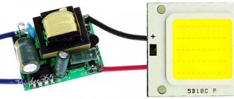
But this is a simplified model for connecting LEDs; most LED lamps already have a built-in driver (circuit) that converts 220V AC voltage into 5-24V DC voltage for their reliable operation. You can see the driver circuit in the following photo:
We recommend reading: Refinement of the Chinese super bright flashlight UltraFire XML-T6
LEDs, strips and their power supply from alternating current electric current
I probably won’t be wrong if I say that more than 90% of Russian residents know what LED strips are, when asked “can transformers from halogen lamps be used to power LED strips?” They will answer “no, you can’t!” The most common explanation will be the banal “electronic transformer is alternating current, but LEDs need constant current.” This is exactly what they tell us in stores, this is exactly the leitmotif of the vast majority of “professional” articles on this topic, which, in general, has taught people to spend significantly more money. Is this always justified and how do LEDs in the most common LED strips actually behave when powered by alternating current, we will try to find out in the process of reading this article.
I’ll immediately make a reservation that to designate “LED” I will continue to use the self-evident and completely natural abbreviation LED and will deliberately not use the English technical abbreviation LED (Light Emitting Diode) for this concept. In our current country, the lack of any proper technical training of managers and salespeople in stores has already led to littering and the appearance of such unnatural for technical language, foolish to hear and terrible to write letter combinations “leds”, “led'ы”, “ice”, or As I recently saw in the scrolling text - “LED LEDs”. Not only is “butter – buttery”, I just don’t want to echo and create this “word confusion”...
The ideological source for writing the study was the long-standing desire to refute unfounded and categorical statements about the inadmissibility of powering LEDs with alternating current. In general, the controversial nature of this statement certainly strikes the eye of any specialist (as well as a “non-specialist”) who understands that an LED, although it emits light, is first and foremost a DIODE. This means that it will still emit under the influence of alternating voltage, but only during its half-cycle.
Essentially, we will need to consistently answer three questions:
1) Will the electric vehicle be able to “start” when connecting a load in the form of semiconductor diodes; 2) If the ET starts, will the pulsed “alternating” electrical impact exceed the permissible parameters of the individual LEDs in the tapes. If it does exceed, then how long will the SD last in such conditions; 3) What is the economic efficiency of using ET in lighting designs on LED strips.
So, six months ago I just had a convenient opportunity to experiment.
I needed to light up the space in the drawers and desk cabinets in my workshop. After equipping the kitchen, I was left with 1.2 meters of single-color LED tape with a total power of about 17 W (Aztech 14 Watt/meter) and one electronic transformer from halogen lamps - EAC 12V 20-60 W, the most common and cheapest, bought for 74 rubles in July 2014. To begin with, to start the ET, I loaded it with an ordinary 20 W halogen lamp and then connected all 1.2 meters of strip in parallel (Fig. 1). As expected, the tape lit up. At the same time, the glow of the tape was uniform, of average brightness, without any flickering noticeable to the eye, which is not surprising, because The output meander of the ET is modulated according to the amplitude, barely noticeable to the eye, at a frequency of 100 Hz. During the experiment, turning off the lamp in such a circuit immediately led to the cessation of the glow of the LED strip, which indicated the impossibility of starting the ET on one half-wave voltage. Then I divided the tape into two sections and turned them on back-to-back (Fig. 2), which, according to the plan, was supposed to ensure the operation of the ET output stage in both half-cycles. At the same time, in order to eliminate the imbalance of currents in the opposite direction and overheating of the output winding of the ET due to the appearance of a constant component, I ensured equality (8 W) in the number of LEDs in both load arms. Immediately after connecting according to this scheme (Fig. 2), the transformer safely entered the generation mode, and both LED strips lit up evenly and were left for 1 hour, during which neither they nor the electric vehicle itself heated up at all, which rather indicated quite normal electrical modes than not.
So, the answer to the first question - will the EV start when replacing halogen lamps with LEDs - is positive.
Yes, it will start! If we ensure back-to-back connection of the strips as in Figure 2. And looking ahead...
Looking ahead, I will say that, as further experiment showed, an ET with a nominal minimum startup power of 20 W started up safely even with 10 W of the total LED load (5 W each in each shoulder).
Go ahead. Now we are trying to find an answer to the second question
of our research. But now experiments alone are not enough for us; we will need knowledge from TERCiE (Theory of Electrical Radio Circuits and Elements), which will ultimately allow us to assume: is it possible to power SD tapes for a long time in this mode without serious damage to their durability, if we talk about damage at all?
Let's start with the SD tape device. The tape consists of working sections connected in parallel (Fig. 3) of three emitters (indicated in the diagram - E) representing three separate LEDs under a common phosphor layer. Each diode (D in the diagram) of the emitter is connected in series in triads with diodes from other emitters and a resistor that sets the calculated operating point of the diodes (See Fig. 4).
The resistor in the triad is selected in such a way that, when powered by 12 V and the calculated operating point of the diode Upr = 3.3 V, Ipr = 14 mA, an excess voltage of about 2 Volts is extinguished on it.
By the way, interesting...
This arrangement of the triad is reliable and practical, because if a single LED in the triad fails, none of the emitters will turn off completely, but will continue to burn, albeit with a third less brightness. You can, of course, create a triad based on a single emitter (and such tapes are available on sale). In them, the working section that determines its cutting will be a fragment with a single emitter and a resistor, but in this case, the failure of a single LED in the triad will lead to the loss of glow by the entire emitter, which will be immediately noticeable in any lamp.
Having rummaged through the manufacturers of SMD LEDs, it is easy to find the electrical parameters of the used LEDs:
To complete the study, I additionally measured the current-voltage characteristic (CVC) of the working section of the tape (Fig. 5), and by simple recalculation I obtained the current-voltage characteristic for a separate LED (Fig. 6).
I hope you…
I hope you have no doubt that this could have been done physically, and the results would have been the same.
Fig.5
Fig.6
The current-voltage characteristics shown in the figures do not require additional explanation. I will only add that when the voltage is less than 2.35 V on a separate LED, its glow is completely absent, which corresponds to a supply voltage of the working area of about 7 V, and a supply voltage of 15.5 V on the tape is completely safe, because The current through a separate LED does not exceed normal operating 30 mA.
However, all these numerical expressions of operating parameters are relevant only for direct current. We are going to test the diode when exposed to alternating voltage, i.e. pulse voltage in different directions. However, with such a power supply, the maximum permissible values of currents and voltages on the diode can be several times, or even tens of times greater than the limits for direct current (this is well known and doubting managers can read lectures on thermal power plants) - it all depends on the duration and frequency of exposure. But here’s the problem: the output voltage of the ET has a rather complex shape, which does not allow it to be described mathematically within the scope of this article, and the performance characteristics of the LEDs are not provided with a section of absolute values for pulsed operating modes. Although, it is true, there is one parameter (Ipr imp), but for what pulse duration it is relevant - it is not clear, for what duty cycle of the effect this is applicable, one can also only guess.
The whole point is...
The thing is that the pn junction of a semiconductor, when operating on alternating (pulse) current, operates with a variable load. Current periods that cause heating and operation of the LED by emitting light waves are replaced by rest pauses (during which no current flows through the junction) and in which the semiconductor cools. And the question here is not so much the absolute value of the current through the semiconductor, but rather whether the semiconductor will have time to cool enough during the no-current pause to compensate for the heating that occurred during the current period. Those. prevent thermal breakdown. Here, I want to remind the “physics” of semiconductor failure. This will allow us to understand the essence of the ongoing processes. She, physics, is generally known, but still in her own words: the durability of any device is determined by its fault tolerance. Diode failures during normal operation occur in the event of thermal or electrical breakdown. Electrical breakdown, as a rule, occurs when the permissible reverse voltage (Urev) is exceeded. In this case, the diode loses the property of one-way conductivity and begins to conduct in both directions. In most cases, the electrical breakdown is reversible and the functionality of the device is restored.
But thermal breakdown, on the contrary, is irreversible and occurs when there is an excess current of the forward (less often reverse, which occurs after the electrical breakdown) direction and entails a destructive change in the semiconductor crystal as a result of strong local overheating of the pn junction, which is unable to pass a large number of charged particles through it .
The point here is that until conditions have been created for thermal breakdown to occur, the semiconductor is working. I repeat that in general it does not matter what absolute value the current flowing through it has. It can be very big! The main thing is that our diode does not have time to overheat. The passport for any diode indicates two maximum permissible parameters: Maximum forward current Ipr mzx and Maximum reverse voltage U rev max, for long-term exposure to direct current, which under standard operating conditions are guaranteed not to lead to either electrical or thermal breakdown.
Therefore, to study the degree of influence of alternating voltage on LEDs, we will start from the postulate that any long-term pulsed current can be brought to a value of direct current at which the work performed by the LED under the influence of pulsed current will be identical to work with constant current.
How do we evaluate the work produced by an LED? Yes, very simple. The LED, under the influence of the current flowing through it, does work to release light energy and heat. And we can very easily measure and compare these two parameters for both types of current, which means we can determine how much the LED loads the ET output voltage compared to a standard 12 V stabilizer.
To evaluate the light energy emitted by a separate working section of the LED strip, I measured the dependence of illumination on the supply voltage. Illumination was measured at a distance of 10 cm from the emitters (Fig. 7).
Fig.7
Thus, at this stage, we have everything ready to get an answer to the second and third questions of our research. Let's get started.
First, let's examine the output voltage of our ET:
Fig.8
I’ll say right away that it is impossible to use a household electronic ampere-voltmeter tester to measure the amplitude of a voltage of this form. It is designed to measure strictly harmonic oscillations, but in our case it will lie very much, because we are dealing with an alternating pulse voltage modulated in amplitude by a current of double industrial frequency. Modulation frequency 100 Hz, filling frequency: 10 KHz – bidirectional square wave, signal amplitude Ua = 18 Volts. The oscilloscope did not detect any individual spikes with an amplitude of more than 18 V. Since the filling is a meander, the effective voltage value will be entirely subject to the law of the modulating signal, and therefore in our case Uact = Uа/√2 = 18/1.41 = 12.7 V. That is why the data sheet for the electric vehicle states that the output voltage is ~12V.
Looking at the diagrams and comparing them with the performance characteristics and current-voltage characteristics, it becomes clear that when a direct current acts on the LED, we are unlikely to go beyond the permissible parameters. The declared maximum forward pulse current for a single LED of 60 mA is achievable only at Upr > 3.9 V, i.e. when the supply voltage on the tape is more than 20 V (see current-voltage characteristics), but, as we see, we still do not achieve such values. On the other hand, it is easy to see that the duration of exposure to voltage above the mentioned and completely safe 15.5 V (at which the current through the LED is no more than 30 mA) is no more than 8% of the total power supply time from the EV in question. I think this is hardly dangerous for diabetes. OK. Let's remember. We'll check it out a little later. Now let’s estimate whether we will go beyond the permissible reverse voltage limits even when exposed to a reverse half-cycle voltage. In this case, the resistance R in the triad can be neglected, Ua (18V) will be evenly distributed over the LEDs in the triad, and the amplitude value of the voltage across the diode will be 6 V, which is more than the declared 5V. But, the duration of the excess again will not exceed 8% of the total operating time of the LED, and the second thing that really confused me is that the permissible reverse voltage in all datasheets is very suspiciously the same for different series of LEDs. It is always equal to 5V. OK. Let’s remember this and begin to draw the first results.
So, theoretically, with a forward half-cycle we should not exceed the forward currents for the LED, and with a reverse half-cycle, the excess of the declared permissible reverse voltage is small, both in terms of the duration of exposure and in absolute value.
Well, now it’s time to test our conclusions in practice. Let's practically evaluate the light and heat output. If the light and heat generated by the tape do not exceed those released when powered by a standard power source for LED tapes, then our positive theoretical conclusion will be confirmed.
Having powered the tape from the ET in counter-parallel mode, we measure the light output of a single working section of the tape from three emitters and compare the values with the characteristic in Fig. 7. The lux meter records the values at 970-990 lux, which corresponds to the tape being powered from a voltage source just below 10 V!!! The heating of the tape turned out to be negligible and after 1 hour of operation did not exceed 35 degrees Celsius, at an ambient temperature of 25°C. Under similar conditions, but with DC power Upr=12V, the tape heated up to 49°C, and the generated illumination was about 2000 Lux. These results clearly indicate that, despite all the marketing exhortations, the semiconductor, when powered by an ET, operates in an underloaded mode and one can hardly expect its imminent death. By the way, looking at Fig. 9, and by measuring the areas of figures in light blue and brick colors, you can understand why the LEDs glow as if they were powered by 10V. The fact is that the light blue figure characterizes the conditions under which the LED strip performs useful work (remember that this happens at Upit > 7 Volts). The light brown figure minus the light blue figure is the conditions under which the SD tape is idle - does not work! The ratio of their areas is exactly 10 to 8. Everything fits together, however, hehe.
Fig.9
And yet, against the backdrop of a positive answer to the second question of our research, the thought of, albeit insignificantly, but still exceeding the permissible reverse voltage, did not give me rest. In short, I decided to do it the hard way: I connected the tape to a direct current source and gradually increasing the reverse voltage, I began to wait for the milliammeter to record an electrical breakdown. Having brought the reverse voltage on a separate LED to almost 20 Volts, I still did not achieve a breakdown. The reverse current did not exceed 15 μA. Having left this whole thing for almost a day, I was convinced that nothing had happened to the emitters, and apparently nothing should happen in the foreseeable future from short pulses of 6V versus 5V.
Of course, we must admit...
Of course, I admit that this is perhaps the most controversial point in my research, but the practical result is that there is experience more valuable than mathematical calculations. After all, experience is a reflection of the essence, and theory is just an attempt to calculate this essence in the brain.
Conclusions and answer to the third question
It is possible to use electric current from halogen lamps to power LED strips, and it seems that this will not at all affect the longevity of the LED strips and light sources.
More likely, it will have the opposite effect, but they will last longer. Maybe. So far it turns out that way. Just don’t forget about the counter-parallel connection and equality of the shoulders. Now the main question is not: is it possible? The question is: Is it worth it? The answer is the following - if you are going to install a lighting system from a new one, then it’s probably not worth it
. So the cheapness of ET will be covered by the purchase of more or more power LEDs, because at 10 V the luminous flux created by the LED strip is half that of what we have at 12V (see Fig. 7)
Power supply from ET is justified in cases where:
- - you already have a working halogen lighting solution, and you would like to install LEDs without additional costs for a power supply and extra wires. For example, this is how it’s done in my kitchen;
- - you still have unused electric fuel (of which more and more will now be released), and the requirements for the power of the planned lighting are not great;
- - when you have decided to replace halogen lamps with LED lamps, but for some reason it is not possible to make changes to the wiring.
Thank you. Vink01
Parallel connection of LEDs is not correct
Parallel connection of LEDs is used when the voltage of the power supply (source) is not enough in order to power a number of serial LEDs. If “specifically theoretically”, then LEDs can be connected in parallel and “stupidly” - connect all the anodes and cathodes of the LEDs. Then connect them to the battery and voila... The LEDs light up! Moreover, only once and for a short time when connected. Next - the end of them.
This circuit for connecting parallel light-emitting diodes is not workable, since the diode resistance is small and easily provokes a short circuit (short circuit).
I’ll immediately dismiss some of the spiteful critics. There are, of course, exceptions... Chinese manufacturers of cheap products are guilty of them. But this is an exception to the rule. If anyone has disassembled Chinese toys or lighters, they have probably seen just such a connection diagram. Where the diodes are connected in parallel, without any extraneous electronic components in their circuit. Why? Yes, everything is simple - in such circuits the current is limited by the internal resistance of the AG1 batteries (tablet). The power in such tablets is minimal and cannot harm the diode. Those. We again come to the conclusion that for normal operation, diodes need a resistor.
I repeat once again - parallel connection of LEDs is used only when the power source is low voltage.
Despite the fact that this type of connection is not very welcome, it is often used. There is one rule in these types of connections - parallel connection of LEDs is never done using ONLY ONE resistor!!!
Well, or for those who only understand visual pictures, an incorrect parallel connection will look like this:
Unfortunately, despite that. that this connection is not correct, again, the ubiquitous Chinese also use it to the fullest... Especially in flashlights. To do this, they overestimate the value of the resistor, so that there is no overload and the product can easily work for a year... Or maybe it won’t work... It depends on your luck.
Pros and cons of parallel LED connection
A big advantage of a parallel connection is that if the LEDs are connected correctly, if one of them burns out, the rest will work. The diodes will work if more LEDs burn out, the main rule here is that at least one branch should work. When LEDs are connected in series, failure of one of them will cause the row of series-connected chips to stop lighting.
A parallel connection allows you to connect two or more LEDs. Limitations can only arise in terms of battery power (power source) and the dimensions of the device itself in which you want to place your “brainchild”.
The disadvantage of parallel connection of LEDs is that the design becomes more expensive due to the fact that new elements appear in the circuit. As a result, the final product can be quite bulky.
It’s worth imagining a Christmas tree garland with such a connection of diodes... For it to work, you will have to connect another conductor to the LED-resistor pair. Therefore, 99.9% of all garlands are assembled from series-connected LEDs.
Technical features of the diode
By definition, an LED, whose circuit is similar to a conventional diode, is the same semiconductor that passes current in one direction and emits light as it flows. Its operating junction is not designed for high voltages, so only a few volts are enough to light up the LED element. Another feature of this device is the need to supply it with constant voltage, since at alternating 220 Volts the LED will blink at the mains frequency (50 Hertz). It is believed that the human eye does not react to such blinks and that they do not harm him. But still, according to current standards, constant potential must be used for its operation. Otherwise, special measures must be taken to protect against dangerous reverse voltages.
Most samples of lighting equipment, in which diodes are used as lighting elements, are connected to the network through special converters - drivers. These devices are necessary to obtain constant 12, 24, 36 or 48 Volts from the original mains voltage. Despite their widespread use in everyday life, there are often situations when circumstances force one to do without a driver. In this case, it is important to be able to turn on LEDs at 220 V.
LED Poles
LED polarity
To become familiar with the connection circuits and wiring of the diode element, you need to know what the LED pinout looks like. Its graphic designation is a triangle, one of the corners of which is adjacent to a short vertical stripe - in the diagram it is called a cathode. It is considered to be the output for DC current flowing in from the reverse side. A positive potential is supplied there from the power source and therefore the input contact is called the anode (by analogy with vacuum tubes).
Industrially produced LEDs have only two terminals (less often, three or even four). There are three known ways to determine their polarity:
- a visual method that allows you to identify the anode of an element by a characteristic protrusion on one of the legs;
- using a multimeter in the “Checking Diodes” mode;
- via a power supply with a constant output voltage.
To determine polarity in the second way, the positive end of the tester's measuring cord in red insulation is connected to one contact terminal of the diode, and the black negative end to the other. If the device shows a forward voltage of the order of half a volt, the anode is located on the positive end. If the infinity sign or “0L” appears on the display panel, the cathode is located at this end.
When testing from a 12 Volt power source, its plus should be connected to one end of the LED through a 1 kOhm limiting resistor. If the diode lights up, its anode is located on the plus side of the power supply, and if not, on the other end.
Serial connection
When connected in series through a current-limiting resistor, several LEDs are assembled into one chain, and the cathode of the previous one is soldered to the anode of the next one:
In the circuit, one current (20mA) will flow through all LEDs, and the voltage level will consist of the sum of the voltage drop across each. This means that using this connection diagram, you cannot include any number of LEDs in the circuit, because it is limited by voltage drop.
Voltage drop is the level of voltage that a light-emitting diode converts into light energy (glow).
For example, in the circuit the voltage drop across one LED will be 3 Volts. There are a total of 3 LEDs in the circuit. Power supply 12V. We consider 3 Volts * 3 led = 9 V - voltage drop.
After simple calculations, we see that we cannot include more than 4 LEDs (3 * 4 = 12V) in a parallel connection circuit, powering them from a regular car battery (or other source with a voltage of 12V).
If we want to connect more LEd in series, we will need a power supply with a higher rating.
This scheme was quite often found in Christmas tree garlands, however, due to one significant drawback, modern LED garlands use a mixed connection. We'll look at what the drawback is below.
We recommend reading: Stabilizer AMS1117-3
Disadvantages of daisy chaining
- If at least one element fails, the entire circuit becomes inoperative;
- To power a large number of LEDs you need a high voltage source.
Homemade LED driver
We will present to your attention several driver options based on specialized microcircuits from the Monolithic Power System company, the use of which significantly simplifies the design. The circuits are given as an example; a full description of the typical connection can be found in the datasheet for the microcircuits.
Option one is based on the MP4688 step-down converter.
Example of turning on MP4688
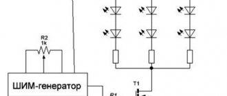
This driver can operate with voltages from 4.5 to 80 V, the maximum output current threshold is 2 A, which allows you to power a lamp using ultra-bright high-power LEDs. The level of electrical current passing through the LEDs is controlled by the RFB resistance. The implementation of PWM dimming with a frequency of 20 kHz allows you to smoothly change the electric current flowing through the LED.
The second version of the driver is based on the MP2489 chip. Its compact housing (QFN8 or TSOT23-5) makes it possible to place the driver in the MR16 socket used by halogen lamps, which allows replacing the latter with LED lamps. A typical MP2489 connection diagram is shown in the figure.
Driver based on MP2489
The above circuit allows you to connect two parallel LEDs, each with an operating current of 350 mA.
The latest version of the driver based on the MP3412 chip, which can be used in portable flashlights. A distinctive feature of this circuit is the ability to operate from an AA finger-type battery.
Driver for flashlight based on MP3412
Common connection errors
The most common mistakes when connecting LEDs:
- Choosing the wrong resistor value - if you choose too small a resistance, the LED may burn out. If the value is high, the diode will not shine at full strength.
- Connect directly to the power source without a current limiting resistor. The emitting component will immediately burn out.
- Parallel connection with one resistor for all diodes. Components will begin to fail because the operating current is different for each one.
- Connection in a series circuit of LEDs designed for different currents. In this case, some of the diodes will burn out, and some will shine dimmer.
- Connect directly to a 220 V network without protection.
Important! Making the described mistakes will entail negative consequences in the form of diode breakdown or self-injury.
How to power an LED from one AA battery
You can light an LED from one 1.5-volt AA battery using a simple circuit with a minimum of parts:
This circuit is essentially the simplest LED driver.
Required parts:
- A transformer, which is made on a ferrite ring by winding a wire with a cross-section of 0.25 mm, folded in half, approximately 25 turns;
- Bipolar H-channel transistor;
- A trim resistor is required to regulate the rated operating current of the converter;
- Schottke diode with low voltage drop;
- Capacitor.
Alternative connection type
Series-parallel connection of LEDs - found in floodlights and other powerful lamps operating on both direct and alternating voltage.
As you can see, the matrix is divided into branches, each of which has a current-limiting resistor. A specific copy is intended to replace the standard courtesy lamp in the car interior. If one diode fails, one circuit will stop lighting, and the remaining circuits will continue to glow.
If you can't decide whether to connect LEDs in series or parallel, there is an alternative option - a hybrid connection. At first glance, it is not clear what the point is.
The hybrid version takes advantage of the serial and parallel connection of LEDs. The circuit will work fully even if one of the elements in the circuit burns out, while at the same time the remaining elements will not experience overload. The voltage on each segment will be limited to the LED with the lowest drop.
To assemble the lamp correctly, and to ensure that the LEDs work for a long time and do not overheat, you need to decide how to connect the LEDs - in series or in parallel. You have become familiar with the strengths and weaknesses of each option. Thanks to the knowledge gained, you can repair an LED lamp or spotlight.
Use in everyday life
Most often, such circuits are found in backlit switches. A typical diagram of correct use is shown below:
Connecting an LED in a switch
Due to the low power of lighting devices, they do not have protective reverse diodes. The resistor is set to limit the forward current to 1 mA. This scheme for connecting an LED to a 220-volt network is not particularly effective in terms of the brightness of the glow, it is very dim, but it plays its role well - in a dark room the switch is visible. Here, the reverse voltage when the circuit contacts are opened is directed to a resistor; the presence of an LED or any other light bulb, as well as a power supply, also acts as an additional load. Thus, the LED is protected from reverse current breakdown.
About LED matrices
| Ready-made high-brightness LED matrices operating directly from 220 Volts are a convenient thing. A 20 Watt LED matrix shines like a 100 Watt incandescent lamp. |
Such matrices can be used both for street lighting, of course placing them in a protective housing, and for the home, where bright light is required. We should not forget that these matrices have an aluminum substrate and should be attached to metal parts of the case to dissipate heat.
Safety precautions
Briefly about the nuances of the connection, which is carried out in most homes - to ensure safety when working with an electrical circuit, it is often not enough to turn off just the switch. The fact is that it, as a rule, opens the phase, but due to the lack of grounding, a residual voltage remains at zero. If the grounding is incorrect, for example, people connect to a battery or water supply, there is a risk of getting voltage between the phase and ground. Turn off the power completely at the switch or meter at the entrance to the house or apartment, and make proper grounding if you do not have one.