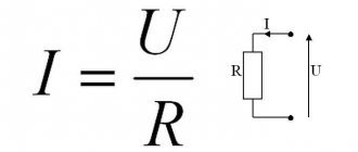
Ohm's law
- a physical law that defines the relationship between electrical quantities - voltage, resistance and current for conductors.
It was first discovered and described in 1826 by the German physicist Georg Ohm, who showed (using a galvanometer) the quantitative relationship between electromotive force, electric current and the properties of the conductor as a proportional relationship. Subsequently, the properties of a conductor that can resist electric current based on this dependence began to be called electrical resistance (Resistance), denoted in calculations and diagrams by the letter R
and measured in Ohms in honor of the discoverer.
The source of electrical energy itself also has internal resistance, which is usually denoted by the letter r
.
Ohm's law for a closed circuit
If an external circuit with resistance R is connected to the power source, current will flow in the circuit taking into account the internal resistance of the source:
I – Current strength in the circuit. Electromotive force (EMF) is the magnitude of the power source voltage independent of the external circuit (without load). Characterized by the potential energy of the source.
r – Internal resistance of the power supply. For electromotive force, the external resistance R and internal r are connected in series, which means the magnitude of the current in the circuit is determined by the value of the emf and the sum of the resistances: I =/(R+r) .
The voltage at the terminals of the external circuit will be determined based on the current and resistance R by the relationship that has already been discussed above: U = IR.
Voltage U, when connecting a load R, will always be less than the EMF by the value of the product I*r, which is called the voltage drop across the internal resistance of the power source. We encounter this phenomenon quite often when we see partially discharged batteries or accumulators in operation. As the discharge progresses, their internal resistance increases, therefore, the voltage drop inside the source increases, which means the external voltage U = – I*r decreases. The lower the current and internal resistance of the source, the closer in value its EMF and voltage at its terminals U.
If the current in the circuit is zero, therefore = U. The circuit is open, the emf of the source is equal to the voltage at its terminals. In cases where the internal resistance of the source can be neglected (r ≈ 0), the voltage at the source terminals will be equal to the EMF (≈ U) regardless of the external circuit resistance R. Such a power source is called a voltage source.
Third party force
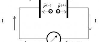
Nevertheless, current flows through the circuit; therefore, there is a force that “pulls” the charge through the source despite the resistance of the electric field of the terminals (Fig. 1).
Rice. 1. Third party force
This force is called a third party force; It is thanks to it that the current source functions. Third party force
has no relation to a stationary electric field - it is said to have a non-electric origin; in batteries, for example, it arises due to the occurrence of appropriate chemical reactions.
Let us denote by
the work of an external force to move a positive charge q inside a current source from the negative terminal to the positive. This work is positive, since the direction of the external force coincides with the direction of charge movement. The work of an external force is also called the work of a current source.
There is no external force in the external circuit, so the work done by the external force to move the charge in the external circuit is zero. Therefore, the work of an external force to move the charge
around the entire circuit comes down to the work of moving this charge only inside the current source. Thus, this is also the work of an external force to move charge throughout the circuit.
We see that the external force is non-potential - its work when moving a charge along a closed path is not zero. It is this non-potentiality that allows the electric current to circulate; a potential electric field, as we said earlier, cannot support a constant current.
Experience shows that work
directly proportional to the charge being moved. Therefore, the ratio no longer depends on the charge and is a quantitative characteristic of the current source. This relationship is denoted by: (1)
This quantity is called the electromotive force (EMF) of the current source. As you can see, EMF is measured in volts (V), so the name “electromotive force” is extremely unfortunate. But it has long been ingrained, so you have to come to terms with it.
When you see the inscription on the battery: “1.5 V”, then know that this is exactly the EMF. Is this value equal to the voltage created by the battery in the external circuit? It turns out not! Now we will understand why.
Ohm's law for alternating current
If there is inductance or capacitance in an AC circuit, its reactance must be taken into account. In this case, the entry for Ohm's Law will look like: I = U/Z
Here Z is the total (complex) resistance of the circuit - impedance. It includes active R and reactive X components. Reactance depends on the ratings of the reactive elements, on the frequency and shape of the current in the circuit. You can learn more about complex resistance on the impedance page.
Taking into account the phase shift φ created by reactive elements, Ohm's Law is usually written in complex form for sinusoidal alternating current.
Practical use
In most cases, the internal resistance of the current source is considered to be relatively small compared to that found in the electrical circuit. In this case, Ohm's law for a closed circuit is applied in an abbreviated formulation: I = U / R.
To better understand what physical processes occur in an electrical circuit, you need to consider the following:
- Processes are observed in the current source that lead to the formation of a potential difference at the terminals. When an electrical circuit is connected to them, current flows through it. It is generally accepted that it passes from a positive potential to a negative one.
- Current is the ordered movement of electrons. The substance contains a huge number of these particles, which move at high speed from negative to positive potential.
- The speed of electrons depends on the material of the conductor through which they pass, on its cross-section and length. If the latter is doubled, it will double the resistance.
Resistors are used in an electrical circuit in cases where a strictly defined resistance is required for the operation of the device. If the terminals of the current source, in simple words, are connected directly, then the resistance will be small and the current will be relatively large. On the one hand, high current in some cases can melt the wire; on the other hand, it leads to accelerated battery discharge.
In matter, the movement of electrons is not free. When moving, particles must overcome resistance, expending their energy to do so. The amount of resistance depends on the specific material. In conductors, electrons move relatively easily. No current can pass through insulators unless a voltage so high is applied that the situation creates a breakdown.
Semiconductors undergo more complex processes because they have a rigid crystal structure. In the presence of certain types of impurities, electron or hole conductivity can occur. Current can represent the movement of both electrons and holes.
A more accurate resistance characteristic can be obtained from the following formula:
Using resistivity, you can characterize the electrical properties of a certain substance. This value represents the resistance that a piece of wire made of this material has a length of 1 m and a cross-sectional area of 1 sq. m. mm.
Nonlinear elements and circuits
Ohm's law is not a fundamental law of nature and can be applied in limited cases, for example, for most conductors. It cannot be used to calculate voltage and current in semiconductor or vacuum devices, where this dependence is not proportional and can only be determined using the current-voltage characteristic (volt-ampere characteristic).
This category of elements includes all semiconductor devices (diodes, transistors, zener diodes, thyristors, varicaps, etc.) and vacuum tubes. Such elements and the circuits in which they are used are called nonlinear.
Electrical circuit
A source of electric current connected by wires to various electrical appliances and consumers of electrical energy forms an electrical circuit.
It is customary to depict an electrical circuit using diagrams in which the elements of the electrical circuit (resistances, current sources, switches, lamps, devices, etc.) are indicated with special icons.
The direction of current in a circuit is the direction from the positive pole of the current source to the negative pole. This rule was established in the 19th century. and has been observed ever since. The movement of real charges may not coincide with the conventional direction of the current. Thus, in metals, current carriers are negatively charged electrons, and they move from the negative pole to the positive one, that is, in the opposite direction. In electrolytes, the actual movement of charges may coincide with or be opposite to the direction of the current, depending on whether the ions are charge carriers - positive or negative.
The inclusion of elements in an electrical circuit can be serial or parallel.
Voltage, Current and Resistance
An electrical circuit is formed when a conductive path is created that allows electrical charge to travel continuously. This continuous movement of electric charge through the conductors of a circuit is called current, and is often spoken of as a “flow,” like the flow of liquid through a hollow pipe.
The force that causes charge carriers to “flow” through a circuit is called voltage. Voltage is a special measure of potential energy that is always relative between two points. When we talk about a certain amount of voltage present in a circuit, we are talking about the measurement of the potential energy to move charge carriers from one specific point in that circuit to another specific point. Without mentioning two specific points, the term "tension" has no meaning.
Current generally passes through conductors with some degree of friction or resistance to movement. This opposition to movement is more correctly called resistance. The amount of current in the circuit depends on the amount of voltage and the amount of resistance in the circuit that prevents the passage of current. Like voltage, resistance is a quantity measured between two points. For this reason, voltage and resistance values are often specified as "between" two points in a circuit.
How dangerous is electric current?
The answer to this question also depends on several factors. The chemical composition of a person's body has a significant impact on how electrical current affects a person. Some people are very sensitive to current and experience involuntary muscle contractions from static electricity shocks.
Others may receive a large shock of static electricity and barely feel it, much less experience a muscle spasm. Despite these differences, tests have developed rough guidelines that show that very little current is required to produce harmful effects (again, see the end of the chapter for the source of this data).
All current values are given in milliamps (a milliamp is 1/1000 of an ampere):
The effect of electric current on the human body
| Effect on the body | Men/women | D.C | AC, 60 Hz | AC, 10 kHz |
| Slight tingling of the hand | men | 1.0 mA | 0.4 mA | 7 mA |
| women | 0.6 mA | 0.3 mA | 5 mA | |
| Pain threshold | men | 5.2 mA | 1.1 mA | 12 mA |
| women | 3.5 mA | 0.7 mA | 8 mA | |
| Painful, but conscious muscle control is maintained | men | 62 mA | 9 mA | 55 mA |
| women | 41 mA | 6 mA | 37 mA | |
| It hurts, it’s impossible to let go of the wire | men | 76 mA | 16 mA | 75 mA |
| women | 51 mA | 10.5 mA | 50 mA | |
| Severe pain, difficulty breathing | men | 90 mA | 23 mA | 94 mA |
| women | 60 mA | 15 mA | 63 mA | |
| Possible cardiac fibrillation after 3 seconds of exposure | men and women | 500 mA | 100 mA |
"Hz" stands for the unit of measurement hertz. This is a measure of how quickly alternating current changes, known as frequency. Thus, the column of values labeled "Alternating Current, 60 Hz" refers to a current that changes at a rate of 60 cycles (1 cycle = a period of time when the current first flows in one direction and then in another direction) per second.
The last column, labeled "Alternating Current, 10 kHz," refers to alternating current, which completes ten thousand (10,000) cycles every second.
Keep in mind that these numbers are estimates as people with different body chemistry may respond differently. It has been suggested that for an alternating current flowing across the chest, as little as 17 mA is sufficient to cause fibrillation in a person under certain conditions. Most data regarding induced fibrillation come from animal testing. It is obviously impractical to perform ventricular fibrillation challenge tests in humans, so the available data are sketchy.
And in case you're wondering, I have no idea why women are more susceptible to electrical shock than men!
Let's say I put my hands on the terminals of an AC voltage source with a frequency of 60 Hz (60 cycles per second). What voltage would it take with clean, dry skin to produce 20 milliamps of current (enough that I couldn't let go of the voltage source)? To determine it, we can use Ohm's law:
\
Please keep in mind that from an electrical safety perspective this is the "ideal case" (clean, dry skin) and that this voltage value represents the amount needed to induce stupor. It would take much less tension to cause a painful blow! Also, keep in mind that the physiological effects of any particular amperage may vary significantly from person to person, and that these calculations are approximate.
After spritzing my fingers with water to simulate sweat, I was able to measure hand-to-hand resistance of just 17,000 ohms (17 kohms). Keep in mind that this only involves one finger of each hand touching the thin metal wire. By recalculating the voltage required to produce a current of 20 mA, we obtain the following value:
\
In this realistic condition, to induce 20 milliamps of current in the hand-to-hand path would require only 340 volts. However, it is still possible to receive a fatal blow from less voltage than this. Subject to a much lower body resistance value, increased by, for example, contact with a ring on the finger (a band of gold wrapped around the circumference of the finger is an excellent contact point for electric shock) or full contact with a large metal object such as a pipe or a metal tool handle, the body's resistance may drop to 1000 ohms (1 kohm), causing even lower voltages to pose a potential hazard.
\
Note that in this state, 20 volts is enough to induce a current of 20 milliamps through a person; enough to cause numbness. Remember, it has been suggested that current as low as 17 milliamps can cause ventricular (heart) fibrillation. With a hand-to-hand resistance of 1000 ohms, only 17 volts would be required to create this dangerous condition.
\
Seventeen volts is not much for electrical systems. Of course, this is a "worst case" scenario with 60Hz AC voltage and excellent body conductivity, but it shows how low voltage can pose a serious threat under certain conditions.
The conditions required to create 1000 ohm body resistance need not be as extreme as those presented (sweaty skin in contact with a gold ring). The body's resistance may decrease when tension is applied (especially if numbness causes the victim to tighten their grip on the conductor), so if tension is applied for a long time, the shock may increase after the initial contact.
What starts out as a mild shock (just enough to "freeze" the victim so that he cannot move) can develop into something serious enough to kill a person as his body's resistance decreases and the current increases accordingly.
Research has provided an approximate set of electrical resistance values for human contact points under various conditions (see the end of the chapter for the source of these data):
- finger contact with wire: from 40,000 Ohms to 1,000,000 Ohms dry, from 4,000 Ohms to 15,000 Ohms wet;
- holding the wire by hand: from 15,000 Ohms to 50,000 Ohms dry, from 3,000 Ohms to 5,000 Ohms wet;
- holding metal pliers by hand: from 5,000 Ohms to 10,000 Ohms in a dry state, from 1,000 Ohms to 3,000 Ohms in a wet state;
- palm contact: 3,000 ohms to 8,000 ohms dry, 1,000 ohms to 2,000 ohms wet;
- one-handed holding of 1.5-inch metal pipe: 1,000 ohms to 3,000 ohms dry, 500 ohms to 1,500 ohms wet;
- holding 1.5-inch metal pipe with two hands: 500 ohms to 1,500 ohms dry, 250 ohms to 750 ohms wet;
- hand immersed in conductive liquid: from 200 Ohm to 500 Ohm.
- the leg is immersed in a conductive liquid: from 100 Ohm to 300 Ohm.
Note the resistance values for the two conditions with 1.5-inch metal pipe. The resistance measured when holding the pipe with both hands is exactly half that when holding the pipe with one hand.
Figure 1 – Resistance when holding a metal pipe with one hand
When holding with two hands, the contact area with the body will be twice as large as with one hand. This is an important lesson: the electrical resistance between any objects in contact decreases as the contact area increases, all other things being equal. If you hold a pipe with both hands, the current will have two parallel paths along which it flows from the pipe into the person's body (or vice versa).
Figure 2 – Resistance when holding a metal pipe with both hands
As we will see in the next chapter, paths in a parallel circuit always result in less total resistance than any single path considered in isolation.
In industry, the conservative threshold for dangerous voltage is generally considered to be 30 volts. A cautious person should consider any voltage above 30 volts to be dangerous, without relying on normal body resistance to protect against shock. However, when working with electricity, it is still a good idea to keep your hands clean and dry and remove all metal jewelry.
Even at lower voltages, metal jewelry can be dangerous because it conducts enough current to burn the skin when it comes into contact between two points on a circuit. Metal rings in particular have been the cause of several finger burns due to point-to-point shorts in a low-voltage, high-current circuit.
Additionally, voltages below 30 can be dangerous if they are enough to cause an unpleasant sensation that could cause flinching and accidental contact with higher voltages or other hazards. I remember working on a car one hot summer day.
I was wearing shorts and my bare leg was touching the chrome bumper of the car as I tightened the battery terminals. When I touched the positive (non-grounded) side of the 12-volt battery with a metal wrench, I felt a tingling sensation where my foot touched the bumper. The combination of the tight contact with the metal and my sweaty skin allowed the shock to be felt at only 12 volts.
Fortunately, nothing bad happened, but if the engine had been running and the impact had been felt in my arm instead of my leg, I might have reflexively jerked my hand toward the spinning fan or dropped a metal wrench onto the battery terminals (creating more current through the wrench with a lot of sparks).
This illustrates another important lesson regarding electrical safety; Electrical current can be an indirect cause of injury by causing you to jerk or causing parts of your body to spasm.
The danger of electric current also depends on the path it takes through the human body. The current will affect all muscles in its path, and since the muscles of the heart and lungs (diaphragm) are probably the most important for survival, the current path through the chest is the most dangerous. Therefore, when electrical current flows along the hand-to-hand path, there is a greater chance of injury and death.
To avoid such situations, it is recommended to handle live circuits with only one hand. Of course, it is always safer to work on a circuit when it is disconnected, but this is not always practical or possible.
When working with one hand, the right hand is generally preferred for two reasons: most people are right-handed (which provides additional coordination when working), and the heart is located in the chest cavity to the left of center.
For lefties, this advice may not be the best. If such a person is not very dexterous with his right hand, he may expose himself to greater danger by using the hand with which he is least comfortable, even though the electrical current through the other hand may pose a greater danger to his heart. The relative danger between electrical shock through one hand versus the other is probably less than the danger of working with less than optimal coordination, so the choice of hand to work with is best left to the individual's discretion.
The best protection against live circuit shock is resistance, and resistance can be added to the body using insulated tools, gloves, shoes and other means. The current in a circuit is a function of the available voltage divided by the total resistance along the current path. As we'll look at in more detail later in this book, resistances are additive when they are composed so that current flows in only one path:
Figure 3 – Body resistance during direct contact
A person directly touches a voltage source: the current is limited only by the resistance of the human body.
\
Next we will see the equivalent circuit for a person wearing insulating gloves and boots:
Figure 4 – Contact resistance in insulating gloves and boots
The person is wearing insulating gloves and boots: the current is now limited by the impedance of the circuit.
\
Because in order to complete the circuit back to the voltage source, electrical current must pass through the boot and body and glove. And the total sum of these resistances opposes the passage of current to a greater extent than any of these resistances considered separately.
Safety is one of the reasons why electrical wires are usually covered with plastic or rubber insulation: to significantly increase the resistance between the conductor and anything that may come into contact with it.
Unfortunately, it would be prohibitively expensive to insulate power line conductors to ensure safety in the event of accidental contact. So in this case, safety is ensured by keeping these lines far enough out of reach that no one can accidentally touch them.
Coulomb and electric charge
One of the basic units of electrical measurement that is often taught early in electronics courses but not often used subsequently is the coulomb, a unit of electrical charge proportional to the number of electrons in an unbalanced state. One coulomb of charge corresponds to 6,250,000,000,000,000,000 electrons. The symbol for the amount of electric charge is the capital letter "Q", and the unit of coulombs is denoted "C". The unit of current, ampere, is equal to 1 coulomb of charge passing through a given point in a circuit in 1 second. In this sense, current is the speed at which an electric charge moves through a conductor.
As stated earlier, voltage is a measure of the potential energy per unit of charge available to stimulate the flow of current from one point to another. Before we can define exactly what a "volt" is, we must understand how to measure this quantity, which we call "potential energy."
The common metric unit for measuring energy of any kind is the joule, which is equal to the amount of work done by a force of 1 newton when moving 1 meter (in the same direction). In these scientific terms, 1 volt is equal to 1 joule of electrical potential energy per (divided by) 1 coulomb of charge. Thus, a 9-volt battery releases 9 joules of energy for every coulomb of charge passing through the circuit.
These units and symbols for electrical quantities will become very important when we begin to explore the relationships between them in circuits.
Units of measurement: volts, amperes and ohms
To be able to make meaningful statements about these quantities in circuits, we need to be able to describe their quantities in the same way that we might quantify mass, temperature, volume, length, or any other physical quantity. For mass we can use the units "kilogram" or "gram". For temperature, we can use Fahrenheit or Celsius. The table below shows standard units of measurement for electrical current, voltage and resistance:
Units of measurement of current, voltage, resistance ValueSymbolUnit of measurementAbbreviation of the unit of measurement
| Current | I | Ampere | A |
| Voltage | V | Volt | IN |
| Resistance | R | Ohm | Ohm |
The "symbol" assigned to each quantity is the standard letter of the Latin alphabet used to represent that quantity in formulas. Such standardized letters are common in all physical and engineering disciplines and are recognized throughout the world. The "unit abbreviation" for each quantity is the alphabetical character(s) used as an abbreviation for a specific unit of measurement.
Each unit of measurement is named after a famous electrical experimenter: the ampere after the Frenchman Andre M. Ampere, the volt after the Italian Alessandro Volta, and the ohm after the German Georg Simon Ohm.
The mathematical symbol for each quantity also has a meaning. "R" for resistance and "V" for voltage are self-explanatory ("Resistance" and "Voltage", respectively), while "I" for current seems a little strange. The letter "I" is supposed to represent "Intensity" (charge flow). Based on the research I've been able to do, there seems to be some disagreement about the meaning of the "I" word. Another voltage symbol, "E", stands for "Electromotive force". The symbols "E" and "V" are for the most part interchangeable, although in some texts "E" is reserved for voltage at a source (such as a battery or generator) and "V" for voltage at any other element.
All of these symbols are expressed in capital letters, except when a quantity (especially voltage or current) is described in terms of a short period of time (called "instantaneous" values). For example, a battery voltage that is stable over a long period of time will be symbolized by a capital letter "E", whereas the peak voltage when a lightning strike occurs just as it hits the power line will most likely be symbolized by a lowercase letter "e". (or a lowercase "v") to mark the value as existing at one point in time. The same lowercase convention holds true for current: a lowercase "i" represents current at some point in time. However, most measurements in DC circuits that are stable over time will be indicated by capital letters.
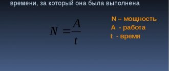
Ohm's law formula
Ohm's main discovery was that the amount of electric current flowing through a metal conductor in a circuit, at any given temperature, is directly proportional to the voltage applied to it. Ohm expressed his discovery in the form of a simple equation describing the relationship between voltage, current and resistance:
[E=IR]
In this algebraic expression, voltage (E) equals current (I) times resistance (R). Using algebra, we can transform this equation into two other variants, solving it for I and R respectively:
Electrical circuit efficiency
It is not difficult to understand why the resistor
called the payload. Imagine it's a light bulb. The heat generated by the light bulb is useful, since thanks to this heat the light bulb fulfills its purpose - giving light.
The amount of heat released by the payload
for time, let's denote .
If the current in the circuit is equal to
, That
A certain amount of heat is also released at the current source:
The total amount of heat released in the circuit is equal to:
The efficiency of an electrical circuit is the ratio of useful heat to total heat:
The efficiency of the circuit is equal to unity only if the current source is ideal
.
Analyzing simple circuits using Ohm's law
Let's see how these formulas work to help us analyze simple circuits:
Figure 1 – Example of a simple circuit
In the above circuit, there is only one voltage source (the battery on the left) and only one current resistance source (the lamp on the right). This makes it very easy to apply Ohm's law. If we know the values of any two of the three quantities (voltage, current, and resistance) in this circuit, we can use Ohm's law to determine the third.
Rules for using the calculator
In everyday life, we are usually interested in four interrelated characteristics of electricity:
- voltage;
- current;
- resistance;
- or power.
If you know two quantities included in Ohm’s law (U, R, I), then enter them in the appropriate lines, and the remaining parameter and power will be calculated automatically.
Be careful to avoid mistakes.
All values must be filled out in the same dimension : amperes, volts, ohms, watts without using fractional or multiplicity symbols.
A visual table will help you navigate to them.
Ohm's Law Triangle Method
Ohm's Law is a very simple and useful tool for analyzing electrical circuits. It is used so often in the study of electricity and electronics that the student must memorize it. If you are not very good at working with formulas, then for memorizing it there is a simple trick that helps you use it for any quantity, knowing the other two. First, arrange the letters E, I and R in a triangle like this:
Figure 5 – Ohm's law triangle
If you know E and I and want to define R, just remove R from the picture and see what's left:
Figure 6 - Ohm's law for determining R
If you know E and R and want to define I, remove I and see what's left:
Figure 7 - Ohm's law for determining I
Finally, if you know I and R and want to define E, remove E and see what's left:
Figure 8 - Ohm's law for determining E
Ultimately, you'll have to learn how to work with formulas to study electricity and electronics seriously, but this tip can make it easier to remember your first calculations. If you're comfortable working with formulas, all you have to do is commit E = IR to memory and retrieve the other two formulas when you need them!
What does parallel and serial connection give?
Theoretical knowledge is good, but how to apply it in practice? Elements of any type can be connected in parallel or in series. But we considered only the simplest formulas describing linear elements. Linear elements are resistances, which are also called “resistors”. So here's how you can use what you've learned:
- If there is no large resistor available, but there are several smaller ones, the required resistance can be obtained by connecting several resistors in series. As you can see, this is a useful technique.
- To extend the life of the batteries, they can be connected in parallel. In this case, according to Ohm’s law, the voltage will remain the same (you can verify this by measuring the voltage with a multimeter). And the “lifetime” of a dual battery will be significantly longer than that of two elements that replace each other. Just note: only power supplies with the same potential can be connected in parallel. That is, you cannot connect dead and new batteries. If you do connect, the battery that has a higher charge will tend to charge the less charged one. As a result, their total charge will drop to a low value.
Practical application of Ohm's law: you can create power supplies with the desired voltage and current
In general, these are the most common uses for these compounds.
Application in practice
When you need to work with an electrical circuit, it is important to know the voltage, current, resistance in the entire circuit or in individual sections. If two of these quantities are known, then using Georg Ohm's law you can find out the third without making direct measurements.
Sometimes it is necessary to use Ohm's law for a non-uniform section of a circuit. In this case, it is divided into separate zones and calculations are first carried out for them.
Since thermal or chemical effects depend on electrical parameters, applying Ohm's law you can calculate the possible effect. In particular, knowledge of such features allows you to avoid the destructive effect of too high a current.
Ohm's law can be expressed in integral and differential forms. In the first case, we are talking about the traditional formulation, and its expression in differential form takes into account specific conductivity - the reciprocal of resistivity.
In conclusion, it should be said that resistance measurement is carried out using a special device - an ohmmeter. But this is impossible to do in a working circuit. You can determine the resistance value without disconnecting the circuit by calculation using Ohm's law and by first measuring the voltage and current in the desired section of the circuit.
Parallel and serial connection
In electrics, elements are connected either in series - one after the other, or in parallel - this is when several inputs are connected to one point, and outputs from the same elements are connected to another.
Ohm's law for parallel and series connections
Parallel connection
A parallel connection is when the beginnings of the conductors/elements converge at one point, and their ends are connected at another. We will try to explain the laws that are valid for compounds of this type. Let's start with the current. A current of some magnitude is supplied to the point of connection of the elements. It separates, flowing through all conductors. From here we conclude that the total current in the section is equal to the sum of the current on each of the elements: I = I1 + I2 + I3.
Now regarding the voltage. If voltage is the work done to move a charge, then the work required to move one charge will be the same on any element. That is, the voltage on each parallel-connected element will be the same. U = U1=U2=U3. It’s not as fun and visual as in the case of explaining Ohm’s law for a section of a circuit, but you can understand it.
For resistance, everything is a little more complicated. Let's introduce the concept of conductivity. This is a characteristic that shows how easy or difficult it is for a charge to pass through this conductor. It is clear that the lower the resistance, the easier it will be for current to pass. Therefore, conductivity - G - is calculated as the reciprocal of resistance. In the formula it looks like this: G = 1/R.
Laws for parallel connection
Why did we talk about conductivity? Because the total conductivity of a section with a parallel connection of elements is equal to the sum of the conductivity for each of the sections. G = G1 + G2 + G3 - easy to understand. How easy it is for current to cross this node of parallel elements depends on the conductivity of each element. So it turns out that they need to be folded.
Now we can move on to resistance. Since conductivity is the reciprocal of resistance, we can obtain the following formula: 1/R = 1/R1 + 1/R2 + 1/R3.
Current source resistance
Ohm's law for a complete electrical circuit and formulas for calculating its parameters characterize not only the current passing through the circuit, but also that which exists inside the current source. Ohm's law for a section of a circuit does not take into account the presence of this quantity.
The battery is responsible for the movement of electrons from the positive terminal to the negative terminal. Through an electrical circuit they are constantly moving in the opposite direction. The decrease in their number on the negative terminal and the excess on the positive terminal are constantly compensated by processes occurring inside the device.
This movement of electrons is also an electric current. In this case, the particles have to overcome the internal resistance of the current source. As the temperature increases, the resistance may change, the nature of the change depends on the specific material.
Practical use
Actually, this law can be applied to any part of the chain. An example is shown in the figure.
We apply the law to any part of the chain.
Using such a plan, you can calculate all the necessary characteristics for an unbranched section. Let's look at more detailed examples.
Finding the current strength
Let's now consider a more specific example, let's say there is a need to find out the current flowing through an incandescent lamp. Conditions:
- Voltage – 220 V;
- R filament – 500 Ohm.
The solution to the problem will look like this: 220V/500Ohm=0.44 A.
Let's consider another problem with the following conditions:
- R=0.2 MOhm;
- U=400 V.
In this case, first of all, you will need to perform the conversion: 0.2 MOhm = 200000 Ohm, after which you can begin to solve: 400 V/200000 Ohm = 0.002 A (2 mA). Calculating voltage To solve, we will also use Ohm's law. So the task:
- R=20 kOhm;
- I=10 mA.
Let's transform the source data:
- 20 kOhm = 20000 Ohm;
- 10 mA=0.01 A.
Solution: 20000 Ohm x 0.01 A = 200 V.
Don't forget to convert the values, since quite often the current can be indicated in milliamps.
Resistance
Despite the fact that the general form of the method for calculating the parameter “R” resembles finding the value “I”, there are fundamental differences between these options. If the current can vary depending on two other parameters, then R (in practice) has a constant value. That is, at its core, it is represented as an unchanging constant.
If the same current (I) passes through two different sections, while the applied voltage (U) differs, then, based on the law we are considering, we can confidently say that where the low voltage “R” will be the smallest. Let's consider the case when there are different currents and the same voltage in unconnected areas. According to Ohm's law, a large current will be characteristic of a small parameter "R".
Let's look at a few examples
Let's say there is a circuit to which the voltage U=50 V is applied, and the consumed current I=100 mA. To find the missing parameter, you should use 50 V / 0.1 A (100 mA), in the end the solution will be 500 Ohms.
The current-voltage characteristic allows you to clearly demonstrate the proportional (linear) dependence of the law. The figure below is a graph for a section with a resistance equal to one ohm (almost like a mathematical representation of Ohm's law).
Image of the current-voltage characteristic, where R=1 Ohm
Illustration of current-voltage characteristics
The vertical axis of the graph displays the current I (A), the horizontal axis displays the voltage U(V). The graph itself is presented in the form of a straight line, which clearly displays the dependence on the resistance, which remains unchanged. For example, at 12 V and 12 A, “R” will be equal to one ohm (12 V/12 A).
Please note that the current-voltage characteristic shown only shows positive values. This indicates that the circuit is designed to allow current to flow in one direction. Where the opposite direction is allowed, the graph will continue to negative values.
Note that equipment whose current-voltage characteristic is displayed as a straight line is called linear. The same term is used to refer to other parameters.
In addition to linear equipment, there are various devices whose “R” parameter can change depending on the current or applied voltage. In this case, Ohm's law cannot be used to calculate the dependence. Equipment of this type is called nonlinear; accordingly, its current-voltage characteristics will not be displayed as straight lines.
Conductor resistivity table
Electrical resistance (ρ) of 1 meter of wire, cross section 1 mm², at a temperature of 20 C°:
| Conductor material | Specific resistance ρ, Ohm |
| Silver | 0.015 |
| Copper | 0.0175 |
| Gold | 0.023 |
| Brass | 0,025. 0,108 |
| Chromium | 0,027 |
| Aluminum | 0.028 |
| Sodium | 0.047 |
| Iridium | 0.0474 |
| Tungsten | 0.05 |
| Zinc | 0.054 |
| Molybdenum | 0.059 |
| Nickel | 0.087 |
| Bronze | 0,095. 0,1 |
| Iron | 0.1 |
| Steel | 0,103. 0,137 |
| Tin | 0.12 |
| Lead | 0.22 |
| Nickelin (an alloy of copper, nickel and zinc) | 0.42 |
| Manganin (alloy of copper, nickel and manganese) | 0,43. 0,51 |
| Constantan (alloy of copper, nickel and aluminum) | 0,44-0,52 |
| Copel (copper-nickel alloy with 43% nickel and 0.5% manganese) | 0.5 |
| Titanium | 0.6 |
| Mercury | 0.94 |
| Chromel (chrome 8.7 - 10%; nickel 89 - 91%; silicon, copper, manganese, cobalt - impurities) | 1.01 |
| Nichrome (an alloy of nickel, chromium, iron and manganese) | 1,05. 1,4 |
| Fechral | 1,15. 1,35 |
| Bismuth | 1.2 |
| Chromal (Alloy 4.5 - 6% aluminum, 17 - 30% chromium, iron) | 1,3. 1,5 |
The conductor resistance is determined by the formula r = (ρ × l) / S, where:
- r — conductor resistance, Ohm.
- ρ —conductor resistivity, Ohm.
- l is the length of the conductor, m.
- S —conductor cross-section, mm².