Engineers and simply enthusiasts in the world of electronics quite often need to carry out some measurements, one of which is power measurement. Therefore, in this article we will look at creating a homemade wattmeter based on an Arduino board, with which you can measure voltage, current and power of an electrical signal.
Some may say why make such a device if you can now buy it relatively inexpensively. Yes it is. But surely some of you want to make a more advanced wattmeter than the one you can just buy. Using an Arduino board to create a wattmeter, we can display measured values on a computer screen, plot them, save their values to an SD card when their values are within specified intervals, and much more.
Required Components
- Arduino Nano board (buy on AliExpress).
- Operational amplifier LM358 (buy on AliExpress).
- Voltage regulator LM7805 (buy on AliExpress).
- LCD display 16x2 (buy on AliExpress).
- Shunt resistor 0.22 ohm 2Watt (buy on AliExpress).
- Trimmer potentiometer 10 kOhm (Trimmer pot) (buy on AliExpress).
- Resistors 10 kOhm, 20 kOhm, 2.2 kOhm, 1 kOhm (buy on AliExpress).
- Capacitors 0.1 uF (buy on AliExpress).
- Test load.
- Perforated or breadboard.
What is AREF?
When your Arduino takes an analog reading, it compares the voltage measured at the analog pin it is using with what is called a reference voltage. In normal analog reading use, the reference voltage is the operating voltage of the board.
For more popular Arduino boards such as Uno, Mega, Duemilanove and Leonardo/Yún boards, the operating voltage is 5V. If you have an Arduino Due board, the operating voltage is 3.3V. So, if you have a 5V reference voltage, each block returned by analogRead() is valued at 0.00488V. (This is calculated by dividing 1024 by 5V). What if we want to measure voltages between 0 and 2 or 0 and 4.6? How does the ADC know what is 100% of our voltage range?
And this is the reason the AREF pin exists. AREF stands for Analog Reference. This allows us to feed the Arduino a reference voltage from an external power supply. For example, if we wanted to measure voltages with a maximum range of 3.3V, we would supply a nice smooth 3.3V to the AREF pin from, for example, a voltage regulator IC.
Then each ADC step will represent about 3.22 millivolts (divide 1024 by 3.3V). Note that the lowest reference voltage you can have is 1.1V. There are two forms of AREF - internal and external, so let's check them out.
Circuit operation
The wattmeter circuit based on the Arduino board is shown in the following figure.
To make it easier to understand, the diagram is divided into 2 parts. The upper part of the circuit is its measuring part, and the lower part of the circuit is used to carry out calculations and display their results. The connection points of both parts of the circuit are indicated using labels.
The circuit is designed to operate with voltage in the range of 0-24V with a current of 0-1A - these parameters are specially selected to work with Solar PV (solar photovoltaic system). But if you understand the principles of operation of this circuit, you can easily expand the ranges of its operation to the ones you need. The fundamental operating principle of this circuit is to measure the voltage and current in the load in order to then calculate the power consumed by the load. The values of all measured parameters will be displayed on the 16x2 LCD screen.
Next, let's look at the individual operation of small elements of the presented circuit in order to better understand its operation.
Measuring unit
The measurement block of the circuit consists of a voltage divider with two resistors to measure the voltage value and a shunt resistor with a non-inverted op-amp to measure the current. The voltage divider is shown in the following figure:
The input voltage in this circuit is designated Vcc. As we said earlier, the circuit is designed to measure voltages from 0V to 24V. But the Arduino board cannot measure such large voltages - it can only measure voltages in the range of 0-5V. Accordingly, we must convert the measured voltage in the range of 0-24V to the range of 0-5V. This conversion is precisely carried out using the presented voltage divider. Accordingly, the resistor values in the circuit of this divider (10 kOhm and 2.2 kOhm) are precisely selected in such a way as to convert the 0-24V range to the 0-5V range. If you need to change the range of voltages measured by the circuit, you just need to change the values of the resistors in the presented voltage divider circuit. The voltage value at the output of the voltage divider can be calculated using the well-known formula:
Vout = (Vin × R2) / (R1 + R2)
The voltage converted to the 0-5V range from the midpoint of the voltage divider is indicated in our diagram with the Voltage label. Subsequently, this converted voltage value is supplied to the analog input of the Arduino board.
Next we must measure the current through the load (LOAD). Since microcontrollers can only read analog voltage values, we need to convert the current value to a voltage value. This can be done by adding a shunt resistor - according to Ohm's law, the voltage drop across it will be proportional to the current flowing through it. Since the voltage drop across the shunt resistor will be very small, we will use an op-amp to amplify it. The diagram for carrying out this process is shown in the following figure:
The resistance value of the shunt resistor (SR1) in our case is 0.22 Ohm. As stated earlier, our circuit is designed to measure current in the 0-1A range, so according to Ohm's Law, at a maximum current through a 1A load, the voltage drop across our shunt resistor will be approximately 0.2V. This voltage is too low to be read by the microcontroller, so we use an op-amp in non-inverted amplification mode to amplify this voltage to a value that can be comfortably read by the Arduino board.
The op amp in non-inverted mode is shown in the above diagram. The amplifier is designed in such a way that its gain is 21, resulting in 0.2*21 = 4.2V. The formula for calculating the gain of the presented operational amplifier is as follows:
Gain = Vout / Vin = 1 + (Rf / Rin)
If you need to change the range of current values measured by the circuit, you need to change the resistance value of the shunt resistor, as well as the resistance values of the resistors that affect the gain of the operational amplifier.
In our case, the value of resistor Rf is 20 kΩ and the value of resistor Rin is 1 kΩ, which provides a gain of 21 for the op-amp. Next, the voltage from the output of the operational amplifier is supplied to an RC filter consisting of a 1 kOhm resistor and a 0.1 μF capacitor. This filter is designed to filter out unwanted noise. Next, the filtered voltage is supplied to the analog input of the Arduino board.
And finally, the last component that we need to consider in the measurement unit of our circuit is the voltage regulator. Since we are supplying a variable voltage to the input of the circuit, we need a stabilized voltage of +5V to power the Arduino board and operational amplifier. This regulated (stabilized) voltage in our circuit is provided by the 7805 voltage regulator. A capacitor is added at the output of the regulator circuit to filter out noise.
Block of calculations and information display
In the measurement block, we designed a circuit to convert the measured values and currents into a voltage range of 0-5V, which are directly fed to the analog inputs of the Arduino. In the same part of the circuit, we connect these voltage wires to the Arduino board, and also connect an alphanumeric LCD display to the Arduino board to display the measurement results. The diagram of this block is shown in the following figure.
As you can see from the diagram, the voltage pin is connected to analog pin A3, and the current pin is connected to analog pin A4 of the Arduino board. The LCD display is powered by +5V from the 7805 regulator and connected to the digital pins of the Arduino board in 4-bit mode. We also use a 10k ohm potentiometer connected to the Con pin of the LCD to adjust its contrast.
Arduino ammeter for smart home
If you are very worried about the consumption of electrical energy and really want to figure out the culprit, this is your day. We will assemble a current sensor and write simple logic to process the input values to convert the values into kilowatts/hour.
For assembly I used an Arduino nano board (no one is stopping you from using the same code for ESP or STM boards), LCD screen shield, 56 Ohm resistor, 100 kOhm resistors, 10 uF capacitor, CT current sensor - Talema AC103 (with nominal measurement 30A and maximum 75A).
What is a current sensor?
The current sensor is a magnetic circuit with a gap and a compensation winding, as well as a built-in Hall sensor and control board. The Hall sensor is placed in the gap of the magnetic circuit and reacts to the magnetic field created by the coil. The stronger the magnetic field strength, the stronger the Hall sensor produces a signal, which is amplified by the control board. Current sensors are available for measuring alternating current and direct current. Ours - CT-Talema AC103 - for variable.
Let's assemble our device according to the diagram:
The LCD shield already has pins for connecting our analog ports for signal measurement - and this is convenient. The only phase input cable needs to be passed through the current sensor because Often not all the voltage reaches the neutral wire - some may go through grounding.
Don't forget that we need to calibrate the load resistor R3. Calculation formula R = V / I - R = 2.5 / 0.042 = 59.5 Ohms where 2.5 is the reference voltage on the board, and 42mA is the board consumption. Therefore, we accept the closest resistor in nominal value - 56 Ohms. To divide the main supply voltage to the reference 5/2, you will need to install two identical resistors R1 and R2.
All that remains is to upload the example code to Arduino:
//Michael Klements //The DIY Life //27 October 2014 #include int currentPin = 1; //Assign CT input to pin 1 double kilos = 0; int peakPower = 0; LiquidCrystal lcd(8, 9, 4, 5, 6, 7); //Assign LCD screen pins, as per LCD shield requirements void setup() { lcd.begin(16,2); // columns, rows. use 16.2 for a 16×2 LCD, etc. lcd.clear(); lcd.setCursor(0,0); // set cursor to column 0, row 0 (the first row) lcd.print("Running"); } void loop() { int current = 0; int maxCurrent = 0; int minCurrent = 1000; for (int i=0 ; i<=200 ; i++) //Monitors and logs the current input for 200 cycles to determine max and min current { current = analogRead(currentPin); //Reads current input and records maximum and minimum current if(current >= maxCurrent) maxCurrent = current; else if(current <= minCurrent) minCurrent = current; } if (maxCurrent <= 517) { maxCurrent = 516; } double RMSCurrent = ((maxCurrent - 516)*0.707)/11.8337; //Calculates RMS current based on maximum value int RMSPower = 220*RMSCurrent; //Calculates RMS Power Assuming Voltage 220VAC, change to 110VAC accordingly if (RMSPower > peakPower) { peakPower = RMSPower; } kilos = kilos + (RMSPower * (2.05/60/60/1000)); //Calculate kilowatt hours used delay (2000); lcd.clear(); lcd.setCursor(0,0); // Displays all current data lcd.print(RMSCurrent); lcd.print("A"); lcd.setCursor(10,0); lcd.print(RMSPower); lcd.print("W"); lcd.setCursor(0,1); lcd.print(kilos); lcd.print("kWh"); lcd.setCursor(10,1); lcd.print(peakPower); lcd.print("W"); }
The final touch of our installation will be calibration. It is best to perform it with a reference load of known power turned on. Powerful incandescent lamps are well suited for this. Let's take a 100 Watt lamp. We turn on the board and calculate the correction factor: Double RMSCurrent = ((maxCurrent - 516) * 0.707) /11.8337 where 11.8337 is the selected coefficient to compensate for differences in measurements.
How to improve measurement accuracy
This approach to measuring current and voltage works quite well, but has the disadvantage that the relationship between the measured voltage at the ADC output and the actual voltage value is not completely linear, so simple multiplication in the program cannot provide very high accuracy measurements.
To increase the measurement accuracy, we can build a set of measured values from the ADC output with a set of corresponding real voltage values, then use these two sets to build a graph and, based on it, calculate the required coefficient for multiplication using the linear regression method.
Finally, when we know the current and voltage values, we can calculate the power using the well-known formula P=V*I and then display all these three values on the LCD screen.
Why does analogRead() return a value between 0 and 1023?
This is due to the resolution of the ADC. Resolution (for the purposes of this article) is the degree to which something can be represented numerically. The higher the resolution, the higher the accuracy with which something can be represented. We measure resolution in terms of the number of bits of resolution.
For example, 1-bit resolution will only allow two (two to the power of one) values - zero and one. 2-bit resolution would allow for four (two to the power of two) values—zero, one, two, and three. If we try to measure a five-volt range with two-bit resolution, and the measured voltage is four volts, our ADC will return a numerical value of 3—with a four-volt drop between 3.75 and 5V. It's easier to imagine this with the image above.
Thus, in our example, an ADC with 2-bit resolution can only represent a voltage with four possible resulting values. If the input voltage falls between 0 and 1.25, the ADC returns a 0; if the voltage drops between 1.25 and 2.5, the ADC returns the numerical value 1. And so on. With our Arduino's ADC range being 0 to 1023 - we have 1024 possible values - or 2 to 10, so our Arduinos have ADCs with 10-bit resolution.
Testing the project's operation
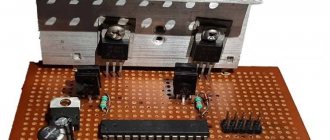
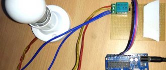
To assemble the circuit, we used a perforated board as shown in the figure below. We used a Phoenix clamp terminal to connect the load and a normal DC barrel Jack to then connect to the voltage source.
Once the hardware of the project is ready, upload the program code to the Arduino Nano board. Use the potentiometer to adjust the contrast of the LCD display. To test the operation of the circuit, connect the load and power source. The power supply voltage must be at least 6V since the Arduino board requires a voltage of +5V for its operation. If the circuit is working as expected, you should see the measured voltage and current values, as well as the calculated power value, on the LCD screen. These processes are shown in more detail in the video at the end of the article.
To calibrate our wattmeter, you can use some “factory” wattmeter. Using the capabilities of the Arduino platform, you can significantly improve the functionality of this project - add a data logger to an SD card, plotting, notifications about some situations (for example, when voltage and current values go beyond the permissible values) and much more.
On our website you can also see similar projects:
- ohmmeter on Arduino;
- ammeter on Arduino;
- voltmeter on Arduino.
Internal AREF
The microcontrollers on our Arduino boards can also generate an internal 1.1V reference voltage, and we can use this to operate AREF. Just use the line:
analogReference(INTERNAL);
For Arduino Mega boards in void setup() use:
analogReference(INTERNAL1V1);
For Arduino Mega there is also a reference voltage of 2.56V, which is activated like this:
analogReference(INTERNAL2V56);
Finally, before settling on the results obtained from your AREF pin, always calibrate the readings against a known good multimeter. The AREF function gives you more flexibility when measuring analog signals.
Specifications
Let's look at the characteristics of the ACS712 board in more detail, naturally dividing them depending on the capabilities of the various models:
- Power supply - 5V;
- current consumption - 0.11A;
- busbar resistance - up to 1.2 mOhm;
- type of measured characteristic - direct or alternating current;
- operating temperature – from –40 to +85°С;
- additional indicators - there is an LED for current supply to power the device;
- dimensions (on average) - 31 x 13 mm;
- the critical current leading to breakdown of the device is 50A.
Sensitivity:
| Model | mV/A |
| ACS712 5A | 185 |
| ACS712 20A | 100 |
| ACS712 30A | 66 |
| ACS713 20A | 185 |
| ACS713 30A | 133 |
Internal electronic circuit of the sensor:
Checking the voltmeter
Checking the voltmeter consists of comparing the readings of the voltmeter on the Arduino with a working voltmeter (multimeter). If the values are different, you need to check the voltage on the Arduino 5V and GND pins. The voltage may vary slightly from 5 volts. For example, 4.95 V. Then in the formula temp = (analogvalue * 5.0) / 1024.0 you need to replace the value 5 with 4.95. And you also need to check the exact resistance of resistors R1 and R2 and enter your values in the lines float r1=100000.0 and float r2=10000.0. After such verification, we will receive an accurate voltmeter on Arduino. This device is capable of measuring voltage up to hundredths of volts. And finally, I would like to warn you. It is not recommended to use this voltmeter to measure 55 volts. This is the maximum limit. If there is a slight jump in the measured voltage, the microcontroller will fail. It is necessary to provide some reserve for unforeseen situations. And limit the range of measured voltage to 45 volts.