It's no secret that LED lamps periodically burn out, despite long warranty periods. Such lamps have certain parameters that require mandatory stabilization. This is the current strength in the lamp itself and the voltage drop in the supply network. To solve this problem, a current stabilizer for LEDs is used. But not all stabilizers can solve the problem. Therefore, in some cases it is recommended to make a stabilizer yourself. Before starting this process, you should understand the purpose, structure and operating principle of the stabilizer in order to avoid mistakes when assembling the circuit.
Design and operating principle
The stabilizer ensures constant current when it deviates.
The stabilizer ensures constant operating current of LED diodes when it deviates from the norm. It prevents overheating and burnout of LEDs, maintains constant flow during voltage surges or battery discharge.
The simplest device consists of a transformer, a rectifier bridge connected to resistors and capacitors. The action of the stabilizer is based on the following principles:
- supplying current to the transformer and changing its limiting frequency to the mains frequency - 50 Hz;
- voltage adjustment to increase and decrease with subsequent frequency equalization to 30 Hz.
The conversion process also uses high-voltage rectifiers. They determine the polarity. Stabilization of the electric current is carried out using capacitors. Resistors are used to reduce interference.
Number of phases
Voltage stabilizers are single-phase or three-phase. The first are installed in rooms equipped with a single-phase network, the second - when connecting the house to an electrical network with a voltage of 380 V. A single-phase device is also suitable for a three-phase network, if you comply with the condition of installing a separate device for each phase.
When choosing a stabilizer separately for a chandelier, you can choose a single-phase one. In this case, it is enough to know the network connection diagram and power indicators: peak and nominal (data is available in the device passport).
Types of current stabilizers
The LED lights up when the current threshold value is reached. For low-power devices this figure is 20 mA, for high-bright devices - from 350 mA. The spread of the threshold voltage explains the presence of different types of stabilizers.
Resistor stabilizers
Stabilizer KREN
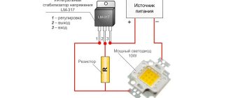
For an adjustable stabilizer of current parameters for low-power LEDs, the KREN circuit is used. It provides for the presence of elements KR142EN12 or LM317. The equalization process is carried out at a current of 1.5 A and an input voltage of 40 V. Under normal thermal conditions, the resistors dissipate up to 10 tons of power. Their own power consumption is about 8 mA.
The LM317 node maintains a constant voltage value across the main resistor, regulated by a trimmer. The main, or current-distributing element can stabilize the current passed through it. For this reason, ROLL stabilizers are used to charge batteries.
The 8 mA value does not change even with fluctuations in input current and voltage.
Transistor devices
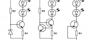
Transistor voltage stabilizer circuit
The transistor regulator involves the use of one or two elements. Despite the simplicity of the circuit, when voltage fluctuations occur, there is not always a stable load current. As it increases, the resistor voltage on one transistor increases to 0.5-0.6 V. After this, the second transistor starts working. At the moment of its opening, the first element closes, and the strength and magnitude of the current passing through it decreases.
The second transistor must be bipolar.
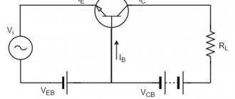
Two circuits for transistors of different conductivities, in which the zener diodes are replaced by two conventional diodes VD1, VD2
To implement the circuit with replacing zener diodes with diodes, the following are used:
- diodes VD1 and VD2;
- resistor R1;
- resistor R2.
The current flow through the LED element is set by resistor R2. To reach the linear section of the I-V characteristics of diodes tied to the current of the base transistor, resistor R1 is used. In order for the transistor to remain stable, the supply voltage should not be less than the total voltage of the diodes + 2-2.5 V.
To obtain a current of 30 mA, 12 V is supplied in a straight line through 3 series-connected diodes with a voltage of 3.1 V. The resistor resistance should be 20 Ohms with a dissipation power of 18 mW.
The circuit normalizes the operating mode of the elements and reduces current ripples.
Circuit with Soviet transistors. The permissible voltage of the Soviet KT940 or KT969 is up to 300 V, which is suitable if the light source is a powerful SMD element. The current parameters are set by a resistor. The zener diode voltage is 5.1 V, and the power is 0.5 V.
The disadvantage of the circuit is the voltage drop when the current increases. This can be eliminated by replacing the bipolar transistor with a MOSFET with low resistance parameters. The powerful diode is replaced by an IRF7210 12 A element or an IRLML6402 3.7 A element.
Current stabilizers on the field
Voltage stabilizer on a field-effect transistor
The field element is distinguished by a short-circuited source and gate, as well as a built-in channel. When using a field switch (IRLZ 24) with 3 pins, a voltage of 50 V is applied to the input, and the output is 15.7 V.
The ground potential is used to supply voltage. The output current parameters depend on the initial drain current and are not tied to the source.
Linear devices
A stabilizer or constant current divider accepts an unstable voltage. At the output, the linear device equalizes it. It operates on the principle of constantly changing resistance parameters to equalize the output power.
The advantages of operation include a minimum number of parts and no interference. The disadvantage is the low efficiency due to the difference in power supply at the input and output.
Ferroresonant device
A stabilizer for alternating current of an outdated model, the circuit of which is represented by a capacitor and two coils - with an unsaturated and saturated core. A constant type voltage is supplied to the saturated (inductive) core, independent of the current parameters. This facilitates the selection of data for the second coil and the capacitive range of power stabilization.
The device works on the principle of a swing, which is difficult to immediately stop or swing more strongly. The supply of voltage occurs by inertia, so load drops or a break in the power circuit are possible.
Features of the current mirror circuit
Classic current mirror circuit
The current mirror, or reflector, is built on a pair of transistors of a matched type, i.e. with the same parameters. For their production, one LED semiconductor crystal is used.
Scheme of a current mirror according to the Ebers-Moll equation. The principle of operation is that the transistor bases are combined, and the emitters are connected to one power bus. As a result, the parameters of the transient voltage of the base-transistor-emitter coupling are equal.
The advantages of the circuit are an equal range of stability and no voltage drop across the emitter resistor. Parameters are easier to set using current. The disadvantage is the Earley effect - the binding of the output voltage to the collector voltage and its fluctuations.
Wilson current mirror circuit. The current mirror can stabilize a constant value of the output current and is implemented as follows:
- Transistors No. 1 and No. 1 are connected according to the principle of a standard current mirror.
- Transistor No. 3 fixes the collector potential of element No. 1 to twice the diode voltage drop parameter.
- It will be less than the supply voltage, which suppresses the Early effect.
- The collector of transistor No. 1 is activated to establish the circuit mode.
- The output current depends on transistor No. 2.
- Transistor #3 transforms the output current into a variable voltage load.
Transistor No. 3 may not be coordinated with the others.
Compensation voltage stabilizer
Compensating voltage stabilizer
The rectifier operates on the principle of a voltage feedback circuit. Full or partial tension equates to support. As a result, the regulator generates error voltage parameters, eliminating brightness fluctuations for the LEDs. The device consists of the following elements:
- A regulating element or transistor, which together with the load resistance forms a voltage divider. The emitter value of the transistor must exceed the load current by 1.2 times.
- Amplifier – controls the RE, is based on transistor No. 2. The low-power element is consistent with the powerful element according to the composite principle.
- Support voltage source - the circuit uses a parametric type stabilizer. It equalizes the voltage of the zener diode and resistor.
- Additional sources.
- Capacitors - to smooth out ripples and eliminate parasitic excitation.
Compensation voltage stabilizers operate on the principle of increasing the input voltage with a further increase in currents. Closing the first transistor increases the resistance and voltage of the collector-emitter zone. After applying the load, it is leveled to the nominal value.
Devices on chips
Microcircuit 142EN5
For stabilizing devices, the 142EN5 or LM317 microcircuit is used. It allows you to equalize the voltage by receiving a signal from a sensor connected to the load current network through the feedback circuit.
A resistance is used as a sensor, at which the regulator can maintain a constant voltage and load current. The sensor resistance will be less than the load resistance. The circuit is used for chargers, and an LED lamp is designed using it.
Switching stabilizers
The pulse device is characterized by high efficiency and, with minimal input voltage parameters, creates a high consumer voltage. The MAX 771 chip is used for assembly.
One or two converters will regulate the current. A rectifier-type divider equalizes the magnetic field, lowering the permissible voltage frequency. To supply current to the winding, the LED element transmits a signal to transistors. Stabilization at the output is carried out through the secondary winding.
Power
Calculation of power consumption can be made based on several values:
- Power consumption of a specific device. It can be indicated in the passport, instructions, or determined by the amperage of the meter or input circuit breaker.
- Full power. The entire amount of power consumed by an electrical appliance consists of active and reactive powers, determined by the type of load. Energy consuming devices often have both components. As for chandeliers and other lighting fixtures, they convert the consumed energy into radiation, which is an active load;
- Starting current. Since consumers with an electric motor or compressor require more energy when starting the engine than during normal operation, it is necessary to take into account the ratio of the amount of energy consumed when connected to the network to the electricity consumption during normal operation. The value is called the multiplicity and is determined by the type of engine, its design, the presence or absence of a soft start, and ranges from three to seven.
In addition, when selecting a stabilizer model, it is recommended to add twenty percent to the power consumption - this will not only provide gentle conditions for the operation of the device, thereby increasing its resource, but will also create a reserve for connecting additional consumers if necessary.
How to make a current stabilizer for LEDs yourself
Making a stabilizer for LEDs with your own hands is carried out in several ways. It is advisable for a beginner to work with simple circuits.
Driver based
You will need to choose a chip that is difficult to burn out - LM317. It will act as a stabilizer. The second element is a variable resistor with a resistance of 0.5 kOhm with three terminals and an adjustment knob.
Assembly is carried out according to the following algorithm:
- Solder the conductors to the middle and extreme terminals of the resistor.
- Set the multimeter to resistance mode.
- Measure the parameters of the resistor - they should be equal to 500 Ohms.
- Check connections for integrity and assemble the circuit.
The output will be a module with a power of 1.5 A. To increase the current to 10 A, you can add a field switch.
Stabilizer for car lighting
Stabilizer L7812
To operate, you will need a linear device in the form of an L7812 microcircuit, two terminals, a 100n capacitor (1-2 pcs.), textolite material and a heat-shrinkable tube. Manufacturing is carried out step by step:
- Selecting a circuit for L7805 from the datasheet.
- Cut out the required size piece from the PCB.
- Mark the paths by making notches with a screwdriver.
- Solder the elements so that the input is on the left and the output is on the right.
- Make a housing from a thermal tube.
The stabilizing device can withstand up to 1.5 A load and is mounted on a radiator.
The car body is used as a radiator by connecting the central terminal of the body to the negative terminal.
Popular models
Lm2596
The LM2596 has become popular among pulsed ones, but by modern standards it has low efficiency. If more than 1 amp, then a radiator is required. A small list of similar ones:
I’ll add a modern Chinese assortment, which has good characteristics, but is much less common. On Aliexpress, searching by marking helps. The list is compiled by online stores:
Also suitable for Chinese daytime running lights DRL. Due to their low cost, LEDs are connected through a resistor to a car battery or car network. But the voltage jumps up to 30 volts in pulses. Low-quality LEDs cannot withstand such surges and begin to die. Most likely, you have seen flashing DRLs or running lights where some of the LEDs do not work.
Miniature current converter
Assembling a circuit with your own hands using these elements will be simple. These are mainly voltage stabilizers, which are switched on in current stabilization mode.
Do not confuse the maximum voltage of the entire block and the maximum voltage of the PWM controller. Low-voltage 20V capacitors can be installed on the block when the pulse microcircuit has an input of up to 35V.
Nuances of calculating a current stabilizer
The stabilizer is calculated based on the stabilization voltage U and current (average) I. For example, the voltage of the input divider is 25 V, the output needs to be 9 V. Calculations include:
- Selection according to the zener diode reference book. Focus on stabilization voltage: D814V.
- Finding the average current I using the table. It is equal to 5 mA.
- Calculation of the supply voltage as the difference between the stable voltage of the input and output: UR1 = Uinx - Uout, or 25-9 = 16 V.
- Dividing the resulting value according to Ohm's law by the stabilization current according to the formula R1 = UR1 / Ist, or 16/0.005 = 3200 Ohm, or 3.2 kOhm. The element rating will be 3.3 kOhm.
- Calculation of maximum power using the formula PR1 = UR1 * Ist, or 16x0.005 = 0.08.
The zener diode current and the output current pass through the resistor, so its power should be 2 times greater (0.16 kW). Based on the table, this rating corresponds to 0.25 kW.
Self-assembly of a stabilizer for LED devices is only possible if you know the circuit. Beginners are recommended to use simple algorithms. You can calculate an element’s power based on formulas from a school physics course.
220 V driver
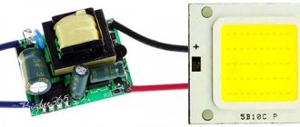
If you are interested in a driver for a 220V LED, then it is better to order or buy it. They have an average manufacturing complexity, but setup will take more time and will require setup experience.
The 220 LED driver can be removed from faulty LED lamps, luminaires and spotlights that have a faulty LED circuit. In addition, almost any existing driver can be modified. To do this, find out the model of the PWM controller on which the converter is assembled. Typically, the output parameters are set by a resistor or several. Using the datasheet, look at what the resistance should be to get the required Amps.
If you install an adjustable resistor of the calculated value, then the number of Amperes at the output will be adjustable. Just do not exceed the rated power that was indicated.
Manufacturing recommendations
For manufacturing, you will need electronic components for the selected circuit. You can purchase them in specialized stores or online. For a device based on an integrated linear stabilizer, a housing is not needed, but you need to take care of the radiator. You will also need a radiator when making a ruler using discrete elements. More complex devices must be assembled on boards. Those skilled in home technology will be able to design and etch the PCB themselves. For the rest, it is better to use a breadboard - cut off the required piece and mount the elements on it.
Breadboard mounting.
You also need to select or assemble the case, not forgetting about heat dissipation. Heat-shrinking the board is not the best option in this regard. You will also need a soldering iron with a set of consumables.
It is difficult to give general manufacturing instructions - it all depends on the chosen scheme and preferred technologies. But we can give some advice to those who have little experience in the manufacture of electronic devices:
- all connections must be carefully soldered (being careful not to overheat the elements and conductors in the insulation) - operating conditions will be associated with shaking and temperature changes, and poor-quality soldering will immediately make itself felt;
- the body of the structure must prevent water and dirt from getting inside - when installing the device under the hood, these substances will be sufficient;
- if the case is not used, the soldering points must be carefully isolated - for the same reasons;
- After assembly and performance testing, it would not be superfluous to coat the board on the solder side with varnish and dry it.
Only a careful approach to manufacturing can guarantee at least some long-term operation of a homemade product in harsh conditions.
Are you here
Home › Design engineer › 3. Electrical equipment, electrical installations › 3. Section 3.
To obtain a more constant voltage across the load when the current consumed changes, a stabilizer is connected to the output of the rectifier, which can be made according to the circuit shown in Fig. 1. This device uses zener diode V5
and control transistor
V6
.
The calculation will allow you to select all elements of the stabilizer based on the specified output voltage Un
and maximum load current
In
. However, both of these parameters should not exceed the parameters of the already calculated rectifier. And if this condition is violated, then the stabilizer is first calculated, and then the rectifier and power transformer. The stabilizer is calculated in the following order.
(Uvyp) required for the stabilizer to operate.
at a given output
(Un)
:
Uvyp = Un + 3
,
Here, number 3, which characterizes the minimum voltage between the collector and emitter of the transistor, is taken based on the use of both silicon and germanium transistors. If the stabilizer is connected to a ready-made or already calculated rectifier, in further calculations it is necessary to use the real value of the rectified voltage Uvyp
.
2. Calculate the maximum power dissipated by the transistor:
Pmax = 1.3 (Uvyp - Un) In
,
3. Select a control transistor. Its maximum permissible power dissipation must be greater than the Pmax
, the maximum permissible voltage between the emitter and the collector is greater than
Uvyp
, and the maximum permissible collector current is greater than
In
.
4. Determine the maximum base current of the regulating transistor:
Ib.max = In / h21E min
,
where: h21Emin is the minimum current transfer coefficient of the selected (according to the reference book) transistor.
.
5. Select a suitable zener diode. Its stabilization voltage must be equal to the output voltage of the stabilizer, and the value of the maximum stabilization current must exceed the maximum base current Ib max
.
6. Calculate the resistance of the resistor R1
:
R1 = (Uvyp - Ust) / (Ib max + Ist min)
,
Here R1 is the resistance of resistor R1, Ohm; Ust — zener diode stabilization voltage, V; Ib.max - calculated value of the maximum base current of the transistor, mA; Ist.min is the minimum stabilization current for a given zener diode, indicated in the reference book (usually 3...5 mA).
.
7. Determine the power dissipation of resistor R1
:
PR1 = (Uvyp - Ust)2 / R1
,
It may happen that a low-power zener diode is not suitable for the maximum stabilization current and you will have to choose a zener diode of significantly higher power - this happens with high consumption currents and using a transistor with a low h21E
.
In this case, it is advisable to introduce an additional low-power transistor V7
(Fig. 2), which will reduce the maximum load current for the zener diode (and therefore the stabilization current) by approximately
h21E
times and, accordingly, use a low-power zener diode.
The calculations presented here do not correct for changes in mains voltage, and also omit some other clarifications that complicate the calculations. It is easier to test the assembled stabilizer in action by changing its input voltage (or mains voltage) by ± 10% and more accurately select resistor R1 based on the greatest stability of the output voltage at maximum load current.
LM317
The use of LM317 (roll) does not even require any skills or knowledge of electronics. The number of external elements in the circuits is minimal, so this is an affordable option for anyone. Its price is very low, its capabilities and applications have been tested and verified many times. Only it requires good cooling, this is its main drawback. The only thing you should be wary of is low-quality Chinese LM317 microcircuits, which have worse parameters.
Due to the absence of excess noise at the output, linear stabilization microcircuits were used to power high-quality Hi-Fi and Hi-End DACs. For DACs, cleanliness of power plays a huge role, so some use batteries for this.
The maximum power for the LM317 is 1.5 Amps. To increase the number of amperes, you can add a field-effect transistor or a regular one to the circuit. At the output it will be possible to get up to 10A, set by low-resistance resistance. In this diagram, the main load is taken by the KT825 transistor.
Another way is to install an analogue with higher technical characteristics on a larger cooling system.
My experience
My friend has a VAZ PRIORA, and he is a fan of putting LED lamps in the dimensions, headlights, etc. They really didn’t walk for a long time without such stabilizing elements (a couple of months, that’s all). Now one set of cheap options has been running for three years, and all thanks to stabilization!
There are also disadvantages: such elements are placed in the break of the wire that goes to the source; “IN” and “OUT” are even indicated there where the wire should be connected and where to output it. The cost for 5 pieces is approximately 160 rubles, that is, each one is about 30. A friend set it to 11.8V, connected the wires to the boards and filled them with a glue gun, now they are not afraid of moisture.
Personally, I myself bought such boards and experimented with them, I have a power supply that produces from 15 to 24V. From it I powered two wires and connected them to the module, and from there to the LED, I set it to about 11.9. And you know, no matter how I switched the voltage in the power supply, behind the board it remained stable at 11.9V without any jumps (the whole experiment will be on video).
So the conclusion is that you can buy stabilizers (about 30 rubles apiece), the light bulbs themselves (about 50 rubles apiece) and in TOTAL you get an option for 80 - 100 rubles that will work for a very long time (3 years for sure).
Now we are watching the video version
Here is the material, I think it was useful to you, subscribe to the site and the channel will have many more interesting videos. Sincerely yours, AUTOBLOGGER.
Similar news
- Why does the alternator belt whistle? When cold or under load. ...
- How to install xenon. Is it possible to do this in the headlights of a regular car...
- How to check a fuse in a car. We use a multimeter (test...
Add a comment Cancel reply
Additional functions
In addition to performing basic functions (stabilizing the output voltage, protecting devices from increasing or decreasing voltage values, as well as from overloads and possible short circuits in the electrical network), stabilizer models are produced that have additional functionality:
- independent changes to the settings by the user - setting the limit values of the protective threshold, changing the nominal value of the voltage supplied to the output;
- sound warning system - the ability to control the operation of the device from a personal computer, remote control, as well as sound signals;
- additional protection - the presence of a self-diagnosis device, as well as protection against overheating of power relays;
- additional indicators - the presence of a digital screen, LCD display.
The price of devices equipped with additional functionality is higher, so you should choose them based on your capabilities. Even the simplest device with the appropriate parameters can protect the network and devices from overloads.
Other points
Also, when choosing a voltage stabilizer for a chandelier, you should pay attention to such an indicator as the noise level. It depends on the cooling system of the device: with active cooling, a fan is used, which produces a lot of noise. There are also passive cooling systems using a radiator made of special material - in this case, the noise level will be minimal.
So, if you carefully understand what certain characteristics of a device relate to, you can choose the most suitable voltage stabilizer model for a chandelier and avoid unnecessary costs for functions that do not affect the operation of the lighting device. Also, we should not forget that the stabilizer cannot completely eliminate the effect of flickering light, but it can smooth it out as much as possible, as well as protect lighting fixtures and lamps and extend their service life.
Buffer
After looking at the filament circuit stabilizers and the high voltage stabilizer, I present to your attention the circuit of a simple high voltage buffer:
Its function is to provide constant output impedance and suppress ripple and power supply noise. If you connect it after a conventional stabilizer, then all negative factors from feedback in the power source can be significantly reduced.
The output resistance of such a buffer is inversely proportional to the transistor transconductance and is quite low. It is also constant in the audio frequency range.
The choice of capacitors plays a big role in sound quality!!!
By the way, I found that connecting capacitors in parallel does not add to the sound quality. For example, one 20 µF capacitor sounds better than connecting two 10 µF capacitors in parallel from the same manufacturer.
Simple DIY CH
Parametric voltage stabilizer
A 12-volt voltage stabilizer for LEDs, backlights of automotive on-board systems is quickly and conveniently performed using microcircuits: LM317, LD1084, L7812, KREN 8B and similar devices. Several diodes, a resistance and the microcircuit itself are the components of such a circuit.
Stabilizer on LM317
Depending on the manufacturing option of the LM317 case, the arrangement of parts on the board is selected.
LM317 with heatsink mount
Making a stabilizer comes down to the following:
- a resistance with a nominal value of 130 Ohms is soldered to the output (Vout);
- a wire supplying voltage for stabilization is connected to the input contact (Vin);
- the adjustment input (Adj) is connected to the second terminal of the resistor.
When connecting LED lights, strips, etc. as a load. no radiator required. Assembly takes 15-20 minutes with a minimum of parts. Using a simple formula, you can calculate the value of resistance R to obtain a certain value of the permissible load current.
CH circuit on LM317
Circuit on the LD1084 chip
The use of this microassembly will help maintain the 12 V voltage constant for LED illumination devices connected to the vehicle’s on-board network.
Datasheet LD1084
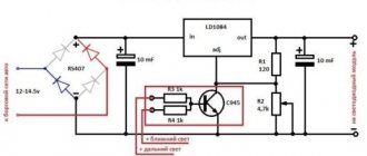
Here, to assemble a homemade CH, the following is included in the circuit binding circuit of the microcircuit:
- two electrolytic capacitors of 10 μF * 25 V;
- resistors: 1 kOhm (2 pcs.), 120 Ohm, 4.7 kOhm (can be constant);
- diode bridge RS407.
The device is assembled as follows:
- the voltage removed from the rectifier diode bridge is supplied to the input of LD1084;
- the emitter of the KT818 transistor is connected to the contact that controls the stabilization mode (Adj), the base of which is connected through two single-column resistors to the power supply circuits for the headlights (low and high);
- the output circuit of the microcircuit is connected to resistors R1 and R2, as well as a capacitor.
By the way. Resistor R2 can be taken not as a variable, but as a tuning one, using it to set the output voltage to 12 V.
SN for on-board network
Stabilizer on diodes and assembly L7812
A similar microcircuit in conjunction with a diode and capacitors can supply LEDs with a stable voltage of 12 V.
The scheme is built according to the principle outlined below:
- The 1N401 Schottky diode passes current from the positive terminal of the battery through itself and supplies it to the input of the microcircuit. In this case, the “+” of the electrolyte (330 μF capacitor) is also connected to the cathode of the diode;
- a load circuit and a “+” capacitor with a capacity of 100 μF are connected to the output of L7812;
- all negative terminals (from the battery and both electrolytic capacitors) are connected to the control input of the microcircuit.
Electrolytic capacitors are selected for a voltage of at least 25 V.
12 V stabilizer circuit on IC L7812
The simplest stabilizer is the KREN board
Schemes using rolls are quite popular. This is the name for ICs whose markings include combinations of the letters KR and EN. These are powerful SNs that allow you to supply a current of up to 1.5 A to the load. They have a stable 12 V output when a voltage of up to 35 V is applied to the input.
The circuit using this microcircuit is assembled like this:
- voltage from the positive terminal of the battery (rechargeable battery) to the bank input is supplied through a 1N4007 diode, it protects the battery circuit from reverse voltages;
- the negative terminal of the battery is connected to the control electrode KREN;
- The output voltage is supplied to the load.
If necessary, the microcircuit is screwed to the radiator.
KR142EN8B, connection diagram
Assembling 12 V voltage stabilizers with your own hands using linear and integrated MV circuits is not difficult. In this case, it is necessary to monitor the heating temperature of the housing of the elements and, when T0C is higher than permissible, install them on heat sinks (radiators).
