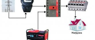
In what areas is a 12-220 V voltage inverter used?
With stable use of the battery, its charge level gradually decreases. The converter stabilizes the voltage if there is no electricity.
A 12-220 V inverter, made by yourself, will allow you to improve engineering structures in any room. The power value of devices that convert current is selected according to the total values of the operated loads. Power consumption processes can be reactive or active. Reactive loads do not fully consume the amount of energy received, causing the apparent power value to be greater than its active value.
Pure sine wave inverters are used when connecting an element whose total power is 3 kW. Significant fuel savings are ensured by the use of voltage converters and mini-power plants.
The following consumers are connected to the inverter design:
- alarm system;
- boiler;
- pumping apparatus;
- computer system.
Prologue.
I have two multimeters, and both have the same drawback - they are powered by a 9-volt Krona battery.
I always tried to have a fresh 9-volt battery in stock, but for some reason, when it was necessary to measure something with an accuracy higher than that of a pointer instrument, the Krona turned out to be either inoperative or only lasted for a few hours of operation.
The last time, I had to alternately recharge two crowns from the power supply in order to make the necessary measurements, although 12.2012 was written on the crowns. In general, patience came to an end, and I got to work.
Electrician in the house
Author: admin, April 12, 2013
DIY 12/220 voltage converter
Currently, quite a lot of 12/220 V voltage converters are produced, designed for fairly high powers.
But if you need a simple 12/220 voltage converter for your dacha or garage for lighting (TV, drill, pump), then you can make it yourself. The proposed scheme differs favorably from similar ones by the presence of a low battery alarm. This is very important if you use a car battery to power the circuit. Although it is better to take another battery, or buy a new battery for the car and use the old one for the converter. The circuit uses a minimum of parts, but the device copes with its function quite well. Such devices that convert direct voltage into alternating voltage are also called inverters.
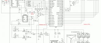
12/220 V voltage converter circuit
The diagram indicates:
- FU1 - 10A fuse.
- R1 - resistor MLT-0.5, 150 Ohm.
- R2 - variable resistor SP-1, 22 kOhm.
- R3 - trimming resistor SP3-16, 1 MOhm
- R4 - resistor MLT-0.125, 330 Ohm.
- R5, R7, R8 - resistors MLT-0.125, 2 kOhm.
- R6 - resistor MLT-0.125 1.5 kOhm.
- VD1 - zener diode KS 191A.
- C1 - capacitor K53-1, 50 µF x 50 V.
- C2, C3 - capacitors KM-5, 0.1 µF.
- C4, C5 - capacitors KM-5, 510 pF.
- VT1 is a unijunction transistor KT 117A.
- VT2, VT3 - KT 827A transistors.
- L1 - LED AL 307A.
- DD1 - K561TM2 chip.
- T1 - transformer.
Description of the circuit operation
The generator, assembled on transistor VT1, generates oscillations with a frequency of 100 Hz, the frequency can be adjusted by trimming resistor R3. Trigger DD1.2 divides the frequency in half and at outputs 12 and 13 of the trigger, pulses of opposite amplitude with a frequency of 50 Hz are formed. The pulses alternately open transistors VT2 and VT3, which are connected according to the circuit of a push-pull power amplifier. The load of transistors VT1, VT2 is windings 1 and 2 of step-up transformer T1, on the secondary winding 3 of which an alternating voltage of 220V, 50 Hz is generated.
The stabilizer made on VD1, R1 and smoothing capacitor C1 serve to power the microcircuit and generator and eliminate the influence of the operation of key transistors VT1, VT2 on the operation of the circuit, and capacitors C5, C4 reduce the time of the transition process (help these transistors switch faster). Trigger DD1 turns on the signal LED L1 when the battery voltage drops to a predetermined value, which is set by variable resistor R2.
Setting up the circuit
- Disconnect “+” from the connection of windings 1 and 2.
- Check the frequency at the bases of transistors VT2 and VT3 using an oscilloscope, adjust, if necessary, with resistor R3 to 50Hz.
- Reduce the power supply voltage to 10-11V. Achieve constant lighting of LED L1 using variable resistor R2.
- Connect “+” back to the connection point of windings 1 and 2.
- Check the operation of the device on a fully charged battery.
Circuit details
Transistors VT2, VT3 KT 827 can be taken with any letter index, but preferably with the highest base current transfer coefficient.
Zener diode VD1 can be replaced with any other with a stabilization voltage of 8-9V.
The transformer can be made on the basis of the PLM 27-40-58 magnetic circuit. Wind primary windings 1 and 2 with PBD-2 (PSD-2) wire, 15 turns each. Wind the secondary winding 3 with PEV-2 wire, 0.64 mm - 704 turns.
Install capacitor C2 directly at the terminals of microcircuit DD1.
If you do not have the required value of resistors and capacitors, you can make up the required one from several parts, as described in this article.
A printed circuit board can be made using the technology described in this article.
Converter parameters 12/220
This voltage converter was tested with a load of 100 W. The current consumption of the converter is no more than 10A, the current consumption without load is no more than 1A. The converter can withstand the starting currents of an electric pump and electric drill. The maximum output voltage drop is 10 V.
To power equipment that requires a sinusoidal signal, a capacitor can be installed at the output to smooth out the squareness of the pulses; its capacitance must be selected to achieve the best result; the selection can begin with a capacitance of 1 μF. The capacitor must be designed for a voltage of at least 400V.
You can share the article with your friends by clicking on the social media button below. Please write questions and suggestions in the comments, the article can be supplemented. You can also subscribe to article updates by filling out the subscription form below, spam will not be sent to your email, and you can unsubscribe from updates at any time.
Circuit of a pulse voltage converter 1.5 - 9 Volts.
As a voltage converter from 1.5 V to 9 V, A. Chaplygin’s circuit, published in the magazine “Radio” (11.2001, p. 42), was chosen.
This is one of the diagrams that perfectly illustrates the expression: “Everything ingenious is simple.”
C1, C2 – 22µF
VT1, VT2 – KT209K
B1 – 1… 1.5V
Indeed, the circuit consists of only five parts, two of which are filter capacitors. Instead of a high-frequency voltage rectifier, base-emitter junctions of the transistors of the generator itself are used. At the same time, the magnitude of the base current becomes proportional to the magnitude of the load current, which makes the converter very economical.
Another feature of the generator is the interruption of oscillations when there is no load, which automatically solves the problem of power management. Simply put, such a “Krona”, or more precisely, the converter built into it, will turn on itself when it is required to power something and turn off when the load is turned off.
Transformer TV1 is wound on a 2000NM ring magnetic core with dimensions K7x4x2. Windings III and IV each contain 28 turns of wire Ø0.16mm, and windings I, II each contain 4 turns of wire Ø0.25mm.
How to calculate the number of turns of a single-layer winding for a pulse transformer on a ring core is written here.
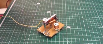
Installation of radio elements
All that remains is to assemble the device. Since there are not so many components in the circuit, they can be placed not on a printed circuit board, but mounted mounted to a radiator, that is, to the device body. We solder the pin legs with a solid copper wire of a sufficiently large cross-section, then the connection point is strengthened with 5–7 turns of thin transformer wire and a small amount of POS-61 solder. After the connection has cooled, it is insulated with a thin heat-shrink tube.
High-power circuits with complex secondary circuitry may require a printed circuit board with transistors lined up on the edge for loose attachment to the heatsink. Fiberglass with a foil thickness of at least 50 microns is suitable for making a signet; if the coating is thinner, reinforce the low-voltage circuits with jumpers made of copper wire.
Today it’s easy to make a printed circuit board at home - the Sprint-Layout program allows you to draw clipping stencils for circuits of any complexity, including double-sided boards. The resulting image is printed by a laser printer on high-quality photo paper. Then the stencil is applied to cleaned and degreased copper, ironed, and the paper is washed away with water. The technology is called “laser ironing” (LIT) and is described on the Internet in sufficient detail.
You can etch away copper residues with ferric chloride, electrolyte, or even table salt; there are plenty of ways. After etching, the baked-on toner needs to be washed off, drill mounting holes with a 1 mm drill and go over all the tracks with a soldering iron (submerged arc) to tin the copper of the contact pads and improve the conductivity of the channels.
Final assembly of a pulse voltage converter.
Before final assembly, all elements of the circuit were connected with stranded wire, and the circuit's ability to receive and transmit energy was tested.
To prevent short circuits, the pulse voltage converter was insulated on the contact side with silicone sealant.
Then all the structural elements were placed in the Krona body. To prevent the front cover with the connector from being recessed inside, a celluloid plate was inserted between the front and back walls. After which, the back cover was secured with “88N” glue.
To charge the modernized Krona, we had to make an additional cable with a 3.5mm jack plug at one end. At the other end of the cable, to reduce the likelihood of a short circuit, standard device sockets were installed instead of similar plugs.
Inverter housing
The first thing to consider is the electricity conversion losses released in the form of heat on the circuit switches. On average, this value is 2–5% of the rated power of the device, but this figure tends to increase due to improper selection or aging of components.
Heat removal from semiconductor elements is of key importance: transistors are very sensitive to overheating and this is expressed in the rapid degradation of the latter and, probably, their complete failure. For this reason, the base for the case should be a heat sink - an aluminum radiator.
For radiator profiles, a regular “comb” with a width of 80–120 mm and a length of about 300–400 mm is suitable. The field-effect transistor screens are attached to the flat part of the profile with screws - metal spots on their rear surface. But this is not all simple: there should be no electrical contact between the screens of all transistors in the circuit, so the radiator and fastenings are insulated with mica films and cardboard washers, while a thermal interface is applied to both sides of the dielectric spacer with metal-containing paste.
Causes of through currents
A typical circuit of the power part of an IGBT-based inverter is shown in Figure 1. In normal operation, the upper and lower side transistors should be turned on in turn. The simultaneous presence of two transistors in a conducting state will lead to a short circuit of the power source and the appearance of overcurrents, the magnitude of which is limited only by the low active resistance in the power circuit.
Rice. 1. Typical diagram of the power section of the inverter
Of course, no one designs an inverter so that the high- and low-side transistors are on at the same time. However, IGBTs are not ideal switches and have a finite duration of on and off times, which are not only unequal to each other, but also depend on many factors, including the temperature of the crystal and the value of the switched current. Therefore, in practice, it is recommended to introduce a small delay into the control signals of transistors, known as “Dead Time”, ensuring that the transistor of one arm will be open only after the transistor of the other arm is completely closed.
How things are now
Modern element base makes it possible today to simplify the above-described design to a minimum.
Chip KR1211EU1
- To do this, you will first have to replace the bulky generator with a special microcircuit of the KR1211EU1 brand. Please note that this microcircuit is domestically produced; you will not find foreign analogues.
- Instead of power switches, it is best to use IRL2505 transistors; they are powerful and are used in car electrical circuits. By the way, their resistance is 0.008 Ohm, which is not comparable to mechanical contacts.
Device for charging gadgets
The portable device can charge a smartphone or tablet. A laptop or video camera is not a problem for him. Even a soldering iron can be provided with appropriate “power”. The fact is that the usual voltage for which the devices are designed is 220 Volts. Making your own battery device gives an output of 14.8V. This is not enough for a laptop and a lot for a smartphone.
Therefore, a universal small inverter is simply necessary. You can assemble it thanks to AKA KASYAN products. Small capacitances provide the required current. 5A. The manufacturing process is fully described on specialized websites.
Note!
How to make a hot smoked smokehouse with your own hands: drawings, dimensions, choice of material, photos of finished options
How to make a chicken feeder with your own hands: step-by-step instructions with photos and descriptions
Do-it-yourself furnace: detailed instructions on how to make a furnace with maximum efficiency
Generator with output voltage doubling
Figure 4 shows a generator with an output stage that doubles the output voltage. When transistor VT3 is closed, only a small supply voltage is applied to the LED.
The electrical resistance of the LED is high due to the pronounced nonlinearity of the current-voltage characteristic and is much higher than the resistance of resistor R6. Therefore, capacitor C2 is connected to the power source through resistors R5 and R6.
Rice. 4. Circuit of a low-voltage converter with doubling the output voltage.
Although resistor R6 is used instead of a germanium diode, the principle of operation of the voltage doubler remains the same: charging capacitor C2 with transistor VT3 closed through resistors R5 and R6, followed by connecting the charged capacitor in series with the power source.
When a voltage doubled in this way is applied, the dynamic resistance of the LED at a steeper section of the current-voltage characteristic becomes about 100 Ohms or less for the duration of the capacitor discharge, which is much lower than the resistance of the resistor R6 shunting the capacitor.
The use of resistor R6 instead of a germanium diode allows you to expand the operating range of supply voltages (from 0.8 to 6 V). If there were a germanium diode in the circuit, the supply voltage of the device would be limited to 1.6...1.8 V.
If the supply voltage were further increased, the current through the LED and germanium diode would increase to an unacceptably high value and irreversible damage would occur.