See also: Electronic ballast for LED lamp. Circuit design.
Educational article on LED current stabilizers and more. Schemes of linear and pulsed current stabilizers are considered.
A current stabilizer for LEDs is installed in many luminaire designs. LEDs, like all diodes, have a nonlinear current-voltage characteristic. This means that when the voltage across the LED changes, the current changes disproportionately. As the voltage increases, at first the current increases very slowly, and the LED does not light up. Then, when the threshold voltage is reached, the LED begins to glow and the current increases very quickly. With a further increase in voltage, the current increases catastrophically and the LED burns out.
The threshold voltage is indicated in the characteristics of LEDs as forward voltage at rated current. The current rating for most low-power LEDs is 20 mA. For high-power LED lighting, the current rating may be higher - 350 mA or more. By the way, high-power LEDs generate heat and must be installed on a heat sink.
For the LED to work properly, it must be powered through a current stabilizer. For what? The fact is that the LED threshold voltage varies. Different types of LEDs have different forward voltages, even LEDs of the same type have different forward voltages - this is indicated in the characteristics of the LED as the minimum and maximum values. Consequently, two LEDs connected to the same voltage source in a parallel circuit will pass different currents. This current can be so different that the LED may fail earlier or burn out immediately. In addition, the voltage stabilizer also has a drift of parameters (from the primary power level, from the load, from temperature, simply over time). Therefore, it is undesirable to turn on LEDs without current equalization devices. Various current equalization methods are discussed separately. This article discusses devices that set a very specific, specified current - current stabilizers.
Device selection
Voltage stabilizer 12 volts
When choosing a stabilizer, take into account the following characteristics:
- Dimensions. The selected stabilizer must be compactly placed in its planned installation location with normal access.
- View. Of the commercially available devices, the most reliable, compact and inexpensive are stabilizers based on small microcircuits.
- Possibility of self-repair. Since even the most reliable devices fail, it is necessary to give preference to repairable stabilizers, radio components for which are commercially available in sufficient quantities and at an affordable price.
- Reliability. The selected stabilizer must provide a constant voltage value without significant deviations from the range declared by their manufacturer.
- Price. For the electrical system of a car, it is enough to purchase a device costing up to 200 rubles.
Parameters of LM-317 microcircuits
The integrated circuit (IC) is manufactured in a plastic case, with the possibility of installation on a heat sink (radiator). It has three outputs and provides the ability to linearly regulate voltage and current. The IC is intended for use in regulated power supplies (PSUs) and LED circuits. For your information. The popular model of this device is made in the TO-220 case and has the letter T as part of the marking. This letter indicates the type of case.
Each of the three pins of LM317 has the following purpose:
- VIn – input where the voltage intended for regulation is supplied;
- VOut is the output from which the required voltage is removed; it has electrical contact with a bracket for attaching to a board or radiator;
- Adj is an adjustable input through which the output voltage is changed using a variable resistor.
Count the pins from left to right, holding the microcircuit with the front side facing you.
Pinout LM317 TO-220(T)
In addition to electrical quality indicators, the assembly has physical and protective characteristics. These include the following points:
- housing type – TO-220, TO-220FP, TO-3, D2PAK, SOT-23;
- the type of material from which the body is made is plastic;
- short circuit protection – ISCCL (Internal Short-Circuit Current Limiting);
- TOP (Thermal Overload Protection) – protection against thermal overloads;
- control over the maximum power dissipation OS-AC (Output Safe-Area Compensation).
Attention! Sensors located inside the IC monitor the set thermal limit and turn off the chip if the maximum power dissipation is exceeded. To do this you will need the following parts and devices:
To do this you will need the following parts and devices:
- IPT (direct current source);
- IC LM-317;
- resistor R with a resistance from 1 to 110 Ohms and a power reserve calculated using the formula already discussed;
- Light-emitting diode.
Do-it-yourself current stabilizer circuit for an LED
To install lighting on a car, a larger number of LED lamps, you can increase the stabilizer current to 3 A. For this, a powerful transistor KT 818 is included in the circuit.
Increasing the stabilization current
You can use 12 volt voltage stabilizers for automotive LEDs. Illumination of panels, license plates, installation of white LED lamps as side or running lights - these are just a few installation points.
LED strip on a car headlightAttention! The durability of a diode emitting light depends not so much on a stable supply voltage, but on the current flowing through it. If elements of the AlInGaP/GaAs model can withstand current overloads, then GaInN/GaN-based LED diodes will not last even a couple of hours
An even glow of emitting diodes with different connections (parallel or series connected circuits) is possible at the same current values.
Not only specialized microcircuits can be used as a current stabilizer for LEDs. The LM317 circuit is very popular among radio amateurs.
To turn this circuit into a current stabilizer, it is enough to exclude resistor R1 from the circuit. The inclusion of LM317 as a linear current stabilizer is as follows.
R1=1.25*I0.
W=I2R1.
Also, two flexible conductors need to be soldered to the input and output of the microcircuit and the design will be ready. If it is intended to power a powerful LED using the current stabilizer on LM317, the microcircuit must be equipped with a radiator that will ensure heat removal. As a radiator, you can use a small aluminum plate with an area of 15-20 square centimeters.
Read more: How to make acoustic doors with your own hands
When making booster designs, you can use filter coils from various power supplies as chokes. For example, ferrite rings from computer power supplies are well suited for these purposes; several dozen turns of enameled wire with a diameter of 0.3 mm should be wound around them.
Adjustable Voltage Stabilizer for Charger
A charger for car batteries is an irreplaceable thing that every car enthusiast should have, no matter how good the battery is, since it can fail at the most inconvenient moment.
We have repeatedly reviewed the designs of numerous chargers on the pages of the site. The charger is, in theory, nothing more than a power supply with current and voltage stabilization. It works simply - we know that the voltage of a charged car battery is about 14-14.4 Volts, you need to set exactly this voltage on the charger, then set the desired charging current, in the case of acid starter batteries this is a tenth of the battery capacity, for example - a 60 A battery /h, we charge it with a current of 6 Amps.
Adjustable Voltage Stabilizer for Charger
As a result, as the battery charges, the current will drop and eventually reach zero - as soon as the battery is charged. This system is used in all chargers; the charging process does not need to be constantly monitored, since all output parameters of the charger are stable and do not depend on changes in mains voltage.
Based on this, it becomes clear that to build a charger you need to have three nodes.
1) Step-down transformer or switching power supply plus rectifier2) Current stabilizer3) Voltage stabilizer
With the help of the latter, the voltage threshold is set to which the battery will be charged, and today we will talk specifically about the voltage stabilizer.
The system is incredibly simple, only 2 active components, minimal costs, and assembly will take no more than 10 minutes if all components are available.
What we have . a field-effect transistor as a power element, an adjustable zener diode that sets the stabilization voltage, this voltage can be set manually using a variable (or better yet, a tuning, multi-turn) 3.3 kOhm resistor. A voltage of up to 50 Volts can be supplied to the input of the stabilizer, and at the output we already obtain a stable voltage of the required rating.
The minimum possible voltage is 3 Volts (depending on the field-effect transistor), the fact is that in order for the field-effect transistor to open at its gate, you need to have a voltage above 3 volts (in some cases more) except for field-effect transistors that are designed to operate in circuits with a logical control level.
On the ratio of the dimensions of the inertial stabilizer
When the camera deviates from the horizontal axis, the operator is forced to fix the stabilizer handle in his hand. The moment of force transmitted to the operator's hand is directly proportional to the length of the vertical bar and the weight of the camera, and inversely proportional to the diameter of the handle. Therefore, the ease of camera control depends on the diameter of the handle. To improve tactile sensations about the position of the handle in the hand, it is useful to make small concentric indentations on it.
It must be said that the dimensions of each part of the stabilizer are a compromise between one or another device parameters.
For example, the thinner the handle, the more difficult it is to stabilize the Steadicam when accelerating, but the thicker the handle, the weaker the tactile sensation of the horizon.
Another compromise is the choice between the size and weight characteristics of the structure and the quality of stabilization. The longer the horizontal bar and the heavier the weights at its ends, the higher the quality of stabilization. However, if the length of the horizontal bar increases, its end may fall into the field of view of the lens, and the increase in weight makes carrying the equipment less comfortable. I do not recommend increasing the weight of the equipped stabilizer by more than 2.5 kg, and it is better to adjust the maximum size to your favorite case.
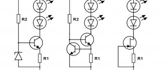
Assembling a current stabilizer from two transistors
In this circuit, the sensor functions are performed by resistor R2. Its value when connecting LEDs is selected using the formula:
0.6/In (load current).
An increase in In opens VT2, which, in turn, locks the transition of transistor VT1.
Experts consider a significant voltage drop across the main transistor to be a disadvantage of the circuit. There are no problems when connecting several LEDs. However, as the load increases, it is necessary to place VT1 on a large radiator to ensure effective ventilation of the working volume. Such solutions are used to create powerful chargers.
Converter based on AF generator
In the generator presented in Figure 5, simultaneously with light pulses, ringing pulses of sound frequency are generated. The frequency of sound signals is determined by the parameters of the oscillatory circuit formed by the winding of the telephone capsule and capacitor C2.
Rice. 5. Schematic diagram of a voltage converter for an LED based on an AF generator.
Design and operating principle
The stabilizer ensures constant current when it deviates. The stabilizer ensures constant operating current of LED diodes when it deviates from the norm. It prevents overheating and burnout of LEDs, maintains constant flow during voltage surges or battery discharge.
The simplest device consists of a transformer, a rectifier bridge connected to resistors and capacitors. The action of the stabilizer is based on the following principles:
- supplying current to the transformer and changing its limiting frequency to the mains frequency - 50 Hz;
- voltage adjustment to increase and decrease with subsequent frequency equalization to 30 Hz.
The conversion process also uses high-voltage rectifiers. They determine the polarity. Stabilization of the electric current is carried out using capacitors. Resistors are used to reduce interference.
Device and technical characteristics
Adjustable current stabilizers are successfully used in power supply circuits and various chargers. These devices are designed to stabilize the current at a given level. Due to their low cost, the development of circuits for most electronic devices is greatly simplified. The operation of these devices is clearly demonstrated by a simple adjustable voltage and current stabilizer.
To do this, you should use an ideal current source with an infinitely large electromotive force and significant internal resistance. Such parameters make it possible to obtain current in the circuit with the required characteristics, regardless of the load resistance. Thus, an ideal source creates a current that has a constant value with a varying load resistance ranging from a short circuit to infinity. To maintain the current value at a constant level, the EMF value must vary from a value greater than zero to infinity
As a result, a stable current value is obtained due to an important property of the current source: with a change in the load resistance, the EMF of the current source changes so that the current value remains constant
Unlike direct current, real current sources are able to maintain current at the desired level only over a limited range of load voltage and limited load resistance. A real source can operate even with zero load resistance, as well as in output short circuit mode, without any difficulties. That is, if the output is accidentally shorted, the device will simply switch to another operating mode, where the load resistance is above zero.
As a rule, it is practiced to use a real current source with a real voltage source. Such sources include: an electrical network with a voltage of 220 V, a frequency of 50 Hz, batteries, laboratory power supplies, solar panels, gasoline generators and other electricity suppliers. With any of them, an adjustable current stabilizer is connected in series. The output of this device is accordingly used as a current source.
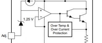
ADJUSTABLE POWER SUPPLY WITH OVERLOAD ALARM
An audible alarm allows the user to quickly respond to an emergency if an overload of the power source occurs during experiments with various electronic equipment. The diagram of a power supply with an audible alarm for excess current consumption is shown in the figure.
The diode rectifier VD1-VD4 is powered by a transformer, the secondary casing of which is designed for a voltage of 18 V with a load current of at least 1 A. The adjustable voltage stabilizer is made using transistors VT2 - VT5 according to a well-known circuit. The variable resistor R3 at the output of the stabilizer can set the voltage from 0 to +15 V.
How to avoid 3 common mistakes when working with a triac.
- The letter after the triac code indicates its maximum operating voltage: A – 100V, B – 200V, C – 300V, D – 400V. Therefore, you should not take a device with the letters A and B to adjust 0-220 volts - such a triac will fail.
- A triac, like any other semiconductor device, gets very hot during operation; you should consider installing a radiator or an active cooling system.
- When using a triac in load circuits with high current consumption, it is necessary to clearly select the device for the stated purpose. For example, a chandelier with 5 bulbs of 100 watts each will consume a total current of 2 amperes. When choosing from the catalog, you need to look at the maximum operating current of the device. Thus, the MAS97A6 triac is designed for only 0.4 amperes and will not withstand such a load, while the MAS228A8 is capable of passing up to 8 A and is suitable for this load.
Circuits of stabilizers and current regulators
Everyone knows that LED light bulbs require twelve volts of power. In a car network, this value can reach up to 15 V. LED elements are very sensitive, such surges are reflected negatively on them. LED lamps may burn out or produce poor quality light (flash, lose brightness, etc.).
To make the LEDs last longer, drivers (resistors) are included in the car's electrical network. When there is instability in the network, devices are installed that maintain a constant value. There are several simple microcircuits that you can use to make a voltage stabilizer with your own hands. All components included in the chain can be purchased at specialized stores. Having basic knowledge of electrical engineering, making devices will not be difficult.
On Krenka
In order to construct a simple 12 volt voltage stabilizer with your own hands, you will need a microcircuit with a consumption of 12 V. In this case, an adjustable 12 V voltage stabilizer LM317 is suitable. It can operate in an electrical network where the input parameter is up to 40 V. In order for the device to operate stably, it is necessary to provide cooling.
Chip rolls
The current regulator on the LM317 requires a small current of up to 8 mA to operate, and this value usually remains the same even when large current flows through the LM317 bank or when the input value changes. This is implemented using the R3 component.
You can use the R2 element, but the limits will be small. If the resistance of LM317 remains constant, the current flowing through the device will also be stable (author of the video - Created in Garage).
The input value for the LM317 bank can be up to 8 mA and higher. Using this microcircuit, you can come up with a current stabilizer for DRLs. This device can act as a load in the on-board network or a source of electricity when recharging the battery. Making a simple voltage regulator LM317 is not difficult.
On two transistors
Today, stabilizing devices for the on-board network of a 12 V car, developed using two transistors, are popular. This microcircuit is used as a voltage stabilizer for DRLs.
Resistor R2 is a current-distributing element. As the current in the network increases, the voltage increases. If it reaches a value from 0.5 to 0.6 V, element VT1 opens. Opening component VT1 closes element VT2. As a result, the current passing through VT2 begins to decrease. You can use a Mosfet field-effect transistor together with VT2.
Element VD1 is included in the circuit when the values are in the range from 8 to 15 V and are so large that the transistor may fail. With a powerful transistor, readings in the on-board network of about 20 V are acceptable. Do not forget that the Mosfet transistor will open if the readings at the gate are 2 V.
On an operational amplifier (op-amp)
A voltage stabilizer for LEDs based on an op-amp is assembled if it is necessary to create a device that will operate in an extended range. In the case under consideration, the element that will set the rectified current is R7. Using the DA2.2 operational amplifier, you can increase the voltage level in the current-setting component. The task of the DA 2.1 component is to control the reference voltage.
When creating the circuit, you should take into account that it is designed for 3A, so more current is required, which must be supplied to the XP2 connector. In addition, the functionality of all components of this device should be ensured.
The made stabilizing device for a car must have a generator, the role of which is performed by REF198. To properly configure the device, the slider of resistor R1 must be set to the upper position, and resistor R3 must be used to set the required value of the rectified current 3A. To suppress possible excitations, elements R,2 R4 and C2 are used.
On a pulse stabilizer chip
If a rectifier for a car must provide high efficiency in the network, it is advisable to use switching components, creating a switching voltage stabilizer. The MAX771 circuit is popular.
Switching rectifier circuit
The switching current stabilizer is characterized by an output power of 15 W. Elements R1 and R2 divide the output of the circuit. If the divided voltage exceeds the reference voltage, the rectifier automatically reduces the output value. Otherwise, the device will increase the output parameter.
Assembly of this device is advisable if the level exceeds 16 V. R3 components are current. To eliminate the high load drop across this resistor, an op-amp should be included in the circuit.
Foreign and Russian analogues
What can replace lm317? Complete analogues of the microcircuit are GL317, SG317, UPC317, ECG1900. A very well-known domestic analogue of lm317t with a fixed voltage is the KP142EN12 microcircuit. If you need an adjustable linear stabilizer, then KREN12A is suitable (B is also possible).
Operational safety
The maximum voltage between input and output should not exceed 40 V. Dissipation power should not exceed 20 W. The soldering temperature should not exceed 260 °C, while maintaining a distance from the microcircuit body of more than 1.6 mm and a heating time of up to 10 seconds. The storage temperature of the device should be in the range from -65 to + 150 °C, operating temperature no more than + 150 °C.
These are maximum values that can damage the device or affect its stability. The microcircuit is well protected from thermal overload and contact short circuit. However, you should not exceed the permissible parameters during operation in order to avoid its failure and achieve maximum reliable operation.
Scheme number 1
There was a stabilized switching power supply that gave an output voltage of 17 volts and a current of 500 milliamps. A periodic change in voltage was required in the range of 11 - 13 volts. And the well-known voltage regulator circuit on one transistor coped with this perfectly. I added only an indication LED and a limiting resistor to it. By the way, the LED here is not only a “firefly” signaling the presence of output voltage. With the correct value of the limiting resistor, even a small change in the output voltage is reflected in the brightness of the LED, which provides additional information about its increase or decrease. The output voltage could be changed from 1.3 to 16 volts.
KT829, a powerful low-frequency silicon compound transistor, was installed on a powerful metal radiator and it seemed that, if necessary, it could easily withstand a heavy load, but a short circuit occurred in the consumer circuit and it burned out. The transistor has a high gain and is used in low-frequency amplifiers - you can really see its place there and not in voltage regulators.
On the left are removed electronic components, on the right are prepared for replacement. The difference in quantity is two items, but in terms of the quality of the circuits, the former and the one that was decided to be collected, it is incomparable. This begs the question: “Is it worth assembling a scheme with limited capabilities when there is a more advanced option “for the same money”, in the literal and figurative sense of this saying?”
LED Power Options
For LEDs, in addition to the rated current, there is another important parameter - forward voltage drop. The role of this parameter is also significant, which is why it is indicated in the first row of technical parameters of a semiconductor device.
In order for current to begin to flow through the pn junction, some minimum forward voltage Umin.pr must be applied to it. The value of the minimum forward voltage is indicated in the documentation of the LED and is reflected in the graph of the volt-ampere characteristics (VAC).
In the green section of the LED’s current-voltage characteristic it can be seen that only when Umin.pr. current Ipr begins to flow. A further slight increase in Upr leads to a sharp increase in Ipr. That is why even small voltage drops above Umax..pr. are detrimental to the LED crystal. At the moment of exceeding Umax.pr. the current reaches its peak and the crystal is destroyed. For each type of LED, there is a rated current and a corresponding voltage (nameplate data), at which the device must work out the declared service life.
LM317
The use of LM317 (roll) does not even require any skills or knowledge of electronics. The number of external elements in the circuits is minimal, so this is an affordable option for anyone. Its price is very low, its capabilities and applications have been tested and verified many times. Only it requires good cooling, this is its main drawback. The only thing you should be wary of is low-quality Chinese LM317 microcircuits, which have worse parameters.
Due to the absence of excess noise at the output, linear stabilization microcircuits were used to power high-quality Hi-Fi and Hi-End DACs. For DACs, cleanliness of power plays a huge role, so some use batteries for this.
The maximum power for the LM317 is 1.5 Amps. To increase the number of amperes, you can add a field-effect transistor or a regular one to the circuit. At the output it will be possible to get up to 10A, set by low-resistance resistance. In this diagram, the main load is taken by the KT825 transistor.
Another way is to install an analogue with higher technical characteristics on a larger cooling system.
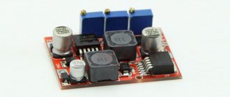
Simple current converter
Assembling a miniature current converter with your own hands is considered quite simple. Such voltage stabilizers are usually manufactured in current stabilizing mode. However, do not confuse the maximum voltage for the entire block and the maximum load on the PWM controller. A system of low-voltage capacitors of 20 V can be installed on the block, and a pulse microcircuit can have an input of up to 35 V. The simplest DIY LED current stabilizer is the LM317 version. You only need to calculate the resistor for the LED using an online calculator.
For the LM317, you can use available power (for example, a 19 V power supply from a laptop, a 24 V or 32 V power supply from a printer, or a 9 or 12 V power supply from consumer electronics). The advantages of such a converter include its low price, minimal number of parts, high reliability, and availability in stores. It is not rational to assemble a more complex current stabilizer circuit with your own hands. Therefore, if you are not an experienced radio amateur, then a pulse current stabilizer will be much easier and faster to buy ready-made. If necessary, it can be modified to the required parameters.
To assemble the LM317, no special knowledge or skills in electronics are required (the number of external elements in the circuits is minimal). Such a simple current stabilizer is very cheap, and its capabilities have been tested many times in practice.
The only downside is that the LM317 may require additional cooling. You should also be wary of Chinese LM317 microcircuits with lower parameters. In any case, the cost is more than affordable, and delivery is included in the price. Chinese manufacturers perform rather labor-intensive work at a product price of 30-50 rubles per piece. Unneeded spare parts can be sold on Avito or forums on the Internet.
Assembling a simple stabilizer with your own hands
An LED is a semiconductor device that requires current to operate. Turning on LEDs through a stabilizer is considered the most correct. The duration of operation of the LED without loss of brightness depends on its operating mode. The main advantage of the simplest stabilizers (drivers), such as the LM317 stabilizer chip, is that they are quite difficult to burn. The LM317 connection diagram requires only two parts: the microcircuit itself, which is included in the stabilization mode, and a resistor.
- You will need to buy a variable resistor with a resistance of 0.5 kOhm (it has three terminals and an adjustment knob). You can order it online or buy it at Radio Amateur.
- The wires are soldered to the middle terminal, as well as to one of the extreme ones.
- Using a multimeter turned on in resistance measurement mode, the resistance of the resistor is measured. It is necessary to achieve a maximum reading of 500 Ohms (so that the LED does not burn out when the resistor resistance is low). How to check the LED itself with a multimeter is written here.
- After carefully checking the correct connections before connecting, the circuit is assembled.
The maximum power of LM317 is 1.5 Amperes. If you want to increase the current, you can add a field-effect or regular transistor to the circuit. As a result, for a transistor-based device, a supply of 10 A can be achieved at the output (set by low-resistance resistance). For these purposes, you can use the KT825 transistor or install an analogue with better technical characteristics and a cooling system.
In any case, the range of modules and blocks sold is quite wide, so a device with the required parameters can be assembled in a minimum amount of time. The efficiency depends on the difference between the input and output voltages, as well as on the operating mode.
Are you here
Home › Design engineer › 3. Electrical equipment, electrical installations › 3. Section 3.
To obtain a more constant voltage across the load when the current consumed changes, a stabilizer is connected to the output of the rectifier, which can be made according to the circuit shown in Fig. 1. This device uses zener diode V5
and control transistor
V6
.
The calculation will allow you to select all elements of the stabilizer based on the specified output voltage Un
and maximum load current
In
. However, both of these parameters should not exceed the parameters of the already calculated rectifier. And if this condition is violated, then the stabilizer is first calculated, and then the rectifier and power transformer. The stabilizer is calculated in the following order.
(Uvyp) required for the stabilizer to operate.
at a given output
(Un)
:
Uvyp = Un + 3
,
Here, number 3, which characterizes the minimum voltage between the collector and emitter of the transistor, is taken based on the use of both silicon and germanium transistors. If the stabilizer is connected to a ready-made or already calculated rectifier, in further calculations it is necessary to use the real value of the rectified voltage Uvyp
.
2. Calculate the maximum power dissipated by the transistor:
Pmax = 1.3 (Uvyp - Un) In
,
3. Select a control transistor. Its maximum permissible power dissipation must be greater than the Pmax
, the maximum permissible voltage between the emitter and the collector is greater than
Uvyp
, and the maximum permissible collector current is greater than
In
.
4. Determine the maximum base current of the regulating transistor:
Ib.max = In / h21E min
,
where: h21Emin is the minimum current transfer coefficient of the selected (according to the reference book) transistor.
.
5. Select a suitable zener diode. Its stabilization voltage must be equal to the output voltage of the stabilizer, and the value of the maximum stabilization current must exceed the maximum base current Ib max
.
6. Calculate the resistance of the resistor R1
:
R1 = (Uvyp - Ust) / (Ib max + Ist min)
,
Here R1 is the resistance of resistor R1, Ohm; Ust — zener diode stabilization voltage, V; Ib.max - calculated value of the maximum base current of the transistor, mA; Ist.min is the minimum stabilization current for a given zener diode, indicated in the reference book (usually 3...5 mA).
.
7. Determine the power dissipation of resistor R1
:
PR1 = (Uvyp - Ust)2 / R1
,
It may happen that a low-power zener diode is not suitable for the maximum stabilization current and you will have to choose a zener diode of significantly higher power - this happens with high consumption currents and using a transistor with a low h21E
.
In this case, it is advisable to introduce an additional low-power transistor V7
(Fig. 2), which will reduce the maximum load current for the zener diode (and therefore the stabilization current) by approximately
h21E
times and, accordingly, use a low-power zener diode.
The calculations presented here do not correct for changes in mains voltage, and also omit some other clarifications that complicate the calculations. It is easier to test the assembled stabilizer in action by changing its input voltage (or mains voltage) by ± 10% and more accurately select resistor R1 based on the greatest stability of the output voltage at maximum load current.
Functional diagrams by type of control circuit
The switching voltage stabilizer is an automatic regulation system. The setting parameter for the control loop is the reference voltage, which is compared with the output voltage of the stabilizer. Depending on the mismatch signal, the control device changes the ratio of the durations of the open and closed states of the key.
In the block diagrams presented below, three functional units can be distinguished: a switch (1), an energy storage device (2) (sometimes called a filter) and a control circuit. In this case, the switch (1) and the energy storage device (2) together form the power part of the voltage stabilizer, which, together with the control circuit, form a control loop. There are three schemes based on the type of control circuit.
With Schmitt trigger
A voltage stabilizer with a Schmitt trigger is also called a relay or on-off regulator. In it, the output voltage is compared with the lower and upper thresholds of the Schmitt trigger (4 and 3) using a comparator (4), which is usually the input part of the Schmitt trigger. When the switch (1) is closed, the input voltage is supplied to the energy storage device (2), the output voltage increases, and after reaching the upper threshold Umax
The Schmitt trigger switches to a state that opens the switch (1).
The accumulated energy is consumed in the load, while the voltage at the output of the stabilizer drops, and after reaching the lower operating threshold Umin
, the Schmitt trigger switches to a state that closes the switch. The described process is then repeated periodically. As a result, a pulsating voltage is formed at the output, the ripple range of which depends on the difference in the Schmitt trigger thresholds.
Such a stabilizer is characterized by a relatively large, fundamentally irremovable voltage ripple at the load and a variable conversion frequency, depending on both the input voltage and the load current.
With pulse width modulation
Block diagram of a voltage stabilizer with PWM
As in the previous circuit, during operation the energy storage device (2) is either connected to the input voltage or transfers the accumulated energy to the load
As a result, the output has a certain average voltage value, which depends on the input voltage and the duty cycle of the key control pulses (1). The subtractor-amplifier on the operational amplifier (4) compares the output voltage with the reference voltage (6) and amplifies the difference, which is fed to the modulator (3)
If the output voltage is less than the reference voltage, then the modulator increases the ratio of the time the switch is open to the period of the clock generator (5). When the input voltage or load current changes, the duty cycle of the switch control pulses changes in such a way as to ensure a minimum difference between the output and reference voltage.
In such a stabilizer, the conversion frequency does not depend on the input voltage and load current and is determined by the frequency of the clock generator.
With pulse frequency modulation
With this control method, the pulse that opens the key has a constant duration, and the pulse repetition rate depends on the mismatch signal between the reference and output voltages. As the load current increases or the input voltage decreases, the frequency increases. The switch can be controlled, for example, using a monostable multivibrator (one-shot) with a controlled trigger frequency.
My experience
My friend has a VAZ PRIORA, and he is a fan of putting LED lamps in the dimensions, headlights, etc. They really didn’t walk for a long time without such stabilizing elements (a couple of months, that’s all). Now one set of cheap options has been running for three years, and all thanks to stabilization!
There are also disadvantages: such elements are placed in the break of the wire that goes to the source; “IN” and “OUT” are even indicated there where the wire should be connected and where to output it. The cost for 5 pieces is approximately 160 rubles, that is, each one is about 30. A friend set it to 11.8V, connected the wires to the boards and filled them with a glue gun, now they are not afraid of moisture.
Personally, I myself bought such boards and experimented with them, I have a power supply that produces from 15 to 24V. From it I powered two wires and connected them to the module, and from there to the LED, I set it to about 11.9. And you know, no matter how I switched the voltage in the power supply, behind the board it remained stable at 11.9V without any jumps (the whole experiment will be on video).
So the conclusion is that you can buy stabilizers (about 30 rubles apiece), the light bulbs themselves (about 50 rubles apiece) and in TOTAL you get an option for 80 - 100 rubles that will work for a very long time (3 years for sure).
Now we are watching the video version
Here is the material, I think it was useful to you, subscribe to the site and the channel will have many more interesting videos. Sincerely yours, AUTOBLOGGER.
Comments
05.01.2020
Maksim
In the truck, the cartridges in the side lights rotted and the 12 V LED matrices fell asleep. And I bought stabilizers on the radio market that look like transistors, three legs, without them it’s impossible since the on-board network is 24 V. Everything has been working for 5 years.
Voltage converters with series connection of transistors
Rice. 8. Voltage converter with series connection of transistors of different conductivity types.
In the generators shown below in Figures 8 - 13, a somewhat unusual series connection of transistors of different conductivity types, moreover, covered by positive feedback, is used as an active element.
Rice. 9. Two-transistor voltage converter for an LED using a coil from a telephone.
The positive feedback capacitor (figure) simultaneously acts as an energy storage device to obtain a voltage sufficient to power the LED.
A germanium diode (or a resistance replacing it, Fig. 12) is connected parallel to the base-collector transition of transistor VT2 (type KT361).
In a generator with an RC circuit (Fig. due to significant voltage losses on semiconductor junctions, the operating voltage of the device is 1.1 ... 1.6 V.
It became possible to significantly lower the lower limit of the supply voltage by switching to the LC version of the generator circuit using inductive energy storage devices (Fig. 9 - 13).
Rice. 10. Circuit of a simple low-voltage voltage converter 0.75V -1.5V to 2V based on an LC oscillator.
A telephone capsule is used as an inductive energy storage device in the first circuit (Fig. 9). Simultaneously with the light flashes, the generator produces acoustic signals.
When the capacitor capacity increases to 200 µF, the generator switches to a pulsed economical operating mode, producing intermittent light and sound signals.
The transition to higher operating frequencies is possible through the use of a small-sized inductor with a high quality factor. In this regard, it becomes possible to significantly reduce the volume of the device and lower the lower limit of the supply voltage (Fig. 10 - 13).
The coil of the intermediate frequency circuit from the VEF radio receiver with an inductance of 260 μH was used as inductance. In Fig. 11, 12 show the types of such generators.
Rice. 11. Circuit of a low-voltage voltage converter for an LED with a coil from the IF circuit of the receiver.
Rice. 12. Circuit of a simple voltage converter for an LED with a coil from the IF circuit of the receiver.
Finally, Figure 13 shows the most simplified version of the device, in which an LED is used instead of an oscillating circuit capacitor.
Capacitor-type voltage converters (with voltage doubling) used to power LED emitters can theoretically reduce the operating supply voltage only to 60% (the maximum, ideal value is 50%).
Rice. 13. A very simple low voltage voltage converter with an LED on instead of a capacitor.
The use of multistage voltage multipliers for these purposes is unpromising due to progressively increasing losses and a decrease in the efficiency of the converter.
Converters with inductive energy storage are more promising with a further reduction in the operating voltage of the generators that provide operation of the LEDs. At the same time, the high efficiency and simplicity of the converter circuit are maintained.
Current stabilizers on transistors
To stabilize the current through LEDs, you can use well-known solutions:
Figure 1 shows a diagram whose operation is based on the so-called. emitter follower. A transistor connected in this way tends to maintain the voltage at the emitter exactly the same as at the base (the only difference will be the voltage drop across the base-emitter junction). Thus, by fixing the base voltage using a zener diode, we obtain a fixed voltage on R1.
Next, using Ohm's law, we obtain the emitter current: Ie = Ue/R1. The emitter current practically coincides with the collector current, and therefore with the current through the LEDs.
Conventional diodes have a very weak dependence of forward voltage on current, so they can be used instead of hard-to-find low-voltage zener diodes. Here are two variants of circuits for transistors of different conductivities, in which the zener diodes are replaced by two conventional diodes VD1, VD2:
The current through the LEDs is set by selecting resistor R2. Resistor R1 is selected in such a way as to reach the linear section of the I-V characteristic of the diodes (taking into account the base current of the transistor). The supply voltage of the entire circuit must be no less than the total voltage of all LEDs plus about 2-2.5 volts on top for stable operation of the transistor.
Resistance R1 will depend on the coefficient. gain of the transistor hfe and the current-voltage characteristics of the diodes. For S9014 and 1N4148 diodes, 10 kOhm will be enough.
Let's use the described stabilizer to improve one of the LED lamps described in this article. The improved diagram would look like this:
This modification can significantly reduce current ripple and, consequently, the brightness of the LEDs. But the main advantage of the circuit is to normalize the operating mode of the LEDs and protect them from voltage surges during switching on. This leads to a significant extension of the life of the LED lamp.
From the oscillograms it can be seen that by adding a current stabilizer for the LED on a transistor and a zener diode to the circuit, we immediately reduced the ripple amplitude several times:
With the ratings indicated in the diagram, the power dissipated by the transistor is slightly more than 0.5 W, which makes it possible to do without a radiator. If the capacitance of the ballast capacitor is increased to 1.2 μF, then the transistor will drop
23 Volts, and the power will be about 1 W. In this case, you cannot do without a radiator, but the pulsations will drop almost to zero.
Instead of the 2CS4544 transistor indicated in the diagram, you can take 2SC2482 or a similar one with a collector current of more than 100 mA and a permissible voltage Uke of at least 300 V (for example, the old Soviet KT940, KT969 are suitable).
The desired current, as usual, is set by resistor R*. The zener diode is designed for a voltage of 5.1 V and a power of 0.5 W. Common SMD LEDs from Chinese light bulbs are used as LEDs (or better yet, take a ready-made lamp and add the missing components to it).
Now consider the diagram presented in Figure 2. Here it is separately:
The current sensor here is a resistor, the resistance of which is calculated using the formula 0.6/Iload. As the current through the LEDs increases, transistor VT2 begins to open more strongly, which leads to stronger blocking of transistor VT1. The current decreases. This way the output current is stabilized.
Also, instead of a bipolar transistor, you can use a p-channel MOSFET. The circuit below is a powerful lamp using two 10-watt LEDs and a 40-watt IRF9510 in a TO-220 package (see specifications):
Transistor VT2 and LEDs must be placed on a common radiator with an area of at least 900 cm 2 (this is if without forced cooling). The use of thermal paste is mandatory. The radiator fins should be thick and massive in order to remove heat as quickly as possible. Galvanized profiles for drywall, herring cans and pot lids are absolutely not suitable.
If such power is not needed, you can reduce the number of LEDs to one. But in this case you will have to lower the supply voltage by 3-3.5 volts. Otherwise, the power consumption will remain the same, the transistor will heat up twice as hot, and the light will be twice as bad.
Prices in China
The cost is very low, considering that delivery is included in the price. I used to think that because of a product that costs 30-50 rubles, the Chinese wouldn’t even get dirty; it’s a lot of work for a low income. But as practice has shown, I was wrong. They pack up any cheap nonsense and send it out. It arrives in 98% of cases, and I have been purchasing on Aliexpress for more than 7 years and for large sums, probably already about 1 million rubles.
Therefore, I place an order in advance, usually 2-3 pieces of the same name. I sell what I don’t need on the local forum or Avito, everything sells like hot cakes.
Hello. You write about CURRENT stabilization circuits for LEDs. But if you put it in a car, the voltage there jumps - does that mean you need to use voltage stabilization in the car, and not current?
The current is stabilized regardless of the input voltage, if you are talking about a driver for a car. If you connect a diode with a resistor, as in an LED strip, then you need a voltage stabilizer.
Good time! A little off-topic, but in your article there is a mention of a spectrometer for 10 thousand. I understand that this is an example, but if there are any developments in this direction in the public domain, could you provide a link? Thank you in advance! Great resource!
A ready-made spectrometer board with a sensor, USB connection and software costs about 8 thousand rubles from the Chinese. That is, you only need a housing and a diffraction grating. You get the equivalent of a spectrometer for 100 thousand rubles. There are several options on the Internet on how to assemble a spectrometer using 3-5 pipes. There is a spectrometer option for 1000 rubles.
Good day. Please tell me, if you use LM317 from Ali with resistance adjustment (as in your article), is it necessary to connect a minus to it? It’s just that if you solder it yourself using LM317, then according to your circuit you only need a plus, but on a Chinese ready-made board I see two pads with two contacts. I just don’t want to cut the common minus that goes to all the light bulbs in the back of the car. And the second question. Is it possible to use one LM317 board to connect two light bulbs connected in parallel (reverse light bulbs in a car)?
Simple DIY CH
Parametric voltage stabilizer
A 12-volt voltage stabilizer for LEDs, backlights of automotive on-board systems is quickly and conveniently performed using microcircuits: LM317, LD1084, L7812, KREN 8B and similar devices. Several diodes, a resistance and the microcircuit itself are the components of such a circuit.
Stabilizer on LM317
Depending on the manufacturing option of the LM317 case, the arrangement of parts on the board is selected.
LM317 with heatsink mount
Making a stabilizer comes down to the following:
- a resistance with a nominal value of 130 Ohms is soldered to the output (Vout);
- a wire supplying voltage for stabilization is connected to the input contact (Vin);
- the adjustment input (Adj) is connected to the second terminal of the resistor.
When connecting LED lights, strips, etc. as a load. no radiator required. Assembly takes 15-20 minutes with a minimum of parts. Using a simple formula, you can calculate the value of resistance R to obtain a certain value of the permissible load current.
CH circuit on LM317
Circuit on the LD1084 chip
The use of this microassembly will help maintain the 12 V voltage constant for LED illumination devices connected to the vehicle’s on-board network.
Datasheet LD1084
Here, to assemble a homemade CH, the following is included in the circuit binding circuit of the microcircuit:
- two electrolytic capacitors of 10 μF * 25 V;
- resistors: 1 kOhm (2 pcs.), 120 Ohm, 4.7 kOhm (can be constant);
- diode bridge RS407.
The device is assembled as follows:
- the voltage removed from the rectifier diode bridge is supplied to the input of LD1084;
- the emitter of the KT818 transistor is connected to the contact that controls the stabilization mode (Adj), the base of which is connected through two single-column resistors to the power supply circuits for the headlights (low and high);
- the output circuit of the microcircuit is connected to resistors R1 and R2, as well as a capacitor.
By the way. Resistor R2 can be taken not as a variable, but as a tuning one, using it to set the output voltage to 12 V.
SN for on-board network
Stabilizer on diodes and assembly L7812
A similar microcircuit in conjunction with a diode and capacitors can supply LEDs with a stable voltage of 12 V.
The scheme is built according to the principle outlined below:
- The 1N401 Schottky diode passes current from the positive terminal of the battery through itself and supplies it to the input of the microcircuit. In this case, the “+” of the electrolyte (330 μF capacitor) is also connected to the cathode of the diode;
- a load circuit and a “+” capacitor with a capacity of 100 μF are connected to the output of L7812;
- all negative terminals (from the battery and both electrolytic capacitors) are connected to the control input of the microcircuit.
Electrolytic capacitors are selected for a voltage of at least 25 V.
12 V stabilizer circuit on IC L7812
The simplest stabilizer is the KREN board
Schemes using rolls are quite popular. This is the name for ICs whose markings include combinations of the letters KR and EN. These are powerful SNs that allow you to supply a current of up to 1.5 A to the load. They have a stable 12 V output when a voltage of up to 35 V is applied to the input.
The circuit using this microcircuit is assembled like this:
- voltage from the positive terminal of the battery (rechargeable battery) to the bank input is supplied through a 1N4007 diode, it protects the battery circuit from reverse voltages;
- the negative terminal of the battery is connected to the control electrode KREN;
- The output voltage is supplied to the load.
If necessary, the microcircuit is screwed to the radiator.
KR142EN8B, connection diagram
Assembling 12 V voltage stabilizers with your own hands using linear and integrated MV circuits is not difficult. In this case, it is necessary to monitor the heating temperature of the housing of the elements and, when T0C is higher than permissible, install them on heat sinks (radiators).
Basic circuits of the power section
Depending on the purpose of the IS, three basic models of its construction can be distinguished:
- downward;
- increasing;
- inverting.
Regardless of the design and purpose of the IC, devices used as a key can be:
- thyristor;
- transistor (bipolar or field effect).
The main task of such an element is to open or close upon a command received by the control electrode.
Buck Converter
Typically, it is necessary to reduce the voltage more often, which is why such ICs are more in demand.
The simplest step-down IC circuit
For the step-down voltage stabilizer shown in the diagram, the switch on field-effect transistor VT1 will open when control voltage is applied to it. The current from the positive terminal will flow to the load through the smoothing choke L1. The diode VD1 connected in parallel to the circuit does not currently pass current. After opening the key, the current circuit is as follows: inductor L1 – load – common wire – diode VD1 – inductor L1. In this case, the current passing through the inductor will not stop instantly, but will gradually decrease.
Important! For chokes with high inductance, it does not become equal to zero until the next opening of the key. Installation of such elements is impractical due to increased size and cost
At this time, capacitor C1 will be discharged to the load and maintain U out. Capacitance C, together with inductance L, forms a filter that reduces the ripple range.
Boost converter
Unlike lowering Uin, this type of circuit is used to power load circuits that require a voltage higher than that of the source to operate.
Boosting IP
The circuit components are the same, but included differently. When the transistor is open, the diode is closed, and the current in the inductor increases linearly. When the key is locked, the current begins to move along the circuit: positive terminal - inductor L1 - diode VD1 - load - negative terminal. Capacitor C1 will be charged at this time. It will maintain current on the load while it discharges to it the next time the key is opened.
Inverting converter
Such an assembly also does not have galvanic isolation between the input and output stages. It has a completely different connection of the inductor, capacitor and load. They are located in parallel.
Inverting IC
When the VT1 key is open, current flows through the circuit: positive terminal - transistor - inductor - negative terminal. The choke stores energy with the assistance of a magnetic field. When the transistor closes, the current flow path changes: inductor - capacitor C1 - diode VD1 - inductor. The energy of the inductor and the energy of the capacitor will be completely transferred to the load. The amplitude of the ripple depends entirely on the capacitance C1. At this moment, the voltage across the load does not change, despite the fact that the current through C1 drops almost to zero.
By the way. The output voltage of inverting ICs may differ from the voltage of the power supply, either up or down.
Regulator characteristics
Depending on their type, devices can be manufactured in portable or stationary versions. They can be installed in any position: vertical, ceiling, horizontal.
The main characteristics of the devices include the following parameters:
- Smooth adjustment. Indicates the minimum step with which the potential difference at the output changes. The smoother it is, the more accurately you can set the output voltage value.
- Operating power. It is characterized by the value of current that can pass through the device for a long time without damaging its electronic connections.
- Maximum power. The peak value that a device can withstand for a short time while maintaining its functionality.
- Input voltage range. These are the input signal values with which the device can operate.
- The range of the variable signal at the device output. Indicates the potential difference that the device can provide at the output.
- Type of adjustable signal. Both alternating and direct voltage can be supplied to the input of the device.
- Terms of Use. Indicates conditions under which the controller characteristics do not change.
- Control method. The output signal level can be set by the user manually or without his intervention.
Purpose of drivers for LEDs
The brightness of an LED lamp depends on 2 parameters: the current passing through it and the identity of the characteristics of the semiconductors, since any discrepancy will damage the parts. But modern production is not able to provide completely identical crystal parameters.
It converts electric current:
- sets its amplitude;
- straightens - makes it permanent;
- supplies the same current to all elements (slightly less than the maximum level) and prevents their breakdown.
Key Features
The main difference between the driver is that at the input voltage for which it is designed (for example, 140-240 V), it sets the specified current level on the LEDs. In this case, the potential at the output of the device can be any.
It has 3 main characteristics:
- Rated current. It should not exceed the rated value of the LED, otherwise the diodes will burn out or glow dimly.
- Output voltage. Depends on the type of connection of semiconductors and their number. It is equal to the product of the potential drop of 1 element by their number and can vary within wide limits.
- Power. The entire operation of the device depends on the correct calculation of this characteristic. To do this, sum up the powers of all elements and add 20-25% (overload reserve).
For an LED lamp with 10 elements of 0.5 W each, this parameter will be equal to 5W. Taking into account overload, you should choose a 6-7 W driver.
But the last 2 parameters (power consumption and output voltage) directly depend on the emission spectrum of the LED. For example, XP-E elements (red) at 1.9-2.5 V consume 0.75 W, and green ones consume 1.25 W with a power supply of 3.3-3.9 V. It turns out that the driver is 10 W capable of powering 7 diodes of one color or 12 of another.
Power theory for LED lamps from 220 V
An ice lamp, ceiling strip or backlight on a modern TV is a combination of several powerful small LEDs placed in the space in the right way.
If each of them is capable of passing a current of 1 A at a voltage of 3.3 V, then they cannot be included in the lighting network - they will immediately burn out. You can use a resistor divider, but they will dissipate a lot of power. Therefore, the efficiency of the lamp will be small.
Drivers are used to reduce voltage and convert current into direct current. Inside these devices there may be various current stabilizers, capacitive-resistive dividers, etc.
The circuit may include transistors, microcircuits, capacitors, etc. Such converters change the voltage and provide the required amount of current to each element.
Manufacturing recommendations
For manufacturing, you will need electronic components for the selected circuit. You can purchase them in specialized stores or online. For a device based on an integrated linear stabilizer, a housing is not needed, but you need to take care of the radiator. You will also need a radiator when making a ruler using discrete elements. More complex devices must be assembled on boards. Those skilled in home technology will be able to design and etch the PCB themselves. For the rest, it is better to use a breadboard - cut off the required piece and mount the elements on it.
You also need to select or assemble the case, not forgetting about heat dissipation. Heat-shrinking the board is not the best option in this regard. You will also need a soldering iron with a set of consumables.
It is difficult to give general manufacturing instructions - it all depends on the chosen scheme and preferred technologies. But we can give some advice to those who have little experience in the manufacture of electronic devices:
- all connections must be carefully soldered (being careful not to overheat the elements and conductors in the insulation) - operating conditions will be associated with shaking and temperature changes, and poor-quality soldering will immediately make itself felt;
- the body of the structure must prevent water and dirt from getting inside - when installing the device under the hood, these substances will be sufficient;
- if the case is not used, the soldering points must be carefully isolated - for the same reasons;
- After assembly and performance testing, it would not be superfluous to coat the board on the solder side with varnish and dry it.