It is known that the brightness of an LED depends very much on the current flowing through it. At the same time, the LED current depends very sharply on the supply voltage. This results in noticeable brightness ripples even with slight power instability.
But ripple is not scary; what’s much worse is that the slightest increase in the supply voltage can lead to such a strong increase in the current through the LEDs that they simply burn out.
To prevent this, LEDs (especially powerful ones) are usually powered through special circuits - drivers, which are essentially current stabilizers. This article will discuss circuits of simple current stabilizers for LEDs (on transistors or common microcircuits).
Current stabilizers on transistors
To stabilize the current through LEDs, you can use well-known solutions:
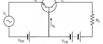
Figure 1 shows a diagram whose operation is based on the so-called. emitter follower. A transistor connected in this way tends to maintain the voltage at the emitter exactly the same as at the base (the only difference will be the voltage drop across the base-emitter junction). Thus, by fixing the base voltage using a zener diode, we obtain a fixed voltage on R1.
Next, using Ohm's law, we obtain the emitter current: Ie = Ue/R1. The emitter current practically coincides with the collector current, and therefore with the current through the LEDs.
Conventional diodes have a very weak dependence of forward voltage on current, so they can be used instead of hard-to-find low-voltage zener diodes. Here are two variants of circuits for transistors of different conductivities, in which the zener diodes are replaced by two conventional diodes VD1, VD2:
The current through the LEDs is set by selecting resistor R2. Resistor R1 is selected in such a way as to reach the linear section of the I-V characteristic of the diodes (taking into account the base current of the transistor). The supply voltage of the entire circuit must be no less than the total voltage of all LEDs plus about 2-2.5 volts on top for stable operation of the transistor.
For example, if you need to get a current of 30 mA through 3 LEDs connected in series with a forward voltage of 3.1 V, then the circuit should be powered with a voltage of at least 12 Volts. In this case, the resistor resistance should be about 20 Ohms, the dissipation power should be 18 mW. The transistor should be selected with a maximum voltage Uke not lower than the supply voltage, for example, the common S9014 (npn).
Resistance R1 will depend on the coefficient. gain of the transistor hfe and the current-voltage characteristics of the diodes. For S9014 and 1N4148 diodes, 10 kOhm will be enough.
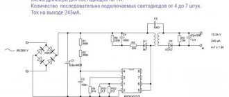
Let's use the described stabilizer to improve one of the LED lamps described in this article. The improved diagram would look like this:
This modification can significantly reduce current ripple and, consequently, the brightness of the LEDs. But the main advantage of the circuit is to normalize the operating mode of the LEDs and protect them from voltage surges during switching on. This leads to a significant extension of the life of the LED lamp.
From the oscillograms it can be seen that by adding a current stabilizer for the LED on a transistor and a zener diode to the circuit, we immediately reduced the ripple amplitude several times:
With the ratings indicated in the diagram, the power dissipated by the transistor is slightly more than 0.5 W, which makes it possible to do without a radiator. If the capacitance of the ballast capacitor is increased to 1.2 μF, then the transistor will drop ~23 Volts, and the power will be about 1 W. In this case, you cannot do without a radiator, but the pulsations will drop almost to zero.
Instead of the 2CS4544 transistor indicated in the diagram, you can take 2SC2482 or a similar one with a collector current of more than 100 mA and a permissible voltage Uke of at least 300 V (for example, the old Soviet KT940, KT969 are suitable).
The desired current, as usual, is set by resistor R*. The zener diode is designed for a voltage of 5.1 V and a power of 0.5 W. Common SMD LEDs from Chinese light bulbs are used as LEDs (or better yet, take a ready-made lamp and add the missing components to it).
Now consider the diagram presented in Figure 2 . Here it is separately:
The current sensor here is a resistor, the resistance of which is calculated using the formula 0.6/Iload. As the current through the LEDs increases, transistor VT2 begins to open more strongly, which leads to stronger blocking of transistor VT1. The current decreases. This way the output current is stabilized.
The advantage of the scheme is its simplicity. The disadvantage is a fairly large voltage drop (and therefore power) across transistor VT1. This is not critical at low currents (tens and hundreds of milliamps), however, a further increase in the current through the LEDs will require installing this transistor on a radiator.
Also, instead of a bipolar transistor, you can use a p-channel MOSFET. The circuit below is a powerful lamp using two 10-watt LEDs and a 40-watt IRF9510 in a TO-220 package (see specifications):
The current through the LEDs is set by selecting resistor R1. VT1 - any low-power. LEDs - Cree XM-L T6 10W (see specification) or similar.
Transistor VT2 and LEDs must be placed on a common radiator with an area of at least 900 cm2 (this is without forced cooling). The use of thermal paste is mandatory. The radiator fins should be thick and massive in order to remove heat as quickly as possible. Galvanized profiles for drywall, herring cans and pot lids are absolutely not suitable!!!
If such power is not needed, you can reduce the number of LEDs to one. But in this case you will have to lower the supply voltage by 3-3.5 volts. Otherwise, the power consumption will remain the same, the transistor will heat up twice as hot, and the light will be twice as bad.
To reduce the power, it would be more correct to leave both LEDs, but reduce the current, for example, to 2A - then the power will drop from 20 to 12 W, and the lifespan of the LEDs will increase many times over. And the radiator area can be reduced to 600 cm2.
Instead of IRF9510, you can take, for example, IRF9Z34N (19A, 55V) or NDP6020P (24A, 20V). See for yourself which ones are at your disposal. If you have nothing at all, it's time to buy cheap:
| Name | characteristics | price |
| IRF9510 | P-channel, 100V, 4A | 209 rub. / 10 pieces. |
| IRF9Z34N | P-channel, 55V, 19A | 124 rub. / 10 pieces. |
| NDP6020P | P-channel, 20V, 24A | 120 rub. / 10 pieces. |
| Cree XM-L T6 | 10W, 3A | 135 rub. / PC. |
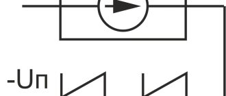
Well, the simplest current stabilizer circuit for LEDs on a field-effect transistor consists of just one transistor with a short-circuited gate and source:
Instead of KP303E, for example, BF245C or a similar one with a built-in channel is suitable. The principle of operation is similar to the diagram in Figure 1, only the ground potential is used as the reference voltage. The magnitude of the output current is determined solely by the initial drain current (taken from the datasheet) and is practically independent of the drain-to-source voltage Usi. This can be clearly seen from the output characteristic graph:
In the diagram in Figure 3, a resistor R1 is added to the source circuit, which sets some reverse gate bias and thus allows you to change the drain current (and therefore the load current).
An example of the simplest current driver for an LED is presented below:
A field-effect transistor with an insulated gate and a built-in n-type channel BSS229 is used here. The exact value of the output current will depend on the characteristics of the particular instance and the resistance R1.
These are, in general, all the ways to turn a transistor into a current stabilizer. There is also a so-called current mirror, but it is not suitable for LED lamps. So let's move on to microcircuits.
Connection diagram of the KR 142 EH5 microcircuit
Such a microcircuit serves to create a stable voltage of 5-6 V, with a current of 2-3 A. Electrode 2 of the microcircuit is connected to the metal base of the crystal. The microcircuit is fixed directly to the housing without insulating spacers. The value of the capacitance depends on the maximum current flowing through the stabilizer and at the lowest load currents - the value of the capacitance needs to be increased - the capacitor at the input must be at least 1000 μF, and at the output at least 200 μF. The operating voltage of the capacitors must be suitable for the rectifier with a reserve of 20%.
If a zener diode is connected to the electrode circuit of the microcircuit (2), the output voltage will increase to the value of the microcircuit voltage, and the zener diode voltage is added to this value.
The 200 ohm resistance is designed to increase the current flowing through the zener diode. This optimizes voltage stability. In our case, the voltage will be 5 + 4.7 = 9.7 V. Weak zener diodes are connected in a similar way. To increase the output current of the stabilizer, transistors can be used.
Type 79 microcircuits serve to equalize the negative value and are connected to the circuit in a similar way.
The KR 142 series of microcircuits includes a device with variable output voltage - KR 142EN12 A:
It should be taken into account that the pinout of the legs of 79 type microcircuits and KR 142 EH 12 differs from the standard one. This circuit, with an input voltage of 40 V, can produce a voltage of 1.2-37 V at a current of up to 1.5 A.
Current stabilizers on microcircuits
Microcircuits allow you to achieve much higher performance than transistors. Most often, to assemble a do-it-yourself current stabilizer for LEDs, they use precision thermally stable reference voltage sources (TL431, LM317 and others).
TL431
A typical current stabilizer circuit for LEDs on the TL431 looks like this:
Since the chip behaves in such a way as to maintain a fixed voltage across resistor R2 of 2.5 V, the current through this resistor will always be equal to 2.5 / R2. And if we neglect the base current, then we can assume that IRн = IR2. And the higher the gain of the transistor hfe is, the more these currents will coincide.
R1 is calculated in such a way as to ensure the minimum operating current of the microcircuit - 1 mA.
And here is an example of the practical application of TL431 in an LED lamp:
The transistor drops about 20-30 V, the power dissipation is less than 1.5 W. In addition to the 2SC4544 indicated in the diagram, you can use the more powerful BD711 or the old Soviet KT940A. Transistors in the TO-220 package do not require installation on a radiator up to powers of 1.5-2 W inclusive.
Resistor R3 serves to limit the charging pulse of the capacitor when the power is turned on. The current through the load is set by resistor R2.
The load Rn here is 90 white chip LEDs 2835 . The maximum power at a current of 60 mA is 0.2 W (24Lm), the voltage drop is 3.2 V. You can also use any other suitable LEDs, for example, SMD5050 .
To increase the service life, the power of the diodes is specially reduced by 20% (0.16 W, current 45 mA), respectively, the total power of all LEDs is 14 W.
Although I would recommend finding LEDs in exactly the same form factor (2.8x3.5mm), but with a power of 0.5 W. They will heat up less and last longer.
You can find such LEDs, as well as everything you need to assemble the circuit, using these links:
| Name | characteristics | price |
| SMD 2835 | LED, 3.3V, 0.15A, 0.5W | 67 rub. / 100 pieces. |
| 2SC4544 | NPN, 300V, 0.1A | 10 rub. / PC. |
| BD711 | NPN, 100V, 12A | 120 rub. / 10 pieces. |
| 1N4007 | 1000V, 1A | 51 rub. / 100 pieces. |
| TL431A | 36V, 100mA | 87 rub. / 100 pieces. |
Of course, the above current stabilizer circuit for 220 V LEDs can be calculated for any required current and/or other number of available LEDs.
Taking into account the permissible voltage spread of 220 Volts (see GOST 29322-2014), the rectified voltage on capacitor C1 will be in the range from 293 to 358 V, so it must be designed for a voltage of at least 400 V.
Based on the range of supply voltages, the parameters of the remaining elements of the circuit are calculated.
For example, the resistor that sets the operating mode of the DA1 microcircuit must provide a current of at least 0.5 mA at a voltage at C1 = 293 V. The maximum number of LEDs should not exceed NLED < (358 - 6) / 3.2, and the more there are, the higher the brightness of the lamp and the less power will go to nowhere (dissipate in the form of heat on transistor VT1). The maximum voltage Uke of transistor VT1 must not be lower than 358 - (ULED * NLED).
LM7805, LM7812…
Any integrated voltage stabilizer can be turned into a current stabilizer by adding just one resistor in accordance with the diagram:
You just need to take into account that, with this connection, the input voltage must be greater than the stabilization voltage of the microcircuit by a certain amount (voltage drop on the stabilizer itself). Usually it's somewhere around 2-2.5 volts. Well, of course, add voltage to the load.
Here, for example, is a specific example of a current stabilizer for LEDs based on LM7812:
The current consumption (as well as the current through the LEDs) is 300 mA. Lamp power ~10 Watt.
All parameters of the circuit are designed for 10 SMD 5730-1 LEDs with a direct voltage of 3.3 volts on each and a maximum current of 350 mA (see datasheet), bought here.
There are also very similar LEDs - SMD 5730 (without the 1 in the name). They have a power of only 0.5 W and a maximum current of 0.18 A. So don’t get confused.
Since when LEDs are connected in series, the total voltage will be equal to the sum of the voltages on each of the LEDs, the minimum supply voltage of the circuit should be: Upit = 2.5 + 12 + (3.3 x 10) = 47.5 Volts.
You can calculate the resistance and power of the resistor for other current values using the simple Regulator Design () program.
Obviously, the higher the output voltage of the stabilizer, the more heat will be generated at the current-setting resistor and, therefore, the worse the efficiency. Therefore, for our purposes, the LM7805 is better than the LM7812.
But I would recommend using an lm317 LED driver for DIY assembly (see below).
LM317
The linear current stabilizer for LEDs based on LM317 is no less effective. Typical connection diagram:
The simplest LM317 connection circuit for LEDs, which allows you to assemble a powerful lamp, consists of a rectifier with a capacitive filter, a current stabilizer and 93 SMD 5630 . MXL8-PW35-0000 (3500K, 31 Lm, 100 mA, 3.1 V, 400 mW, 5.3×3 mm) is used here.
If such a large garland of LEDs is not needed, then you will have to add a ballast resistor or capacitor to the LM317 driver to power the LEDs (to suppress excess voltage). We discussed how to do this in great detail in this article.
The disadvantage of such a current driver circuit for LEDs is that when the voltage in the network increases above 235 volts, the LM317 will be outside the design operating mode, and when it drops to ~208 volts and below, the microcircuit completely ceases to stabilize and the ripple depth will entirely depend from container C1.
Therefore, such a lamp should be used where the voltage is more or less stable. And you should not skimp on the capacity of this capacitor. The diode bridge can be taken ready-made (for example, a miniature MB6S) or assembled from suitable diodes (Uarb at least 400 V, direct current >= 100 mA). The 1N4007 mentioned above is perfect .
As you can see, the circuit is simple and does not contain any expensive components. Here are the current prices (and they will likely continue to decline):
| Name | characteristics | price |
| SMD 5630 | LED, 3.3V, 0.15A, 0.5W | 240 rub. / 1000pcs. |
| LM317 | 1.25-37V, >1.5A | 112 rub. / 10 pieces. |
| MB6S | 600V, 0.5A | 67 rub. / 20pcs. |
| 120μF, 400V | 18x30mm | 560 rub. / 10 pieces. |
Thus, by spending a total of 1000 rubles, you can collect a dozen 30-watt (!!!) non-flicker (!!!) light bulbs. And since the LEDs do not operate at full power, and the only electrolyte does not overheat, these lamps will last almost forever.
Use of microcircuits
Let's consider the properties of imported and domestic microcircuits that act instead of voltage stabilizers. They have parameters according to the table.
Foreign stabilizers of the 78... series serve to equalize the positive, and the 79... series - the negative voltage potential. Typical microcircuits with the designation L are low-power devices. They are made in small plastic TO 26 cases. More powerful stabilizers are made in a TOT type case, similar to KT 805 transistors, and are mounted on heat sinks.
Technical characteristics of the stabilizer LM338:
- Providing output voltage from 1.2 to 32 V.
- Load current up to 5 A.
- Availability of protection against possible short circuit.
- Reliable protection of the microcircuit from overheating.
- Output voltage error 0.1%.
The LM338 integrated circuit is available in two housing options: a metal TO-3 housing and a plastic TO-220 housing:
Replacement of zener diodes
Voltage stabilizers have become one of the main components of electronic equipment. Until recently, such components included:
- Transistors of various series.
- Zener diodes.
- Transformers.
The total number of stabilizer parts was considerable, especially the adjustable device. With the advent of special microcircuits, everything changed. New stabilizer ICs are manufactured for a wide voltage range, with built-in protection options.
The table contains a list of popular stabilizer microcircuits with designations.
If you need a non-standard voltage with regulation, then use 3-pin microcircuits with a voltage of 1.25 volts for the output and control pins.
A typical diagram of the operation of microcircuits at a certain voltage is shown in the figure. Capacitance C1 is not lower than 2.2 microfarads.
Adjustable microcircuits, unlike fixed devices, cannot operate without a load.
The lowest current of regulated microcircuits is 2.5-5 milliamps for weak models, and up to 10 milliamps for powerful ones. To reduce voltage ripple at elevated voltages, it is advisable to connect a 10 µF equalizing capacitor. Diode VD 1 serves as protection for the microcircuit if there is no input voltage and its output is not supplied to power. Diode VD 2 is designed to discharge capacitance C2 when the input or output circuit is closed.