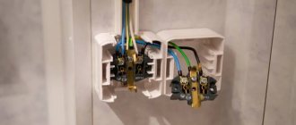
Grounding an electrical installation is a deliberate electrical connection of its housing with a grounding device.
Grounding of electrical installations is of two types: protective grounding and grounding , which have the same purpose - to protect a person from electric shock if he touches the body of the electrical installation or its other parts that are energized.
Protective grounding is a deliberate electrical connection of a part of an electrical installation to a grounding device in order to ensure electrical safety. Designed to protect a person from touching the body of an electrical installation or its other parts that are energized. The lower the resistance of the grounding device, the better. To take advantage of the benefits of grounding, you need to buy sockets with a grounding contact.
In the event of an insulation breakdown between the phase and the body of the electrical installation, its body may become energized. If a person touches the case at this time, the current passing through the person does not pose a danger, because its main part will flow through the protective grounding, which has a very low resistance. Protective grounding consists of a grounding conductor and grounding conductors.
There are two types of grounding electrodes - natural and artificial .
Natural grounding conductors include metal structures of buildings that are reliably connected to the ground.
As artificial grounding conductors, steel pipes, rods or angles, at least 2.5 m long, driven into the ground and connected to each other with steel strips or welded wire are used. Steel or copper busbars are usually used as grounding conductors connecting the ground electrode to grounding devices, which are either welded to machine bodies or connected to them with bolts. Metal enclosures of electrical machines, transformers, switchboards, and cabinets are subject to protective grounding.
Protective grounding significantly reduces the voltage that a person may be exposed to. This is explained by the fact that the grounding conductors, the grounding conductor itself and the ground have some resistance. If the insulation is damaged, the fault current flows through the electrical installation housing, the ground electrode and further along the ground to the neutral of the transformer, causing a voltage drop in their resistance, which, although less than 220 V, can be felt by a person. To reduce this voltage, it is necessary to take measures to reduce the resistance of the ground electrode relative to the ground, for example, increase the number of artificial ground electrodes.
Grounding is a deliberate electrical connection of parts of an electrical installation that are not normally energized with a solidly grounded neutral with a neutral wire. This leads to the fact that a short circuit of any of the phases to the body of the electrical installation turns into a short circuit of this phase with the neutral wire. The current in this case is significantly greater than when using protective grounding. Quick and complete shutdown of damaged equipment is the main purpose of zeroing.
A distinction is made between a neutral working conductor and a neutral protective conductor .
The neutral working conductor is used to power electrical installations and has the same insulation as other wires and a sufficient cross-section for the passage of operating current.
The neutral protective conductor is used to create a short-term short circuit current to trigger the protection and quickly disconnect the damaged electrical installation from the supply network. Steel electrical wiring pipes and neutral wires that do not have fuses or switches can be used as a neutral protective wire.
Grounding
Let's start by analyzing each system separately.
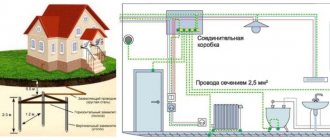
Thus, grounding is a deliberate connection of an electrical network, device or equipment with a special structure buried in the ground through a neutral conductor.
Essentially, this is a single system that connects the conductive elements of devices and equipment (for example, their housings), the wires connected to them, and the pins buried in the ground (circuit).
Due to the high resistance of the circuit, when the phase wire touches the housing in the event of a breakdown, most of the voltage goes into the ground, and although the potential will still remain on the housing, its value will be significantly reduced and not dangerous to humans.
The international standard developed by the IEC includes several grounding systems, the differences between which boil down to different types of grounding of the power source (generator or transformer substation), and grounding of open sections of the network and devices.
The standard includes three systems - TN, TT and IT.
The first letter of the index indicates the type of grounding of the source (T - “ground”), it turns out that in the first two systems the transformer substation is connected to the grounding loop.
As for the third (IT), its power source is insulated or connected to a device that provides high resistance (I - insulation).
The second letter of the index indicates the type of grounding of open sections of the network. In the TN system (N - neutral), these sections are connected to the neutral conductor of the source connected to the ground loop (solid grounding of the neutral).
To connect equipment and devices, working (N) and protective (PE) neutral conductors are used.
As for the other two systems - TT and IT, the second letter index indicates that open sections of the network, equipment and devices are grounded by their own separate circuit.
In turn, the TN system is divided into subsystems, there are three of them - TN-C, TN-S, TN-CS.
The differences between them come down to the use of different protective conductors with which consumers are connected to the source neutral.
The TN-C subsystem uses a combined conductor (PEN), which combines both the working and protective “zero”. This subsystem is already outdated, so it is not used when laying new electrical networks.
The TN-S subsystem differs in that it has working and protective “zeros” - these are different conductors. That is, an N-conductor is connected to the neutral, and a PE-conductor is connected to the grounding loop, even though they are combined at the power source.
The third subsystem – TN-CS is an intermediate link between the first two subsystems. It has a PEN conductor extending from the neutral, that is, the neutral conductors are combined, but in a certain section of the network they are separated and the working and protective “zeros” are approached separately to consumers. After separation, the protective “zero” is additionally grounded.
You can read more about grounding systems, their advantages and disadvantages here https://elektrikexpert.ru/sistemy-zazemlenij.html.
The requirements placed on grounding are quite serious. After all, it must ensure the removal of dangerous voltage from the device or equipment in the event of a breakdown.
Grounding is mandatory for networks in which the voltage is higher than 42 V AC or 110 V DC.
Therefore, during design, parts of the network and equipment that are subject to mandatory grounding must be correctly selected, and control must be exercised to ensure that the grounding circuit is not interrupted anywhere.
They also take the choice of conductors seriously; their cross-section must provide the appropriate throughput.
All requirements that are put forward to grounding systems are specified in the PUE (Electrical Installation Rules).
Here you can learn more about how to make grounding in a private house.
Zeroing
And now for zeroing. The definition of this term indicates that grounding is the deliberate connection of conductive, but not energized, elements of devices and equipment with a solidly grounded neutral (three-phase transformers), the output of a current source (single-phase transformer), the midpoint of a source supplying direct current.
That is, the housing of any device connected to the network must be additionally connected to the neutral of the power source.
For TT and IT systems, grounding is not used, since a separate circuit is used for grounding consumers.
Grounding device - what is it: will be interesting to everyone
A grounding device is a system that directly includes a ground electrode and grounding conductors, which are used to connect household appliances to a ground electrode. Grounding devices are usually divided into the following types:
- Workers to ensure uninterrupted operation of equipment;
- Protective. Ensures safe operation of devices;
- Lightning protection, allowing lightning to be discharged into a lightning rod or arrester.
Grounding is also usually divided into:
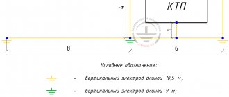
- Artificial, manufactured specifically for protection against voltage. Consists of metal rods and wires, substandard pipes, and steel angles. Experts recommend choosing steel strips or angles with a thickness of at least 4 mm, rods with a diameter of 10 mm and a length of more than 10 m;
- Natural. Such metal structures were originally made for other purposes, but can be used for voltage protection. Those who first encountered the concept of natural grounding, which is the definition of this term, will be interested. This includes reinforced concrete products, pipelines, and siege pipes. The exception is systems designed to transport gas and flammable liquids.
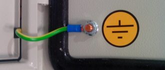
The grounding device can be in the form of a strip.
In the symbol for the grounding device, you can determine its type. The first letter shows:
- T – the power source is connected to ground directly;
- I – current-carrying elements are isolated from the ground.
The second symbol in the symbol shows:
- T – open parts that are energized must be grounded, regardless of their connection to the ground;
- N – exposed live parts are protected from the power source through a solidly grounded neutral.
The letters following the symbol with a dash after N reflect the nature of the connection and the method of arranging the conductors:
- S – PE protection of the neutral and N-working conductors is performed with separate wires;
- C – protection is provided by one wire.
Features of zeroing in an apartment
The consumer often has a question: what needs to be zeroed in the apartment, and what should not be done? Let's answer this question briefly. First, we'll tell you what not to do. Grounding in an apartment is not recommended for products that are grounded through pipes. These include metal bathtubs, sinks, faucets and other items connected to the ground through steel pipes. If these products are damaged, you may get an electric shock when you turn on the household appliance. The potentials of metal objects in the kitchen, bathroom and toilet should be equalized using grounding.
All household appliances in the apartment must be zeroed. In new homes, this problem is usually solved, since the neutral is already connected to the sockets, and all modern household appliances have a plug with a grounding contact. In older houses, electrical wiring is made using a two-wire circuit. In this case, to ground household appliances, it is necessary to install a separate wire from the apartment electrical panel, which will allow the equipment to be grounded through sockets.
In what cases is grounding necessary?
So why do you need grounding? For clarity, it is worth considering a few examples:
1. For example, there is a dishwasher in the apartment. But for some reason, at a certain moment, a phase appeared on the case, and the case was not grounded. But the neutral of the power line, which leads to the house and provides electricity, is grounded, and taps and batteries are also grounded.
If you are wearing rubber slippers, then upon contact there will be no unpleasant sensations or even the slightest blow. But if there are no shoes, and at the same time the person also grabbed the tap, and the second hand is located on the body, then it becomes a conductor of electric current, which is supplied through the body to the person, and then into the ground to the neutral, and to the substation.
2. If the dishwasher is grounded? What will happen in such a situation? If for some reason a zero appears on the housing, the current will immediately go into the ground. Even if the person is barefoot, even if he is wearing slippers, nothing will happen, the grounding has worked, there is no electric shock, everyone is safe and sound. One downside, the dishwasher will need to be repaired, but it will still be cheaper and better.
3. The washing machine in the room has broken down, and the equipment body is under voltage. In this case, if the person comes into contact with the body, he will receive an electric shock. This is why grounding is needed, then the current goes into the ground and everything is fine with the person.
The fact is that the resistance of human skin is much higher than the resistance of the wire, and then the current follows the path of least resistance, enters the ground, and the person remains intact. This is one of the simplest examples, which shows why grounding is needed in a house or other building. Without such a system, the risk of receiving an electric shock increases.
Expert opinion Evgeniy Popov Electrician, repairman
It is worth taking one more point into account, especially for the owner of a private house this is extremely important information. Even if the structure is built from natural material, the amount of electrical wiring remains the same as in a multi-story residential building, but the natural material is highly flammable. It is on this basis that a grounding system in a private home can prevent the occurrence of unpleasant situations and harmful consequences.
The most terrible event that can happen is a fire; it occurs due to a short circuit or failure of electrical equipment. That is, if doubts and questions arise about why grounding is needed in a private home, you need to realize that such a system protects not only from fires, but also prevents each family member from electric shock.
Expert opinion Evgeniy Popov Electrician, repairman
The situations can be quite scary, but they are a clear example of what negligence and disregard for safety precautions can lead to. As you can see, sometimes the consequences can really be the most serious and harmful.
What is the difference between grounding and grounding (video)
As you noticed, it is very easy to make proper grounding in the house. This protection system is safe and durable. But to create a zeroing, you need to contact the services of a specialist who will perform the installation himself. It is also necessary to periodically inspect your security system. Experts recommend using a protective grounding system only if you live in Khrushchev-era buildings. We think that after studying the article and all the differences, you understand the difference between grounding and grounding.
Let's analyze the situation with diagrams
From the point of view of the flow of electric current, there is no difference between grounding and grounding. The neutral wire in any case has electrical contact with physical ground.
Accordingly, when a phase is shorted to the housing, the same short circuit will occur and the circuit breaker will turn off. Of course, (subject to proper connection: the socket must have a third ground contact, just like an electrical appliance. For this reason, electricians, violating the requirements of the Electrical Installation Rules, often separate the ground bus from the zero contact of the input panel.
Let's imagine a situation where the neutral wire is broken for some reason:
- loss of contact due to corrosion (in old high-rise buildings this is a working situation);
- mechanical rupture of the cable due to repair work with violations of technology (unfortunately, also not uncommon);
- unauthorized intervention by a home-grown “electrician”;
- accident at the substation (only the zero bus may be disconnected).
In the diagram it looks like this:
When organizing protective grounding, the electrical circuit between the physical “ground” and the grounding contact of the electrical appliance is broken. The installation becomes defenseless. In addition, a free phase without a load can create a potential equal to the input voltage at the nearest substation. Typically this is 600 volts. You can imagine the damage that will be caused to the electrical equipment that is turned on at this moment. In this case, there is no current leakage to the physical ground, and the circuit breaker will not trip.
Imagine that at this moment you simultaneously touch a phase (a breakdown on the body of an electrical installation) and a metal object that has a physical connection with the ground (a water tap or a heating radiator). You can get electrocuted at 600 volts.
Now let's see what the difference is between grounding and neutralizing (in our diagram). If the zero bus breaks, the power to all electrical installations in this circuit will simply disappear. There will be no electric shock under any circumstances: the electrical circuit between the physical ground and the grounding contact of electrical appliances is not broken. We have already preserved our health. Now let's see what happens to electrical installations. The maximum damage is a burnt-out incandescent lamp closest to the input panel. Moreover, trouble will only occur if the voltage on the phase wire increases. The current strength will increase (according to Ohm's law), the circuit breaker will work, and perhaps other electrical appliances will not be affected.
It is for this reason that the PUE strictly prescribes: protective grounding and grounding of electrical installations must be organized independently of each other, using different lines.
For reference: Wire color coding is usually used:
- The phase is brown or white.
- The working zero is blue.
- Protective grounding is a yellow-green shell.
If you have a modern home, then grounding and grounding are carried out in accordance with the Electrical Installation Rules. This can be easily checked by looking at the input cable in the panel. In addition, you can check the correct connection yourself.
Methods of protection against dangerous potentials
The situation with damage to the phase-to-phase insulation of electrical equipment is instantly stopped by protective devices: circuit breakers or fuses. But it only indirectly poses a danger to humans.
What is more dangerous for people is a single-phase short circuit, as a result of which the housings of electric motors, electrical cabinets, and cable structures become energized.
To eliminate the risk of electric shock , it is necessary that when voltage comes into contact with the housing, a guaranteed short circuit occurs and the potential on the housing is reduced as much as possible.
The first protective effect is achieved by creating a circuit between the housing and the grounded neutral of the electrical installation. When a short circuit occurs, a current is generated that is large enough to trigger the same protective devices that operate during phase-to-phase faults. This is called protective shutdown.
To implement the second method, all potentially dangerous metal parts of electrical equipment are given ground potential. This is done by deliberately connecting them to a grounding device. The event is called protective grounding.
Grounding systems for electrical installations up to 1000 V received classification in the 7th edition of the PUE. Let's consider these systems in turn.
Grounding and grounding: the difference from each other
Fig 1
Grounding and grounding are needed to remove voltage, but this happens in different ways (Fig. 1). At the end of the article, connection diagrams TN - C, TN - S, TN - C - S are given.
The first difference is the method of current utilization
The difference is that grounding contributes to an instant shutdown of electricity when a person touches an electrical cord or device, diverting the current of a single-phase short circuit to the input panel, and grounding instantly removes dangerous voltage into the soil.
The second difference is the installation features
Installation of grounding and grounding has varying degrees of complexity.
Installing a grounding device in a private building entails certain installation work, which takes on average up to one working day. It’s quite easy to purchase ready-made modular-pin (deep) grounding kits or make them yourself from acceptable materials, strictly following the manufacturer’s instructions or grounding requirements. Directly deepening the ground electrode can be entrusted to service departments that have special equipment, or you can do it yourself, having sufficient experience and physical strength.
Regarding grounding, the installation of the grounding circuit itself does not look labor-intensive, but do not be deceived: in the absence of the proper qualifications of the electrician, a minimal mistake and ignorance can turn into disaster.
The third difference is human protection
According to the rules for the design of electrical installations (PUE), grounding can only be used for industrial installations and is not a full guarantee of safety. When a phase hits an open part of an electrical appliance or equipment, the current does not go away. Contact of two phases occurs and a short circuit occurs. The neutral is needed for rapid operation of the circuit breaker during a short circuit, but not to protect a person from electric shock. Therefore, grounding is recommended for use in production, where in the event of an accident an immediate power shutdown is required.
The fourth difference is the requirements for the professionalism of the adjuster
When zeroing is organized, in order to correctly recognize the zero points and select a method of protection, the participation of a professional electrician is extremely necessary. But most home craftsmen can competently assemble a grounding loop and immerse it in the ground.
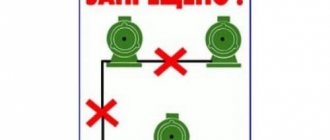
Unfortunately, in practice, quite often one can encounter the results of blatant incompetence in matters of grounding and electrical safety in general, taking into account both private adjusters and service electricians. Here are the typical and very dangerous mistakes of homemade zeroing:
Here are the typical and very dangerous mistakes of homemade zeroing:
- connecting an electrical appliance with grounding to a non-zeroing panel;
- connecting the grounding contact of the socket to the “zero” circuit breaker;
- installing a jumper in the socket connecting the neutral and protective contacts;
- performing zeroing in a two-wire system, etc.
Grounding: theory and practice
This article will address the following questions:
- Why do you need grounding (protective grounding)
- Requirements of the Electrical Installation Rules (PUE) for grounding (protective grounding)
- Methods for implementing grounding (protective grounding).
So, why is grounding still needed? A computer without it is fully functional and, as a rule, successfully performs the tasks assigned to it by the user. In general, everything is so. But... there are a number of small nuances.
Interference
Most computer power supplies have an elementary filter at the input, consisting of two capacitors, the task of which is to prevent the high-frequency component from passing through. The filter can be more advanced, including inductors (depending on the “seriousness” of the power supply manufacturer), but, in most cases, it is the filter shown in the figure. As a result, depending on the capacitance of the capacitors, we get a potential on the computer case of about 100 V relative to the phase (L) and neutral (N) wires. In other words, under certain conditions, touching the computer case can result in an electric shock. However, in rooms where the network wiring is made according to a three-phase circuit, the situation is much worse: the potential difference between computer cases sitting on different phases will already reach hundreds of volts. As a result, when connecting computers, for example, into a network, we are almost guaranteed to experience hardware damage.
By the way, those gentlemen who use surge protectors (ZIS, APC, etc.) in the absence of grounding (protective grounding), in light of the above, actually just use extension cords for $20 or more.
Electromagnetic radiation protection
In the sense of radiation that has a harmful effect on the human body. Manufacturers are constantly struggling to reduce electromagnetic radiation. They have to fight - standards and requirements are constantly becoming stricter. In general, frequencies are increasing, and radiation levels should be decreasing. So, all these activities are practically reduced to zero as a result of incorrect connection of the equipment.
Summarize. Grounding is necessary to:
- Reduce high frequency electromagnetic radiation
- Reduce emissions of noise into the electrical network
- Reduce the influence of external interference on equipment
- Ensure normal operation of equipment within the network
- Prevent human injury from capacitive current
Now let's try to figure out what requirements apply to the electrical network in general, and to grounding in particular.
The main document in this matter, of course, is the “Rules for the Construction of Electrical Installations” (PUE). All installation work and, subsequently, acceptance tests are based on the requirements of the PUE. Here it is worth noting one, in my opinion, interesting fact. The fact is that certain requirements for electrical installations are determined primarily based on the category of the room from the point of view of electrical safety. According to the PUE, there are three categories of premises:
- No increased danger
- With increased danger
- Particularly dangerous
According to this classification, apartments fall into the category of high-risk premises. But at the same time, in the PUE until 1999 they belong to the so-called residential premises where, it turns out, there is no need for grounding (grounding). And only in the seventh edition of the PUE (approved on 10/06/1999) this position was revised. Moreover: requirements were introduced that have long been used in, let’s say, advanced countries.
Some points of the rules regarding grounding will be given below, but first I would like to dwell on some concepts.
Electrical networks are divided into networks with isolated and solidly grounded neutral. In our country, to power residential premises, as a rule, networks with a solidly grounded neutral are used (the middle point of the generator is grounded), so it is more correct to say not “grounding”, but “ protective grounding ” (PE). Phase voltage Voltage between phase (L) and working neutral (N) conductors. For a 380/220 V network - 220 V. Line voltage Voltage between two phase (L) conductors. For a 380/220 V network - 380 V. Working zero (N) A conductor that, together with the phase conductor, provides power to the consumer. RCD - residual current device The operating principle of the device is based on Kirchhoff's rule (the sum of the currents is zero). The device monitors leakage currents that occur when a person touches a live wire, damage to the insulation, etc. The most common RCDs with a cutoff current of 10 mA, 30 mA and 300 mA. At the same time, in residential and public premises, as a rule, RCDs with a cut-off current of 30 mA are used. The main task of an RCD is to protect people from electric shock and fire.
Excerpts from the PUE
7.1.21.
When supplying single-phase consumers of buildings from a multiphase distribution network, it is allowed for different groups of single-phase consumers to have common N and PE conductors (five-wire network) laid directly from ASU1; combining N and PE conductors (four-wire network with PEN) is not allowed.
When supplying single-phase consumers from a multiphase supply network with branches from overhead lines, when the PEN conductor of the overhead line is common to groups of single-phase consumers powered from different phases, it is recommended to provide protective shutdown of consumers when the voltage exceeds the permissible limit, arising due to load asymmetry when the PEN breaks conductor. Disconnection must be carried out when entering the building, for example, by influencing the independent release of the input circuit breaker using a maximum voltage relay, and both phase (L) and neutral working (N) conductors must be disconnected.
When choosing devices and devices installed at the input, preference, other things being equal, should be given to devices and devices that remain operational when the voltage exceeds the permissible voltage, arising due to load asymmetry when the PEN or N conductor breaks, while their switching and other performance specifications may not be met.
In all cases, it is prohibited to have switching contact and non-contact elements in PE and PEN conductor circuits.
Connections that can be disassembled with a tool are allowed, as well as connectors specially designed for this purpose.
7.1.34.
In buildings, cables and wires with copper conductors should be used².
In residential buildings, the cross-sections of copper conductors must correspond to the calculated values, but be no less than those indicated in the table:
| Line names | Smallest cross-section of cables and wires with copper conductors, mm² |
| Group network lines | 1,5 |
| Lines from floor to apartment panels and to the settlement meter | 2,5 |
| Distribution network lines (risers) for supplying apartments | 4 |
7.1.36.
In all buildings, group network lines laid from group, floor and apartment panels to general-purpose lamps, plug sockets and stationary electrical receivers must be three-wire (phase - L, neutral working - N and neutral protective - PE conductors).
Combining zero working and zero protective conductors of different group lines is not allowed.
The neutral working and neutral protective conductors are not allowed to be connected on panels under a common contact terminal.
Conductor cross-sections must meet the requirements of clause 7.1.45.
7.1.45.
The selection of conductor cross-sections should be carried out in accordance with the requirements of the chapters of the PUE.
Single-phase two- and three-wire lines, as well as three-phase four and five-wire lines when supplying single-phase loads, must have a cross-section of zero working (N) conductors equal to the cross-section of phase conductors.
Three-phase four- and five-wire lines when supplying three-phase symmetrical loads must have a cross-section of zero working (N) conductors equal to the cross-section of phase conductors, if the phase conductors have a cross-section of up to 16 mm² for copper and 25 mm² for aluminum, and for large sections - at least 50 % cross-section of phase conductors.
The cross-section of PEN conductors must be at least the cross-section of N conductors and at least 10 mm² for copper and 16 mm² for aluminum, regardless of the cross-section of the phase conductors.
The cross-section of PE conductors must be equal to the cross-section of phase conductors with a cross-section of the latter up to 16 mm², 16 mm² with a cross-section of phase conductors from 16 to 35 mm² and 50% of the cross-section of phase conductors with larger cross-sections.
The cross-section of PE conductors not included in the cable must be at least 2.5 mm² - if there is mechanical protection and 4 mm² - if there is none.
7.1.49
In buildings with a three-wire network (see clause 7.1.36), plug sockets with a current of at least 10 A with a protective contact must be installed.
Plug sockets installed in apartments, living rooms of dormitories, as well as in rooms for children in child care institutions (kindergartens, nurseries, schools, etc.) must have a protective device that automatically closes the socket sockets when the plug is removed.
7.1.68.
In all rooms, it is necessary to connect the open conductive parts of general lighting lamps and stationary electrical receivers (electric stoves, boilers, household air conditioners, electric towels, etc.) to the neutral protective conductor.
7.1.69.
In the buildings there are metal cases of single-phase portable electrical appliances and desktop office equipment of class I in accordance with GOST 12.2.007.0.-75 “SSBT. Electrical products. General safety requirements" must be connected to the protective conductors of a three-wire group line (see clause 7.1.36).
The metal frames of partitions, doors and frames used for laying cables must be connected to the protective conductors.
7.1.72.
If the overcurrent protection device (circuit breaker, fuse) does not provide an automatic shutdown time of 0.4 s at a rated voltage of 220 V due to low values of short circuit currents and the installation (apartment) is not covered by a potential equalization system, the installation of an RCD is mandatory.
7.1.74.
In the RCD zone, the neutral working conductor should not have connections with grounded elements and the neutral protective conductor.
7.1.75.
In all cases of application, the RCD must ensure reliable switching of load circuits, taking into account possible overloads.
7.1.76.
It is recommended to use an RCD, which is a single device with a circuit breaker that provides overcurrent protection.
It is not allowed to use RCDs in group lines that do not have overcurrent protection, without an additional device that provides this protection.
When using RCDs that do not have overcurrent protection, their design verification in overcurrent modes is necessary, taking into account the protective characteristics of the higher-level device that provides overcurrent protection.
7.1.77.
In residential buildings, it is not allowed to use RCDs that automatically disconnect the consumer from the network in the event of a loss or unacceptable drop in the network voltage. In this case, the RCD must remain operational for a period of at least 5 s when the voltage drops to 50% of the rated voltage.
7.1.78.
In buildings, RCDs of type “A” can be used, which respond to both alternating and pulsating fault currents, or “AC”, which react only to alternating leakage currents.
The source of pulsating current is, for example, washing machines with speed controllers, adjustable light sources, televisions, VCRs, personal computers, etc.
7.1. 79.
In group networks feeding plug sockets, an RCD with a rated operating current of no more than 30 mA should be used. It is allowed to connect several group lines to one RCD through separate circuit breakers (fuses).
Installation of RCDs in lines supplying stationary equipment and lamps, as well as in general lighting networks, is usually not required.
7.1.80.
In residential buildings, it is recommended to install RCDs not on apartment panels; they can be installed on floor panels.
7.1.81.
The installation of RCDs is prohibited for electrical receivers, the disconnection of which could lead to situations dangerous for consumers (disabling the fire alarm, etc.).
7.1.82.
It is mandatory to install an RCD with a rated response current of no more than 30 mA for group lines that supply electrical outlets located outdoors and in particularly dangerous and high-risk areas, for example, in zone 3 of bathrooms and shower rooms in apartments and hotel rooms.
7.1.86.
If the RCD is intended for protection against electric shock and fire or only for protection against fire, then it must disconnect both the phase and neutral working conductors; overcurrent protection in the neutral working conductor is not required.
7.1.87.
At the entrance to the building, a potential equalization system must be installed by combining the following conductive parts:
- Main (main) conductor
- The main (main) grounding conductor or the main grounding clamp.
- Steel pipes, communications between buildings and between buildings.
- Metal parts of building structures, lightning protection, central heating, ventilation and air conditioning systems. Such conductive parts must be connected to each other at the entrance to the building
- It is recommended to re-install additional potential equalization systems during the transmission of electricity.
Notes:
- Input distribution device
- Until 2001 According to the existing construction backlog, the use of wires and cables with aluminum conductors is allowed.
Now we can talk about the possibility of zeroing office equipment. If your house was commissioned after 1998–1999, then, most likely, a protective zero is connected to the sockets in the apartment. If you are in doubt, you can make sure that there is a zero on the grounding contact of the socket as follows. Find the phase (using, for example, a single-pole indicator). The following is one of the ways:
- Measure the voltage between phase and neutral and then between phase and ground contact. In both cases the readings should be the same.
- Charge the E27 cartridge (regular household) with conductors of sufficient length. Screw an incandescent lamp with a power of at least 100 W into it. Insert one wire into the phase socket, with the second touch the working and protective zeros alternately ( ATTENTION! If there is an RCD, it will cut off, which confirms the presence of a protective zero). The lamp should burn equally brightly and evenly.
It is also advisable to trace the outgoing ends from the distribution panel to your apartment. As a rule, a group for lighting (L+N), a group for sockets (L+N+PE), and a group for electric stove (L+N+PE) are started. That is, you should have 3 ends going to the sockets, and N and PE, according to the PUE, should not fit under one bolt.
Below we will consider the option of independently connecting the protective zero.
ATTENTION! Work in the switchgear can only be carried out by persons from the electrical technical personnel of the service enterprise with an electrical safety clearance group of at least III.
If you have no experience, I categorically do not recommend installing a protective neutral in an organization where all three phases are connected to the sockets: if you use one working zero and accidentally damage or weaken it during installation work, you get two phases at the input of the equipment. I can only say that in this situation, even the varistors of network filters burn out (melt).
For a home network, you will need a copper wire of the appropriate length and a cross-section of at least 1.5 mm² (the larger the better - for example, I used a wire with a cross-section of 4 mm²) and, of course, a socket with a grounding contact. The box, plinth, bracket is a matter of aesthetics. One end of the wire is inserted under the free bolt of the distribution board bus connected to the panel body, and the other - to the grounding contact of the socket. It is not allowed to place N and PE conductors under the same bolt. If there is an RCD in the panel, the PE conductor should not be taken into account (it should be bolted onto the panel body) and should not have contact with the N conductor anywhere on the line (otherwise the RCD will be triggered).
Regarding the issue of grounding to the battery (water supply), I do not recommend it. Theoretically, there should be a potential equalization system somewhere in the basement (the pipes themselves laid in the ground are a natural grounding device), but in fact, a potential different from zero may suddenly appear on the battery. For example, your upstairs neighbor uses it as a working zero due to the burnout of the conductor in the strobe.
And one more point regarding installation. The network in apartments is currently carried out using aluminum wire. If you need to extend the ends (for example, to move a socket) and use copper wire, never twist copper with aluminum - a galvanic couple occurs, the metal at the point of contact is actively destroyed, the transition resistance increases, burning occurs, which ultimately can lead to a fire . Copper and aluminum conductors are connected to each other either through an adapter block or through adapter washers. It is allowed to use steel washers as an adapter.
Grounding
Now the main question is, what is the difference between grounding and grounding? It's all about installing additional protective devices. To achieve safe operation of household electrical appliances, it is necessary to install either an RCD (residual current device) or differentiated circuit breakers into the distribution board. Both types of devices have in their design a special working element that equalizes the current strength in the phase and neutral wires.
Ground connection diagram
- If the network and household appliances operate in normal mode, then the currents in different circuits are the same in magnitude, but flow in different directions: in phase into the apartment, in zero out of it. That is, the entire system is balanced, so household appliances work well according to their nominal parameters.
- If there is an insulation break anywhere in the electrical system (wires, household appliances, machines, etc.), the current begins to flow to the ground. In this case, this current passes past the zero conductor. That is, grounding ceases to work. An imbalance occurs in the working body of an RCD or a differentiated machine. As soon as the violation begins, a protective device is immediately activated, which disconnects the contacts. Electricity is no longer supplied to the system.
And one more point that concerns protective grounding and grounding. Experts recommend installing a separate circuit in which the so-called PE conductor is mounted. It is specially taken outside the distribution board and installed near the socket in the socket. In this case, the socket must be three-phase: phase, neutral and ground. The conductor is connected to ground.
Please note that when plugged into a socket, the plug from a household appliance first touches the ground, and then the two main phases. The same thing happens at the moment of switching off: first the phases are output, then lastly the ground
This is a guarantee that in the event of a short circuit in the household electrical appliance itself, the entire system will not fail due to the increased current in it.
Typically, the RCD is installed in the distribution panel after the main input circuit breaker. It is necessary to take into account the fact that the residual current device does not protect the electrical network from wire short circuits. The likelihood that this device itself will fail for this reason is very high.
Therefore, it is so important to adjust the parameters of the introductory machine with the parameters of the RCD itself. The best option is to install another machine in front of the device, which will be identical in parameters to the protection
By the way, it should be noted that the RCD with a machine for it is, in fact, an ordinary differential machine. The latter costs more than a protective device, but is much more compact in size.
Now you can understand the differences between grounding and grounding.
What is zeroing: principle of operation and device
Grounding is installed according to a different principle. But to sort this out, let’s look at what a solidly grounded neutral is. 3 phases arrive at the transformer substation via power lines. The own grounding, mounted around, is a solidly grounded neutral, which goes to residential buildings from the substation, along with the phase wires.
Zeroing is done like this. Wiring is made in the distribution board, the solidly grounded neutral (PEN) coming from the transformer substations is broken in front of the input circuit breaker into a zero (N), going to the apartment, and what can be considered ground (PE). In fact, in essence, this will remain a solidly grounded neutral, which will be used for grounding. Worker N is prohibited from zeroing the equipment - this is dangerous to life. If everything is done correctly, then when the body of the switched-on device comes into contact with a live, bare wire, a short circuit occurs, after which the machine is triggered.
The simplest scheme for zeroing an apartment electrical network
Expert opinion Igor Marmazov ES, EM, EO design engineer (power supply, electrical equipment, interior lighting) ASP North-West LLC
“Protective grounding is a system that is installed to instantly trigger the automation when voltage appears on the device body and completely shuts off the power.”
Only a complete understanding of what grounding and grounding are, what their features are, will make it possible to implement the type of protection in an apartment or house that will be effective and safe.
Circuit design
Components
The previously mentioned grounding resistance (Rз) of the circuit is the main parameter controlled at all stages of its operation and determines the effectiveness of its use. This value must be so small as to provide a free path for the emergency current tending to flow into the ground.
Note! The most important factor that has a decisive influence on the value of grounding resistance is the quality and condition of the soil at the site of the installation. Based on this, the charger in question or the ground loop of the charge circuit (which in our case is the same thing) must have a design that meets the following requirements:
Based on this, the charger in question or the ground loop of the charge circuit (which in our case is the same thing) must have a design that meets the following requirements:
- It must include a set of metal rods or pins with a length of at least 2 meters and a diameter of 10 to 25 millimeters;
- They are connected to each other (necessarily for welding) by plates of the same metal into a structure of a certain shape, forming a so-called “grounding conductor”;
- In addition, the device includes a supply copper busbar (also called electrical) with a cross-section determined by the type of equipment being protected and the magnitude of the drain current (see the table in the figure below).
Tire Section Table
These component devices are necessary to connect the elements of the protected equipment with the descent (copper busbar).
Differences in device location
According to the provisions of the PUE, the protective circuit can have both external and internal design, and each of them is subject to special requirements. The latter establishes not only the permissible resistance of the ground loop, but also stipulates the conditions for measuring this parameter in each particular case (outside and inside the object).
When dividing grounding systems according to their location, it should be remembered that only for external structures the question of how the grounding resistance is normalized is correct, since it is usually absent indoors. Internal structures are characterized by wiring of electrical busbars along the entire perimeter of the premises, to which grounded parts of equipment and devices are connected through flexible copper conductors.
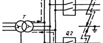
For structural elements grounded outside the facility, the concept of re-grounding resistance is introduced, which appeared as a result of the special organization of protection at the substation. The fact is that when forming a neutral protective conductor or a working conductor combined with it at the supply station, the neutral point of the equipment (step-down transformer, in particular) is already grounded once.
Therefore, when another local grounding is made at the opposite end of the same wire (usually a PEN or PE bus connected directly to the consumer panel), it can rightfully be called repeated. The organization of this type of protection is shown in the figure below.
Re-grounding
Important! The presence of local or repeated grounding allows you to insure yourself in case of damage to the protective neutral wire PEN (PE - in the TN-CS power supply system). Such a malfunction is usually found in technical literature under the name “zero burnout”
Such a malfunction is usually found in technical literature under the name “zero burnout.”
What is the difference between grounding and grounding?
This question may arise from the reader against the background of the previous information. After all, essentially the same grounding comes from the TP. Let's explain. The fourth wire that comes into the house can no longer be a grounding wire, because it is used by other residents as a neutral wire. For example, let's take a situation in which we decided that zero and grounding are the same thing. We make the wiring directly in the socket, throwing a jumper between the zero and the ground contact and calm down - we are protected.
Whatever the case! The exposed wire is close to the body of the device, but has not yet touched it, but a magnetic field has already arisen and the current-carrying conductor begins to heat up. But at the same time, the neutral wire heats up even more at the weak connection. The insulation of the current-carrying conductor burns out, it touches the body, annealing the zero. That's it, there is no light in the apartment, but the machine did not work. Now the device body is under phase voltage. What will happen if you touch it? The voltage will pass through a person into the ground along the path of least resistance, causing maximum damage to the conductor (it’s clear who we’re talking about).
Grounding like this could kill someone one day
Scheme of work
As mentioned above, grounding is based on provoking a short circuit after a phase hits the metal body of the electrical installation connected to zero. As the current increases, a protective mechanism is activated that cuts off the power supply.
According to the standards of the Electrical Installation Rules, in the event of a violation of the integrity of the line, it must be turned off automatically. The shutdown time is regulated - 0.4 seconds (for 380/220V networks). To disconnect, special conductors are used. For example, in the case of single-phase wiring, the third core of the cable is used.
For correct zeroing, it is important that the phase-zero loop has low resistance. This ensures that the protection is activated within the required period of time.
Organization of grounding requires high qualifications, therefore such work should be performed only by qualified electricians.
The diagram below shows how the system works:
Checking the effectiveness of zeroing
To check how effective grounding is, you need to measure the resistance of the phase-zero loop at the point furthest from the power source. This will make it possible to check the protection in the event of exposure to current on the housing.
Resistance is measured using specialized equipment. The measuring instruments are equipped with two probes. One probe is directed to the phase, the second to the neutralized electrical installation.
Based on the measurement results, the resistance level in the phase and zero loop is established. With the result obtained, the single-phase fault current is calculated using Ohm's law. The calculated value of the single-phase fault current must be equal to or greater than the trip current of the protective equipment.
Let's assume that a circuit breaker is connected to protect the electrical circuit from overloads and short circuits. The operating current is 100 Amperes. According to the measurement results, the resistance of the phase and zero loop is 2 Ohms, and the phase voltage in the network is 220 Volts. We calculate the single-phase fault current based on Ohm's law:
I = U/R = 220 Volts/2 Ohms = 110 Amps.
Since the calculated short-circuit current exceeds the instantaneous operation current of the circuit breaker, we conclude that the protective grounding is effective. Otherwise, it would be necessary to replace the circuit breaker with a device with a lower operating current. Another solution to the problem is to reduce the resistance of the phase-zero loop.
Often, when carrying out calculations, the operating current of the machine is multiplied by the reliability factor (KN) or safety factor. The reason is that the cutoff is not always equal to the specified indicator, that is, a certain error is possible. Therefore, using the coefficient allows you to obtain a more reliable result. For old equipment, Kn ranges from 1.25 to 1.4. For new equipment, a coefficient of 1.1 is used, since such machines operate with greater accuracy.
Difference between grounding and grounding
There are differences between grounding and grounding:
- In the case of grounding, the excess current and the voltage that appears on the housing are redirected to the ground. The principle of zeroing is based on zeroing on the shield.
- Grounding is more effective in terms of protecting people from electric shock.
- Grounding is based on a rapid and significant reduction in voltage. Nevertheless, some (no longer dangerous) tension remains.
- Grounding consists of creating a connection between metal parts in which there is no tension. The principle of grounding is based on the deliberate creation of a short circuit when insulation breaks down or current enters non-current-carrying parts of electrical installations. As soon as a short circuit occurs, the circuit breaker comes into play, fuses blow, or other protective measures are activated.
- Grounding is most often used on lines with an isolated neutral in IT and TT systems in three-phase networks, where the voltage does not exceed a thousand volts. Grounding is used at voltages of more than a thousand volts with a neutral in any mode. Grounding is used in solidly grounded neutrals.
- When zeroing, all elements of electrical appliances that are not energized in the standard mode are connected to zero. If a phase accidentally touches zeroed elements, the current increases sharply and the electrical equipment is switched off.
- Grounding does not depend on the phases of electrical appliances. To organize zeroing, strict connection conditions must be observed.
- In modern houses, grounding is rarely used. However, this method of protection is still found in multi-storey buildings, where for some reason it is not possible to organize reliable grounding. At enterprises where there are increased electrical safety standards, the main method of protection is grounding.
Note! To correctly determine the zero points and select the method of protection, you will need the help of a qualified electrician. You can make grounding, assemble circuit elements and install it in the ground with your own hands.
How does grounding work?
Safe use of household devices by connecting the housing to the protective zero, ensuring the operation of “Residual current equipment” or circuit breakers. The latter have a working mechanism that compares the currents entering the phase wire into the house and leaving the working conductor.
If the power transmission mode is normal, the currents are equal and also opposite in direction. Because of this, their interaction is balanced and balanced, ensuring proper operation with normal parameters.
When an insulation fault occurs in one or more places in a circuit, current flows through that area and is directed toward ground. No current passes through the working zero conductor. A current disturbance occurs in the mechanism, which leads to the shutdown of the protective element and the connections of the protective mechanism are disconnected, preventing the flow of current through the circuit. The end of the voltage supply occurs in a millisecond.
When connecting the ground to a household device, use a PE conductor. It is led out of the distribution panel along a special path to the outlet, which is equipped with a special outlet. Such protection does not prevent the occurrence of a short circuit, so an automated switch is installed on it. Buying it will cost several thousand rubles and takes up a lot of space.
Features of the land:
- If the metal tap of the household appliance and the phase are connected, therefore no voltage occurs. If the wire insulation is broken, the person who touches it will receive a serious electric shock. By using grounding you can prevent this from happening.
- Various currents flow to the grounding conductor, preventing danger to humans.
- When voltage occurs, it is supplied to the heating radiator, which poses an even greater danger. Because of this, all the batteries turn into conductors. By setting ground, all current exits through the conductor.