Designed to protect people working on disconnected live parts of equipment or electrical installations from electric shock in the event of an erroneous supply of voltage to the disconnected area or when induced voltage appears on it. Portable grounding is used in those parts of the electrical installation that do not have stationary grounding blades.
The protective effect of portable grounding or stationary grounding blades is that they do not allow voltage to appear beyond the place of their installation. When voltage is applied to a grounded and shorted section, a short circuit occurs. Thanks to this, the voltage at the point of the short circuit is reduced to almost zero and no voltage will flow to the current-carrying parts behind the grounding. In addition, the protection will work and turn off the voltage source.
The lack of installed portable grounding on live parts of the electrical installation being serviced, violation of the regulations for their use, the use of low-quality grounding or that does not comply with current technical standards have repeatedly led to severe, including fatal, electrical injuries.
Portable grounding device
Portable grounding consists of: conductors for grounding and short-circuiting between themselves current-carrying parts of different phases of an electrical installation and clamps for connecting conductors to the grounding wiring and to live parts. Grounding and short-circuiting conductors are made of copper stranded flexible bare wire. Portable groundings are carried out both three-phase (for short-circuiting all three phases and grounding with a common grounding conductor) and single-phase (for grounding the current-carrying parts of each phase separately). Single-phase portable grounding connections are used in electrical installations with voltages above 110 kV, since there the distances between phases are large and the short-circuiting conductors are excessively long and heavy. According to the method of application, portable groundings are divided into groundings for use on overhead power lines (OL) and in switchgears (RU).
What is an RCD?
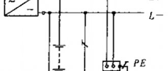
If you are not satisfied with these methods of ensuring electrical safety, and it is not possible to install grounding, then there is another powerful tool that can reliably protect you from the traumatic effects of electric current. This is a residual current device, better known by the abbreviation RCD. It compares the phase current with the zero current. If the current in the phase wire is at least slightly greater than the current in the neutral wire, then there is a leak and part of the current returns to the substation through the ground. In this case, the RCD will instantly disconnect the line and if the cause of the leak is a person who has come under voltage and through whom the current flows into the ground, then nothing bad will happen to him. The RCD will have time to turn off the current before it has time to harm a person. Although electrical accidents in the home are very rare, you should not skimp on such devices. After all, human life is too precious to neglect such a danger.
Grounding for overhead lines
Portable grounding for overhead lines is designed to protect workers from high voltage damage by grounding a section of overhead lines from erroneously supplied or induced voltage from adjacent lines. Grounding connections for overhead lines consist of phase clamps or clamps, short-circuiting/grounding flexible conductors, insulating grounding rods (insulating ropes), as well as grounding clamps. For various types of work, portable grounding can be produced as single-phase or three-phase (for 0.4 kV overhead lines - five-phase), and also, in some cases, the number of phases can be more than 3.
On overhead lines, two main types of grounding are used - with a solid insulating rod and a composite rod consisting of metal conductive links and an insulating part. Grounding connections for overhead lines with a solid insulating rod are universal and most common. Mainly used when working from towers and lifts, as well as when using claws and manholes. Grounding connections with metal conductive links are used on overhead lines of high voltage classes when working from a crossarm. Recently, such groundings have begun to be used on 6-10 kV lines for installation from the ground. The use of metal conductive links is caused by the need to reduce the weight of the grounding as a whole with a long rod length. The combination of a structural and conductive grounding element makes it possible to reduce the weight load on the worker’s hands to an acceptable value. For this reason, grounding for overhead lines with metal conductive links, as a rule, is made single-phase.
Grounding for switchgear
Portable grounding for switchgear is intended to protect workers from high voltage damage by grounding a section of the switchgear from erroneously supplied or induced voltage from neighboring circuits. Having an identical design, grounding connections for switchgear differ in the method of installation in the switchgear: phase clamps are installed on conductive busbars, on special ball or cylindrical tips, or instead of fuses. Various locations for installing grounding in the switchgear are determined by the work regulations and the design features of the electrical installations being serviced.
Requirements for portable grounding
The main requirement for portable groundings is their thermal and dynamic resistance to short circuit current. The clamps with which conductors are secured to live parts must be such that they cannot be torn off by dynamic forces. In addition, the clamps must provide very reliable contact. Otherwise, if there is a short circuit, they will overheat and burn.
When short-circuit current flows, the short-circuiting conductors become very hot. Therefore, they must be sufficiently thermally stable to remain intact during the tripping time of the short-circuit protection relay. It must be borne in mind that copper melts at a temperature of 1083 ° C. The thermal stability of conductors is important, because when the conductors are heated and broken, the operating voltage of the electrical installation may appear at their ends. The minimum cross-section for reasons of mechanical strength is accepted: for electrical installations with voltages above 1000 V - 25 mm2 and for electrical installations with voltages below 1000 V - 16 mm2. Conductors smaller than these cross-sections cannot be used. For electrical installations with a voltage of 6 - 10 kV with significant short circuit currents, portable grounding conductors are of a very large cross-section (120 - 185 mm2), heavy and difficult to use. In such cases, it is allowed to use two or more portable grounding connections, installing them in parallel, one directly next to the other.
Sections of grounding conductors in electrical installations above 1000 V
| Grounding conductor cross-section, mm2 | Maximum permissible short-circuit current, kA with duration of main relay protection, s | ||
| 0,5 | 1,0 | 3,0 | |
| 25 | 10 | 7 | 4 |
| 50 | 20 | 14 | 8 |
| 70 | 25 | 18 | 10 |
| 90 | 35 | 25 | 15 |
| 2x50 | 40 | 28 | 16 |
| 2x95 | 70 | 50 | 30 |
The cross-section of portable grounding conductors is calculated using a simplified formula:
S = (Iset √tph) / 272,
where Ist is the steady-state short-circuit current, A,
tf — fictitious time, sec.
For practical purposes, the value of tf can be taken equal to the time delay of the main relay protection of the connection of the electrical installation, the switch of which must disconnect the short circuit at the portable grounding point. In order not to make portable grounding connections of different cross-sections for switchgear of the same voltage, the longest one is usually taken as the design time delay.
In networks with a grounded neutral, the cross-section of the conductors is calculated based on the single-phase short circuit current, while in a system with an isolated neutral, it is sufficient to ensure thermal stability during a two-phase short circuit. It is not allowed to use insulated wire for grounding conductors, because insulation does not allow timely detection of damage to the conductor cores, which reduces its design cross-section and can lead to flashover by short circuit current.
Portable grounding
The design of the clamps for connecting conductors must ensure the possibility of their reliable and durable fastening to live parts using a special rod for installing grounding. The short-circuiting conductors are connected directly to the terminals without adapter lugs. This requirement is explained by the fact that the tips may contain unsatisfactory contacts that are difficult to detect, but which may burn out when a short circuit current flows. The connection of the three-phase grounding short-circuiting conductors to each other and to the grounding conductor is carried out firmly and reliably by crimping or welding. A bolted connection can also be made, but in addition to the bolts, the connection must be soldered with hard solder. Connection by soldering alone is not allowed, since the heating of the groundings during the flow of current can reach hundreds of degrees, at which point the solder will melt and the connection will be broken.
Tools and materials
To make a homemade ground electrode, galvanized metal must be used - a pipe, angle or rod.
The finished ground electrodes are made of carved copper-plated pins connected by brass couplings. The connection between the pin and the ground wire is made using a stainless steel clamp and a special paste. Grounding conductors must not be painted or lubricated.
When choosing the cross-section of rolled products, the effect of corrosion is taken into account, as a result of which the cross-section is reduced. Minimum rolled sections:
- For galvanized rod - 6 mm;
- For rectangular rolled products - 48 mm2;
- For a metal rod - 10 mm.
The pins are connected to each other with a corner, strip or wire. With their help, grounding is supplied to the electrical panel. For connecting bars the dimensions are:
- Rod diameter - 5 mm;
- The size of the rectangular profile is 24 mm2.
The cross-section of the phase wire must be greater than the cross-section of the grounding wire in the room. Such conductors are subject to certain requirements affecting the diameter of the cores:
- Aluminum without insulation - 6 mm;
- Copper without insulation - 4 mm;
- Copper insulated - 1.5 mm;
- Aluminum insulated - 2.5 mm.
The grounding conductors are connected using grounding bars made of electrical bronze. All parts of the shield according to the TT diagram are attached to the wall of the box.
Installation of grounding on a home-made overhead line is carried out using a sledgehammer, with which the grounding conductor is driven into the ground. Driving in factory parts is done using a jackhammer. In both methods of grounding installation, it is advisable to use a stepladder. Manual welding is used for welding rolled ferrous metal.
Grounding locations
Portable grounding must be applied to the current-carrying parts of all phases of the electrical installation section that is disconnected for work on all sides from which voltage can be supplied, including due to reverse transformation. It is sufficient to apply one ground connection on each side. These grounds can be separated from live parts or equipment on which work is performed by disconnected disconnectors, circuit breakers, circuit breakers, or removed fuses.
The application of grounding directly to the current-carrying parts on which work is performed is required when these parts may be under induced voltage (potential) or voltage from an extraneous source of dangerous magnitude may be applied to them. Places for applying grounding must be selected so that the grounding is separated by a visible gap from live parts that are energized. When using portable groundings, their installation sites must be at such a distance from live parts that remain energized that the application of groundings is safe. When working on busbars, at least one grounding must be applied to them. In closed switchgears, portable grounding connections must be applied to live parts in designated locations. These areas must be cleared of paint and bordered with black stripes.
In electrical installations whose design is such that applying grounding is dangerous or impossible, additional safety measures must be taken when preparing the workplace to prevent accidental supply of voltage to the work site. These measures include:
- locking the disconnector drive with a padlock
- enclosing the knives or upper contacts of the specified devices with rubber caps or hard linings made of insulating material
How to properly install portable grounding
It is prohibited to use any conductors for grounding that are not intended for this purpose, as well as to connect grounding connections by twisting them. Portable grounding connections are installed on live parts on all sides, from where voltage can be supplied to the area that is disconnected for work. If the area where work is being carried out is divided by a switching device (switch, disconnector) into parts or, during the work, the integrity of the current-carrying parts of the area is violated (part of the wires are removed, etc.), then if there is a danger of induced voltage from neighboring lines appearing on each individual The area must be grounded.
Grounding is installed using an insulating rod, which is integral with the grounding or is used for alternate operation with the terminals of all phases. First, the grounding conductor is connected to the grounding wiring or grounded structure. Then, after checking the absence of voltage on the current-carrying parts with a voltage indicator using a rod, the grounding clamps are alternately applied to the current-carrying parts of all phases. If the rod is not equipped to secure the clamps, fastening can be done manually while wearing dielectric gloves.
When installing grounding in switchgear, operations should be performed from the floor or ground, or from a ladder, without climbing onto equipment that has not yet been grounded. If it is impossible to install and secure grounding connections on the busbars from the ground or a ladder in an open switchgear, then climbing onto the equipment (transformer, switch) for this purpose is possible only after a complete check of the absence of voltage at all inputs. Climbing onto the structure of a 35 kV or higher disconnector, which is energized on one side, is unacceptable under any circumstances. Because the person installing the ground may find himself dangerously close to live parts that remain energized. During such operations, electric shocks occurred. It must be taken into account that the induced voltage is absent on the current-carrying part only when grounding is connected to it. Therefore, even after removing the charge from the live part or after removing the grounding, it is unacceptable to touch ungrounded live parts without protective equipment. All operations on installation and removal of portable grounding are carried out using dielectric gloves.
Installation algorithm
Grounding is carried out from the side of the current-carrying conductors, from where voltage is supplied. Between the connection point and the place where the ground needs to be laid, there should be no transforming elements with galvanic isolation, which include voltage multipliers, stabilizers and transformers.
The operator who configures and installs temporary equipment must wear protective clothing. This includes a transparent face mask, mittens, insulating boots, and a dielectric foot mat. Working without protection is prohibited.
All work is carried out in strictly the following sequence:
- Attaching a common or central clamp to a grounding bus. It must be valid and verified.
- Using a tester or an indicator screwdriver, check the absence of voltage on the current-carrying core.
The work must be carried out by at least two specialists. This allows, in the event of an electric shock, to turn off the power supply, provide first aid to the victim and call a doctor. Installation and connection should only be carried out by highly qualified professionals and sufficient experience.
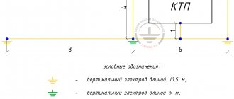
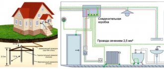
If work is carried out on an ungrounded (standard) electrical installation, it is necessary to create a temporary grounding loop. For this purpose, the same triangle is organized in accordance with the rules for organizing a protective grounding system. A portable grounding connection is connected to it.
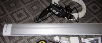
The ground electrode is organized using metal pins, profiles (they are driven in with a sledgehammer), or gimlets. Such devices must have a device for removing them from the ground after completion of work.
Another option for easy installation is a return hammer ground electrode. With its help, you can easily immerse the rod in the ground and remove it back.
Installation of portable grounding on a temporary circuit is carried out according to the same rules as on a stationary protective grounding bus.
How to properly remove portable grounding
Removal of grounding should be done in the reverse order using a rod and dielectric gloves. That is, first remove it from live parts and then disconnect it from grounding devices. If the nature of work in electrical circuits requires removal of grounding (for example, when checking insulation with meggers), temporary removal of groundings that interfere with the work is allowed. In this case, the place of work must be prepared in full compliance with the above requirements. And only for the duration of the work can those groundings be removed, in the presence of which the work cannot be completed.
In electrical installations with voltages above 110 kV, grounding should be removed using rods. Even if at the installation site it is possible to perform the operation without a rod. In electrical installations with voltages of 110 kV and below, it is permissible to use only dielectric gloves. Moreover, only in cases where to remove the grounding it is not necessary to climb onto the disconnector structures. Turning on and off grounding knives, applying and removing portable groundings must be taken into account according to the operational scheme, in the operational log and in the work order.
Increased security
The procedure for installing portable grounding connections in electrical installations should begin with enhancing safety. The possibility of accidental voltage supply to the sections being repaired is eliminated.
The equipment to be switched off and the drives in the protective blocks must be locked; at the point where the disconnect switches are connected, the contacts must be insulated using special caps.
These measures and other procedures to ensure safe operation must be described in the local instructions. If it is not possible to fully comply with safety requirements, the supply line of the switchgear is turned off.
When removing and applying portable grounding, the employee must strictly follow the above procedure. Even if voltage is mistakenly supplied to the network, the worker will not receive an electric shock when the grounding cable clamp is connected.
Thus, a portable grounding device helps to protect electricians when carrying out repair work. You can buy it at an industrial goods store, paying attention to the main technical characteristics.