The organization of protective grounding on the consumer side is a mandatory procedure regulated by current regulations and state standards (GOST). The main documents that define the procedure for the work carried out and contain the basic requirements for grounding are the Rules for the Construction of Electrical Installations (PUE) and PTEEP. The relevant provisions of these rules also stipulate the conditions for organizing and conducting maintenance of grounding systems (including their electrical tests).
Requirements for grounding devices (GD)
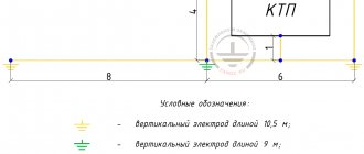
According to the requirements of the regulations, any existing electrical installations must be protected by a special grounding circuit (GC), which includes such a mandatory component as a ground electrode.
The latter is a prefabricated structure made of metal elements that provide reliable contact with the ground and facilitate the spread of current into it.
This structure (part of the grounding), as a rule, is made of individual conductive elements (metal rods, pipe blanks or standard profiles) immersed in the ground to a certain depth.
The rules for arranging such structures assume that only steel or copper can be used for their manufacture, but not aluminum or other metals.
The same rules also stipulate possible design options for the ground electrode system, and also establish compliance with their indicators standardized according to the PUE.
Conditions for a quality connection
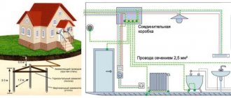
To install a high-quality grounding circuit in a city house apartment, first of all, it is necessary to completely replace the old wiring with a three-core cable, in which the phase and neutral working conductors are supplemented with a PE grounding bus.
Only with such a separate wire will it be possible to organize a circuit for the emergency current to flow from the body of the damaged device through the ground loop into the ground.
When replacing wiring in an apartment, do not try to save on consumables and choose a high-quality three-core copper cable of the required cross-section (brand NUM or VVG, for example).
Next, you should assemble a team of interested residents of the entrance who want to connect their apartments to the collective grounding system and, if necessary, obtain permission from housing and communal services to arrange grounding.
It is best to place the contour on the back side of the house (not on the front part). To distribute the grounding conductor throughout the apartments and connect it on the consumer side, a copper busbar with a cross-section no less than that of the PEN conductor included in the cable supplied to the house is used.
In the figure above, you can see how grounding is organized by connecting the PE conductor of the electrical wiring with the elements of the ground electrode, which in this situation performs the function of re-grounding.
Resistance
One of the main indicators of the effectiveness of grounding is the electrical resistance of the entire system as a whole, which, according to clause 7.1.101 of the PUE (seventh edition of 2016), should not exceed the following values:
- for transformer substations 6-35 kilovolts and supply generators - no more than 4 Ohms;
- for residential buildings with supply voltages of 220 or 380 Volts - no more than 30 Ohms.
Grounding resistance can be adjusted by special methods involving the following operations:
- increasing the effective contact area of the metal structure with the soil due to the inclusion of the required number of additional elements in its composition;
- increasing the specific conductivity in the area where the grounding loop is placed by adding salt compounds dissolved in water to the soil;
- reducing the length of sections of routes along which grounding conductors are laid from the protected equipment and the distribution cabinet with the main switch towards the charger.
In addition, the protective properties of the grounding system also depend on the characteristics of the soil at the site where the ground electrode is installed.
Technical requirements for the organization of grounding of electrical installations
Ultrasound is used to protect people and equipment from the destructive effects of electric current. Safety is ensured by connecting the protected enclosures of electrical installations to the ground. Work on organizing grounding networks is regulated by the provisions of GOST 12.1.030-81, according to which protective grounding of an electrical installation should be carried out under the following parameters:
- at rated voltage values of 380 V or more alternating current and more than 440 V or more direct current - at any values;
- at rated voltage values of 42-380 V AC 110-440 V. For work associated with increased danger.
A properly organized grounding system for electrical installations can neutralize excess potential of any power and protect people, equipment and buildings from the effects of electric current, whether surges caused by turning on or off power equipment or lightning.
The operating principle is based on the difference in resistance of the human body and ultrasound. Excess potential is diverted in the direction of a lower indicator, i.e. towards the protective circuit.
Selection of natural ground electrodes
According to the rules for the construction of electrical installations, their housings must be connected to artificial or natural grounding conductors. The following metal objects are used as natural ones:
- frames of underground metal structures having direct contact with the ground;
- protective covers for cables laid underground;
- metal pipes, with the exception of gas and oil pipelines;
- railway rails.
Contact of the object with the natural ground electrode must be made in at least two places. The advantages of this method are simplicity, efficiency and cost reduction in organizing an electrical safety system.
The following objects cannot be selected as natural grounding conductors:
- pipelines of flammable and explosive gases and liquids;
- pipes coated with anti-corrosion insulation;
- sewer pipelines;
- central heating pipes.
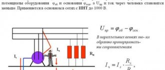
Current flow resistance
Grounding works according to the following principle: the current flowing into the ground through the fault point first passes to the body of the electrical installation and from it through the ultrasound into the ground. Obviously, when organizing grounding networks up to 1000 Volts, it is important to create a chain that ensures excess charge flows into the ground.
Grounding resistance values for networks for various purposes:
| Purpose of the network | Maximum resistance value, Ohm |
| Private houses 220, 380 Volt | 30 |
| Industrial equipment | 4 |
| Current source at voltages of 660, 380 and 220 Volts | 2, 4, 8 |
| Private house when connecting a gas pipeline | 10 |
| Communication line protection devices | 2 (less often 4) |
| Telecommunications equipment | 2 or 4 |
To obtain the resistance indicators established by the standards, standard procedures should be followed:
- Increase the area of contact between the parts of the grounding device and the ground.
- Ensure high-quality contact between the device elements and the connecting busbars.
- Strengthen soil conductivity by moistening or increasing its salinity.
To monitor compliance of resistance with prescribed standards, its level should be checked at least once every six years.
Ultrasound operation in case of violation of protective insulation of electrical equipment
Violation of the integrity of the protective insulation often leads to a phase short circuit to the housing. Further developments depend on the quality of the electrical safety system. The following options are possible:
- There is no grounding, the residual current device is not installed. The most unfavorable situation. When you touch the body, a strong blow is felt.
- The housing is connected to the grounding system, there is no RCD. If the leakage current is high, the machine will operate and turn off the supply line or circuit. This option can lead to the accumulation of excess potential on the case if the resistance of the junctions and the fuse rating are high. This situation is dangerous for people.
- There is no grounding, the residual current device is installed. The leakage current will trigger the RCD and the person will only have time to feel a weak electric shock.
- The housing is connected to grounding, an RCD is installed - the most reliable option, ensuring the protection of people and equipment due to the fact that the protective devices complement and partially duplicate each other. When a phase is short-circuited to the housing, the excess potential drains through the grounding system. At the same time, the residual current device reacts to the leak and turns off the current supply, eliminating the possibility of electric shock to people. If the leakage current significantly exceeds the capabilities of the RCD, the machine may trip and duplicate its function.
Soil properties
Another indicator of the effectiveness of grounding is the amount of current flowing into the ground, which is also included in the regulatory restrictions stipulated by the relevant paragraphs of the PUE. The values of this parameter are determined by the composition of the soil at the location of the ground electrode, and also depend on its humidity and temperature.
It has been practically established that optimal conditions that ensure the effective distribution of drainage currents and make it possible to simplify the grounding structure placed in the ground are created in special soils.
These are soils containing clay, loam or peat components. In the presence of the indicated components and high soil moisture, the conditions for current spreading in the area where the ground electrode is installed are considered ideal.
Grounding systems (GS)
According to the main provisions of the PUE, the grounding of electrical installations and working equipment can be organized in several ways, depending on the neutral connection circuit at the transformer substation.
Based on this feature, there are several types of grounding systems, designated in accordance with generally accepted rules. Their classification is based on a combination of the Latin symbols “T” and “N”, which means the transformer neutral grounded at the substation.
The letters “S” and “C” added to this designation are abbreviations from the English words “common” - common gasket and “select” - separate. They indicate the method of organizing the grounding conductor along the entire length of the supply line from the substation to the consumer (in the first case - a combined PEN, and in the second - separate PE and N).
Combined with a hyphen “CS” means that on some part of the route the grounding conductor is combined with the working “zero”, and on the remaining section they are laid separately.
Why ground
It is known that in old buildings, power supply to risers is organized using a grounding system of the “TN - C” type.
The specified scheme is implemented in such a way that a cable consisting of only 4 cores is suitable from the substation to the input device, namely: three phase L1, L2, L3 and a combined conductor PEN. Moreover, if there is no grounding loop in the house, then the electrical panels of the apartments are left without local (repeated) grounding.
The only way the “ground” can get to the consumer’s apartment is from the substation through the PEN conductor.
Some electricians mistakenly believe that to arrange grounding in this situation, it is enough to connect the protective wire PE, combined with the working N, to the body of the input panel. However, such a connection in an apartment not only does not solve the problem, but is also extremely dangerous!
If the PEN wire is damaged or burned out (which happens quite often), the phase voltage through the load circuit reaches all neutral wires N.
And if these latter are electrically connected on the body of the panel with a protective conductor, then a voltage of 220 Volts will appear on all the housings of devices in the apartment connected to them. That's why you should think carefully before following the advice of short-sighted electricians.
The only correct solution in this situation is to arrange your own separate grounding loop. For many residents of panel houses with ground floor apartments, this option is quite accessible and is quite often implemented in practice.
Under the windows, several metal rods are driven into the ground, which are then tied along the contour and connected by a copper busbar to a PE conductor laid throughout the apartment together with two others (phase and neutral).
For mobile equipment
There are other systems for organizing protective grounding of equipment (TT and IT, for example), which use a neutral conductor as a “zero” conductor and involve the arrangement of a re-charger on the consumer side.
In the first case, the neutral at the substation is solidly grounded, and in the second, it is not connected anywhere at all. These options for switching on the neutral are rarely used and only in cases where it is necessary to re-ground mobile electrical installations (provided that this is very difficult to do on the generator side).
According to GOST 16556-81, the IT system discussed above is used for mobile electrical equipment, during the implementation of which re-grounding is organized on the consumer side. This standard specifies the technical characteristics and parameters of the storage facility, which is temporarily installed in the area of upcoming work.
Grounding of workshop equipment
According to the rules for installing electrical installations up to 1000 Volts, they are classified according to the type of grounded devices:
- For standard machine tools.
- For electric motors and welding machines.
- For mobile installations and operating electrical appliances.
Grounding of typical machine equipment
To ground workshop equipment, use the circuit of the potential equalization system (hereinafter referred to as EPS).
A potential equalization system is an element of a grounding device, which is a circuit of conductive elements for connecting equipment housings in order to achieve potential equality.
It is important to pay attention to the following technical issues:
- Determine the location of the EMS circuit in the work area.
- Calculate the thickness of the bus used to connect the machine body to the ultrasonic unit.
- Determine the location of the stationary grounding.
- Find out what devices are used to protect dangerous parts of equipment.
Monitoring these issues is the responsibility of a shop electrician who has information about the structure and location of the elements of the grounding system and the procedure for connecting machine bodies to it, including the location of the grounding bus connection point prescribed by the machine design.
Grounding of electric motors
According to the standards, grounding of electric motors is also mandatory, except when the equipment is installed on a metal pedestal that has contact with the ground. In other cases, it is necessary to connect the housing to the grounding system using a copper conductor. The rules indicate that contact with grounding must be direct for each electric motor and sequential connection of several devices through a grounding chain is unacceptable, since a broken line leads to loss of contact for all electric motors at once.
To properly connect the grounding, it is necessary to provide an additional bus on the 380 Volt power supply cable, one end connected to the grounding terminal in the engine distribution box, and the other to the power cabinet housing. In this case, it is important to follow the connection sequence and first connect the electrical panel to the grounding system. It is also important to ensure that the cross-sectional diameter of the conductors complies with established standards.
Grounding of welding machines
The rules for electrical installations also regulate the procedure for grounding welding machines. In this case, grounding of equipment housings is mandatory. In addition to the housing, the transformer secondary winding must also be grounded through one of the terminals. The other is used to connect the electrode holder.
Near the grounded terminal on the housing there is a corresponding sign and a device for fixing the busbar connecting it to the protective circuit. The transition resistance of the protective circuit or device should not be higher than 10 ohms.
To increase the electrical conductivity of the grounding system, the contact area of the connections should be increased, including the area in contact with the ground. The connection to the charger must be individual for each welding machine and should not be made through a grounding circuit, since in the event of a break, contact with the charger will be lost by all devices at once.
Protection of mobile installations
Particular attention should be paid to grounding mobile installations. To protect mobile installations, grounding electrodes for mobile installations GOST 16556-02016 are used. Since the peculiarities of their operation make it difficult to meet the requirements for ensuring contact resistance indicators, therefore, the rules for the design of electrical installations allow an increase in the indicator to 25 Ohms. This only applies to self-powered units with an isolated neutral.
This type of ultrasound can be used for installations with reduced sparking, which are not power sources for other equipment, as well as for mobile units that have their own grounding switches that are not currently in use.
Mobile units equipped with autonomous power supply require regular inspection for damage to the protective shell, since they have an isolated neutral and an increased risk of the formation of rubbing joints.
Protection of electrical appliances
When working with electrical appliances of various types, you can rely on standard safety rules:
- Protect exposed live parts.
- Increase protective insulation.
- Use special devices to restrict access to equipment housings.
- If the design allows, you can use a voltage drop as a measure.
To avoid insulation breakdowns and phase contact with the body of an electrical device, traditional methods are effective:
- Availability of a grounding system.
- Potential equalization system.
- Strengthening the insulation of live parts.
- In some cases, as a safety measure when working with electrical equipment, you can use restriction of access to premises that pose a potential danger due to high humidity, dust, etc.
It is important to consider that if, in addition to grounding, other methods of protecting people are used, they should not be mutually exclusive and reduce each other’s effectiveness.
It is possible to use natural grounding conductors to provide protection only if there is no likelihood of damage to underground structures in the event of emergency current flowing through them.
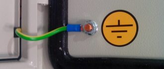
Sign and color marking of AP elements
In accordance with the requirements of GOST R 50462, conductors and buses of electrical networks with a grounded neutral must be marked “PE” with the addition of a dashed line of alternating yellow and green stripes at the end sections of the route. At the same time, the tires of the working “zero” are indicated in blue and marked as “N”.
In those circuits where neutral working conductors are used as a protective grounding element with a connection to a grounding device, blue color is used when designating them.
At the same time, they are labeled “PEN” and alternating yellow and green strokes are added to the end sections of the schematic symbols.
It should be noted that strict compliance with all provisions and requirements of GOST and PUE will allow the consumer to organize the safe operation of the equipment at his disposal.
Protection by grounding and zeroing
To ensure the electrical safety of people, a combined method of grounding and neutralizing electrical equipment is often used. Grounding is ensured by connecting the protective housings to the neutral of the supply power line. This allows you to convert the mains voltage that reaches the installation body into a single-phase short circuit. Both grounding and grounding perform a protective function, but in different ways.
When grounding, an additional device is used to reduce excess potential. To operate the grounding system, it is enough to connect the electrical installation housing to the neutral of the supply network.
When working in potentially hazardous areas, the use of one of the described methods is mandatory. Responsible employees must clearly understand the difference between one method of protection and another and know what the ground loop should be for each type of equipment.