When designing, installing and operating electrical installations, industrial and household electrical equipment, as well as electrical lighting networks, one of the fundamental factors in ensuring their functionality and electrical safety is precisely designed and correctly executed grounding. The basic requirements for grounding systems are contained in paragraph 1.7 of the Electrical Installation Rules (PUE). Depending on how and with which grounding structures, devices or objects the corresponding wires, devices, device housings, equipment or certain network points are connected, natural and artificial grounding are distinguished.
Natural grounding conductors are any metal objects that are constantly located in the ground: piles, pipes, fittings and other conductive products. However, due to the fact that the electrical resistance to the spreading of electric current and electric charges in the ground from such objects is difficult to control and predict, the use of natural grounding when operating electrical equipment is prohibited. The regulatory documentation provides for the use of only artificial grounding, in which all connections are made to grounding devices specially created for this purpose.
The main standardized indicator characterizing how well the grounding is performed is its resistance. Here the resistance to the spreading of current entering the ground through this device - the ground electrode - is controlled. The magnitude of grounding resistance depends on the type and condition of the soil, as well as the design features and materials from which the grounding device is made. The determining factor influencing the value of the resistance of the ground electrode is the area of direct contact with the ground of its constituent plates, pins, pipes and other electrodes.
About grounding in simple words
The very concept of “grounding” comes from the word “earth”, that is, soil or soil, the purpose of which is to serve as a drain for dangerous currents flowing through a specially organized circuit. For its formation, an inextricable connection of all parts of the protective system is necessary, which starts from the point of contact of the body of the grounding element and ends with the element of the grounding device (GD) immersed in the ground.
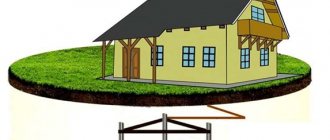
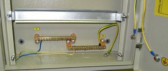
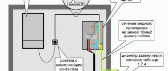
External ground loop of a private house (left). Indoor grounding (right), grounding conductor indicated by dotted line.
According to the definitions given in the technical documentation, grounding is a deliberate electrical connection of the metal housings of units with a special grounding circuit. Based on the facts considered, we can conclude that grounding is the intentional electrical contact of the protected equipment with the ground.
References
- GOST 30331.1-2013
- Kharechko Yu.V. Brief terminological dictionary for low-voltage electrical installations. Part 1// Supplement to the journal “Library of a Labor Safety Engineer”. – 2011. – No. 3. – 160 p.
- GOST R 50571.5.54-2013
- Due to the fact that GOST R 50571.5.54-2013 contains many serious errors, the article was brought into line with the work of Yu.V. Kharechko journal "Energy efficiency, energy safety, energy supervision", 2015, No. 2 - "Analysis of errors in the new GOST R 50571.5.54-2013, which applies to grounding devices and protective conductors."
- GOST 33542-2015
Grounding Requirements
After you have figured out what is the definition of the very concept of grounding, you can move on to those categories and norms that are introduced by current standards. According to the PUE, the grounding device is primarily subject to the following requirements:
- the purpose of the charger is to effectively drain dangerous currents into the ground, for which purpose their design includes a whole set of conductors and metal rods;
- All parts of the electrical installation, including metal switchboard doors, must be grounded;
- the total contact resistance of the contacts in the grounding system should not exceed 4-30 Ohms;
- when installing it in distributed loads, it is necessary to use a potential equalization system (its purpose is to eliminate uneven voltage distribution).
Additional information: Since the main purpose of grounding is to ensure the safety of personnel working with the equipment, during its operation special attention is paid to the reliability of operation.
The quality of its work is ensured by a whole range of preventive measures and periodically organized tests.
Why does a person get electrocuted?
In order to answer the question posed, you will need to familiarize yourself with the malfunctions that periodically occur in existing electrical equipment. The fact is that during its long-term operation, the insulation may be destroyed and the exposed power supply wire may come into contact with the body of the electrical installation.
If the equipment being operated does not have grounding, this threatens the operator working with it with an electric shock (photo on the left). A similar effect occurs when a person’s body accidentally comes into contact with conductive parts of a washing machine or bathtub, for example.
Grounding principle
After familiarizing yourself with the definition of grounding systems and the requirements for them, you should understand what grounding is and what it is intended for. To do this, first of all, you should know that a person’s feet through a reinforced concrete floor always have some contact with the ground.
When a person touches the body of equipment exposed to high potential, current flows through his body and legs into the ground, that is, he is a link in this chain.
Please note: Even small currents are dangerous to humans, and when they reach a value of 100 mA, death is possible.
In order to understand how the grounding system works, it should be taken into account that the housing of electrical equipment is connected to the ground (grounded) through a set of conductors and metal pins. Through this intentional connection, the human critical potential is reduced to a safe level. In this case, emergency currents “flow” through the grounded body to the ground, bypassing the human body.
What does the design of the grounding device consist of?
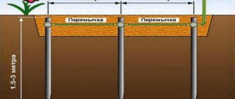
First you should get acquainted with the elements that make up its design. A typical grounding loop is a structure of three steel grounding rods driven into the ground at the corners of a trench dug to a depth of approximately 0.7-0.8 meters. Grounding conductors can be steel angles or copper-plated rods.
The length of the part of the grounding conductors immersed in the soil must be at least 2.5 meters. The exact values of these parameters are selected taking into account the nature of the soil at the location where the circuit is being constructed and the climatic conditions in the area. You can learn more about the grounding loop and its installation in our article “Grounding loop, what it is and how it works.”
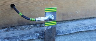
Parts of steel blanks protruding from the ground by 10-15 cm are welded together with metal plates 40 mm wide (at least 4 mm thick). In the upper part of one of the vertical electrodes, a contact zone is arranged in the form of a threaded bolt welded onto it. The end of a copper bus coming from the body of the grounded device is attached to it using a nut, the cross-section of which should not be less than 6 sq. mm.
Additional information: To reduce the resistance of the emergency current flow circuit, this connection is sometimes welded.
External ground loop
Upon completion of the main work, the trench with the structure placed in it is filled with previously discarded earth, from which stones and unnecessary debris are removed.
According to the requirements of the PUE, any grounding system must comply with technical standards in terms of the maximum permissible leakage current resistance. Its value should be:
- less than 8 Ohms in industrial networks with phase voltage 220/127 Volts;
- less than 4 Ohms for linear voltages 380 Volts;
- no more than 30 Ohms in household networks (this indicator is considered the maximum permissible).
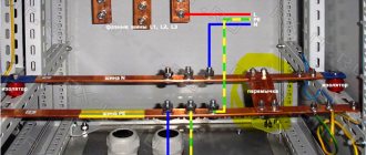
The copper core laid from the structure of the charger is fixed at its second end on a special strip mounted on the distribution panel of the facility (at home, in particular). It is called the main grounding bus (GGB), and it is intended for assembling all protective conductors in one place. Copper conductors diverge from it directly to consumers (through sockets to device housings).
How to calculate the parameters of the main grounding elements
Based on the results of such calculations, a drawing of the grounding device of the facility is designed.
Important! The device, mounted in accordance with all the calculated data of the grounding scheme, allows you to achieve maximum operational efficiency of the entire protective grounding complex.
The basis of the calculations is the permissible limits of step and touch voltage. Based on them, the configuration (size, number) of grounding conductors and the principle of their placement are calculated.
Calculations are performed based on the following data:
- Description of the characteristics of specific electrical equipment: installation type; main structural elements of the device; operating voltage; Possible options that allow grounding of neutrals of both transforming and generating devices.
- Grounding configuration. Such data is necessary to determine the optimal immersion depth of the electrodes.
- Information about studies conducted to measure soil resistivity in a specific area. Additionally, the climatic information of the zone in which the system is being installed is taken into account.
- Information on suitable natural earthing elements that can be used in your work. Data are needed on the real values of current spreading in these objects. They can be obtained by special measurements.
- The result of a standard calculation of the exact indicators of the estimated current short circuit on the soil.
- Calculated values of regulatory standardization of permissible voltage characteristics according to PUE.
- Indicators of resistance to seasonal freezing of the soil layer during the period of drying and freezing. Taking into account such values is necessary for calculating grounding elements that are located in a homogeneous environment. Special standardized coefficients are applied.
- If it is necessary to install a complex group of grounding conductors, consisting of several elements, it is necessary to know all the potentials that will be induced on the mounted electrodes. To do this, we need data on the resistance values of all soil layers.
Important! If the system is placed in two layers of soil, the resistance value of each of them is taken into account. This is necessary to determine accurate data on the power parameters of the top soil layer.
Natural and artificial grounding
Natural grounding is an object or structure that has reliable contact with the ground due to the functions it performs. This category includes:
- water and heating pipes laid directly in the ground;
- any metal structures and their elements that have good contact with the soil;
- sheaths of welding and similar cables;
- metal mortgages and tongues, etc.
Worth noticing! In this case, special efforts will not be required to arrange functional grounding, since the elements of the natural grounding system are already ready for connecting grounding conductors.
Natural grounding systems
In a situation where such systems cannot be found, you have to install homemade chargers.
Artificial grounding is considered to be a deliberately organized electrical contact of two bodies, one of which is the protected device, and the second is the so-called “grounding loop”. This component is a special distributed (sometimes point) structure based on metal rods placed deep in the ground.
As a rule, steel rods with a diameter of up to 12 mm and a length of at least 2.5 meters are used as vertically driven electrodes. To arrange horizontal jumpers that ensure electrical contact between two bodies, metal corners 50x50x6 mm and 2.5-3 meters long are taken (they can be replaced with pipes with a diameter of about 6 mm or more).
Isolated Neutral Systems
During the transmission and distribution of electric current to consumers, a three-phase system is used. This makes it possible to ensure symmetry and uniform distribution of current load.
Such a device creates a mode that involves the use of a transformer booth and generators. Their neutral points are not equipped with a ground loop.
The isolated type of neutral is used in the power circuit when connecting the secondary windings of transformer installations in a delta diagram and in the absence of power during emergency situations. Such a network is a replacement circuit.
The insulated neutral contributes to the penetration of the insulating coating during a short circuit and the occurrence of a short circuit in other phases.