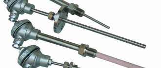
Each radio component in the electrical circuit has its own purpose. Some change parameters, others are status indicators or command executors.
There are radioelements responsible for safety and protection (we are not talking about banal fuses). For example, a varistor, which sharply changes its characteristics during voltage surges.
This property is used in protection systems for power supplies and switching devices. In addition, it is used as a simple pulse voltage filter. The part is inexpensive, but quite effective.
If your extension cord or electrical appliance does not perform its function after a power surge, do not rush into delving into the circuit design. Sometimes it is enough to know how to test a varistor with a multimeter.
What is this element and how does it work?
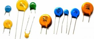
Varistors are a type of resistors made of semiconductor.
Designation on the diagram
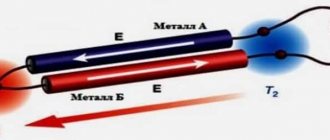
The peculiarity of this element is an abrupt change in resistance at certain voltage values. That is, up to a given value, the resistance of the varistor is kept in a stable state. After exceeding the voltage, the resistance rapidly decreases and tends to zero.
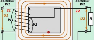
As can be seen in the volt-ampere characteristic graph, the current flowing through the varistor is stable over a given voltage range. As it increases, the current increases sharply. This happens precisely because of the avalanche-like decrease in resistance.
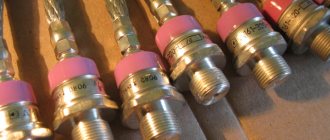
To know how to check a varistor for serviceability with a multimeter, consider its design.
The ceramic layer contains zinc oxide crystals. Depending on their concentration, when a certain voltage is reached at the connecting terminals, the resistance of the ceramic layer and the current flowing through it change.
How a viristor works, a clear example - video
Of course, there is a so-called survivability threshold: the magnitude of the current multiplied by the transit time. When a critical value is reached, the part is thermally destroyed and the circuit will be open . The performance of the varistor depends on this value: that is, the ability to withstand voltage surges.
For example, varistor K275: It can operate in circuits up to 450 volts, and is triggered when the voltage reaches 275 volts. The ability to absorb energy of 151 J allows it to take on a current of 8000 amperes within a few milliseconds. Then the part fails.
Application of devices
Varistors are used to protect electronic devices from surge voltages whose amplitude exceeds the rated power supply. Thanks to the use of a semiconductor resistor in power supplies, it becomes possible to avoid many breakdowns that can damage the electronics. Varistors are also widely used in ballast circuits, which are used in lighting elements.
Some voltage and current stabilizers also use specialized semiconductor resistors, and varistor-dischargers with voltages of more than 20 kV are used to stabilize power in power lines. It can also be connected to the wiring diagram (diagram 1), protecting it from overloads and unacceptable amplitude values of current and voltage. When the wiring is overloaded, it heats up, which can lead to a fire.
You might be interested in Wago Terminal Blocks for Electrical Connections
Scheme 1 - Connecting a varistor for a 220V network.
Low-voltage varistors operate in a voltage range from 3 V to 200 V with a current from 0.1 to 1 A. They are used in various equipment and are installed mainly at the input or output of the power source. Their response time is less than 25 ns, however, this value is not enough for some devices and in this case additional protection circuits are used.
However, the technology for their manufacture does not stand still, since it has created a radio element with a response time of less than 0.5 ns. This semiconductor resistor is made using SMD technology. Disc-type designs have a higher response time. Multilayer varistors (CN) are reliable protection against static electricity, which can damage various electronics. An example use is the production of mobile phones that are susceptible to static discharge. This type of varistors are also widely used in the field of computer technology, as well as in highly sensitive equipment.
The use of varistors in protection circuits
Based on the properties of the element, it is logical to use it in bypass circuits of the main electrical circuit. When the supply voltage increases, the varistor will act as a kind of shunt.
During a pulsed (several milliseconds) voltage surge, the main current will bypass the circuit. When the parameters are restored, the power supply to the circuit will instantly resume.
However, there is a risk of a prolonged increase in voltage; the protection will not work. Therefore, a disconnecting device is installed in the power circuit with a varistor: a fuse or a circuit breaker.
The simplest example is that a varistor is connected parallel to the power supply in an extension cord with protection. When there is a voltage surge, the element actually forms a short circuit and the circuit breaker is triggered.
Most often, varistors of the TVR 14561 type are used in such circuits.
Read also: Drilling machine 2a112 technical characteristics
Example of protection implementation
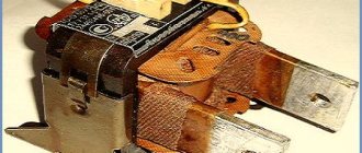
Figure 4 shows a fragment of a computer power supply circuit diagram, which clearly shows a typical varistor connection (highlighted in red).
Figure 4. Varistor in the ATX power supply
Judging by the figure, the circuit uses the TVR 10471K element, we use it as an example of decoding the markings:
- the first three letters indicate the type, in our case this is the TVR series;
- the next two digits indicate the diameter of the case in millimeters, respectively, our part has a diameter of 10 mm;
- Then there are three numbers that indicate the effective voltage for this element. It is deciphered as follows: XXY = XX*10 y, in our case it is 47*10 1, that is, 470 volts;
- the last letter indicates the accuracy class, “K” corresponds to 10%.
You can also find simpler markings, for example, K275, in this case K is the accuracy class (10%), the next three digits indicate the magnitude of the effective voltage, that is, 275 volts.
How to check the performance of a varistor?
We already know that a varistor is essentially a resistance. Therefore, it can be checked with a tester. The simplest way is to measure resistance. It is necessary to remove the part from the circuit and check the resistance in different measurement ranges.
The resistance should be infinitely high - this indicates the serviceability of the varistor. If the circuit does not have additional resistance in the connection circuit, you can check the varistor with a multimeter without desoldering.
For example, in the same extension cord. Just remember to unplug the plug from the socket and turn off all consumers connected to the extension cord.
If it is necessary to accurately measure parameters, it is necessary to assemble a circuit from a not too demanding consumer (for example, a powerful incandescent lamp) and a fuse.
By load we mean the same lamp.
Functional check
When devices malfunction, the state of the power circuits is first determined, and the task arises of how to check the varistor. First, an external examination is done.
Check for carbon deposits, blackening or mechanical damage. If any of this is present, the varistor needs to be replaced. Otherwise, unsolder at least one pin.
Without soldering the contacts, it will not be possible to measure the resistance of the varistor, since it is connected in parallel to the entire circuit of the device or some of its modules. Therefore, instead of determining the resistance of the varistor, at best, the total resistance of the entire device will be measured.
To desolder the lead, you need a soldering iron, desoldering pump, and pliers. The area around the terminal is heated with a soldering iron. The molten solder is pumped out using a desoldering pump. Use pliers to remove the varistor lead from the board.
Then a direct test of the varistor begins with a multimeter or ohmmeter. The operating mode switch is set to the “resistance measurement” position. The largest measurement scale (200 MΩ) is selected.
The probes are connected to the varistor terminals. Resistance is measured. Then the probes are swapped and the second value of the measured resistance is recorded.
The multimeter should show values in the tens of megohms. If in at least one measurement the multimeter shows values other than MOhm, it means that the varistor is faulty and needs to be replaced.
Some devices have a fuse in series with the varistor. Then just take it out and we get a version with one free contact. There is no need to solder anything.
Next, you should use a multimeter, and how the varistor is checked and measurements are taken was described above.
How to check S14 K275 using this method?
We know that the trigger voltage is 275 volts. When a voltage of 220 volts is supplied, the circuit operates in operating mode: the varistor has infinite resistance, current flows through the main circuit, and the lamp lights up.
We apply increased voltage to the input (for example, 400 volts). The varistor goes into protection mode (the resistance drops sharply, current flows through it), the fuse blows, and the lamp goes out. Conclusion: the varistor is working.
Multimeter testing methods
To check a varistor, as well as any other radio element, the easiest way is to use devices specially designed for this. Multimeters are used as such devices. The main parameter that can be measured is the internal resistance of the element. But before you directly start checking the varistor, you should prepare.
In addition to the multimeter, you will need:
Measuring the resistance of an element can be carried out without unsoldering it from the circuit, but to obtain reliable data, at least one of its pins should be disconnected from the board. All preparation boils down to the fact that the semiconductor element is first visually inspected for the absence of: splits, blackening, cracks. If a burst housing is immediately visible, then no further inspection can be carried out. Such a varistor is clearly faulty.
A soldering iron, flux and solder will be needed to unsolder one of the terminals of the element or even remove it entirely, and after checking, solder it back if necessary. The datasheet for an element is an official document issued by the manufacturer. It indicates all the basic data and characteristics.
The datasheet is used to know exactly what the operating resistance of a radio component is at rest. If, when measured with a multimeter, the resistance of the varistor does not differ by more than 10%, then it is considered to be in good condition. If the resistance is significantly less than that indicated in the datasheet, then it will need to be replaced. It is important to note that in normal conditions the resistance of a varistor reaches several hundred megaohms, so the tester must be able to measure within this limit.
Measurements with a dial gauge
Such a device is considered analog. Its design uses an electromechanical head. It is a frame placed in a magnetic field. Depending on the current strength, the arrow in the frame deviates, stopping in a certain position. The range of needle deflection is graduated by numbers, according to which the resistance is calculated.
Before you start checking the varistor, you will need to set up the dial multimeter. To do this, it is calibrated. Its essence comes down to setting the zero position of the arrow by rotating a special handle while connecting the probes to each other.
To do this, the switch button selects the operating mode corresponding to the “Ω” icon, and the slide switch is set to the highest limit of resistance measurement by the tester. Most often it is designated as “x100”, which corresponds to megaohms. The resistance is measured from the power source (battery) installed in the device. Therefore, if you cannot set the needle to zero, the battery will need to be replaced.
When carrying out direct measurements, touch one terminal of the varistor with one probe of the tester, and touch the other with the other. As a result, three outcomes are possible:
- The arrow will deflect to zero or show resistance in the kilo-ohm region. A conclusion is made that the element is faulty (breakdown).
- The measurement result is within hundreds of megaohms. This reading indicates the serviceability of the varistor.
- When you touch the terminals of the radio element, the arrow does not react in any way. Possible reasons are as follows: the operating range of the device is not enough to measure the resistance value of the varistor, the device is faulty, the radio element is faulty (break).
Digital tester
Using a digital multimeter, checking the varistor for functionality will be a little easier than using an analog one. This is due to the fact that the digital tester has an LCD display in its design, which clearly displays the measured resistance.
The operation of this type of tester is based on an analog-to-digital converter, the operating principle of which is based on comparing the measured signal with a reference one. It should be noted that if, when you turn on the tester, a flashing battery icon appears on the screen, the battery will need to be replaced. The procedure for measuring the resistance of a varistor can be represented as follows:
The switch sets the maximum resistance measurement limit. Typically this limit is indicated by a number and a letter. If just numbers are written, then the unit of measurement is Ohm, the letter K after the number means kilo-ohm, the letter M means mega-ohm.
- The probes are fixed on two terminals of the varistor, and the reverse ends of the wires with plugs are inserted into the tester sockets marked Ω and COM. Since the polarity of the signal applied to the varistor does not matter, it does not matter which wire is connected to which terminal of the element. Although it is customary that a black cord is inserted into the COM connector.
- The device is turned on by pressing the ON/OFF button on the tester.
- If a unit is displayed on the indicator, this means that a small measurement limit has been selected.
- If numbers other than one are displayed on the screen, then this is the value of the measured resistance.
When interpreting the measurement result, the tolerance should also be taken into account. Each radio element has its own tolerance indicator. For example, if the tolerance is 10 percent and the internal resistance of the varistor is specified as 100 MΩ, then the results obtained should be between 90 and 110 MΩ. If the measured resistance of an element is found to be below or above this range, then it can be considered faulty.
How to check the varistor on the board?
If the part is part of a complex electrical circuit, it will be impossible to accurately determine the resistance parameters. In parallel with the varistor there are a lot of resistances that will distort the readings of the device.
However, this method is so complicated (in terms of calculations) that radio amateurs never practice it. If you do not want to damage the integrity of the circuit board, it is enough to unsolder at least one varistor leg.
Then you connect the multimeter to the part and perform the test in the standard way. To be fair, we note that a burnt varistor is almost always destroyed or has traces of charring.
This part is not classified as expensive: the cost of a simple varistor is in the range of 7r – 50r. So, if there is a suspicion of a malfunction, you can simply replace the element.
How to replace a varistor on a board or select an analogue - video
How can I replace the JNR 7D241K varistor from a computer power supply?
Help with color music device Illusion
I'm not very good with computers
Help with protection from u 101
- Comments 7
- Pingbacks 0
what is the problem, any 240V varistor of suitable size
Read also: Treatment of eyes after welding at home
Is it possible without it at all?
Nikita, it’s not advisable, it gives a smooth start.
Ghost, it dampens the current pulse, and when the block starts, the PWM itself makes a smooth start
Nikita, for the general development, a varistor has nothing to do with “it dampens a current pulse” or a voltage pulse, maybe it can only create a current pulse.
Zhenya, I meant that when the voltage exceeds the limit for the varistor, it will begin to pass current through itself and thereby dampen the high-voltage pulse
Ghost Roman, a smooth start is ensured by the PWM controller itself and the thermistor connected in series with the load (like a charging capacitive divider for a half-bridge in an SMPS). A varistor is a means of protection against long-term supply overvoltages (if a lightning discharge blows in, even a fuse does not save, everything burns out with static and huge impulses)
If, when repairing an air conditioner, you find a blown fuse on the circuit board, do not rush to change it immediately; first find out the reason why it burned out.
Most likely this happened due to power surges in the network.
When measuring the supply voltage in the network, it constantly fluctuates, and not always within safe limits for air conditioners.
Plus, the network always contains short pulses with voltages of several kilovolts. This happens due to the constant switching off and on of inductive and capacitive loads (electric motors, transformers, etc.), as well as due to atmospheric electricity.
Air conditioners, like any other electronic equipment, are protected in this case by varistors. More precisely, the electronic filling of the air conditioner - the control board.
Advantages and disadvantages
To use a varistor, you should become familiar with its positive and negative sides, since the protection of electronics depends on this. The positive qualities include the following:
- High response time.
- Tracking differences using the inertia-free method.
- Wide voltage range: from 12 V to 1.8 kV.
- Long service life.
- Low cost.
A varistor, in addition to its advantages, has serious disadvantages that should be taken into account when developing any device . These include:
- Large capacity.
- Do not dissipate power at maximum voltage.
The capacitance of a semiconductor device ranges from 70 to 3200 pF and therefore significantly affects the performance of the circuit. This value depends on the design and type of device, as well as on the voltage. However, in some cases this disadvantage is an advantage when using it in filters. The value of the larger capacitance limits the voltage value.
At maximum voltage values, varistors-dischargers should be used to dissipate power, since an ordinary semiconductor device will overheat and fail. Every radio amateur should know the algorithm for checking a varistor, since when contacting service centers there is a possibility of paying more for repairs than it actually costs.
Operating principle of a varistor
Essentially, a varistor is a nonlinear semiconductor resistor, the conductivity of which depends on the voltage applied to it. At normal voltage, the varistor passes a negligibly small current through itself, and at a certain threshold voltage it opens and passes the entire current through itself. Thus, it filters short pulses; if the pulse is longer, and the current flowing through the varistor exceeds the rated current of the fuse, it will simply burn out, de-energizing and protecting the load.
Purpose and characteristics
A varistor is an electronic device that has two contacts and has a nonlinear-symmetric current-voltage characteristic. The term “varistor” comes from the Latin words variable - “changeable” and resisto - “resistor”. At its core, it is a semiconductor resistor that can change its resistance depending on the voltage applied to its terminals.
This type of resistor is made by sintering a semiconductor and a binder material at high temperatures. Silicon carbide, which is in a powdered state, or zinc oxide is used as a semiconductor, and glass, varnish, and resin are used as a binder. The element obtained after sintering is subjected to metallization with further formation of leads. By their design, the devices are made in a form similar to a disk, tablet, cylinder, or film type.
Having the property of sharply reducing its resistance when a certain voltage appears at its terminals, a varistor is used in electronic circuits as a protective element. When a voltage surge of a certain magnitude occurs, the semiconductor device instantly reduces its internal resistance to tens of ohms, thereby practically short-circuiting the circuit, preventing the impulse from damaging the remaining elements of the circuit. Therefore, an important parameter of a varistor is the voltage value at which breakdown of the device occurs.
Varistor marking
There are a huge number of varistors from different manufacturers, with different threshold operating voltages and designed for different currents. You can find out which varistor was installed by its marking. For example, marking varistors CNR :
CNR-07D390K , where:
- CNR-series, full name CeNtRa metal oxide varistors
- 07- diameter 7mm
- D – disk
- 390 – actuation voltage, calculated by multiplying the first two digits by 10 to the power equal to the third digit, that is, 39 multiplied by 10 to the zero power, you get 39 V, 271-270 V, etc.
- K – tolerance 10%, that is, the voltage spread can fluctuate from the nominal by 10% in any direction.
Read also: How to measure an angle less than 90 with a protractor
General information
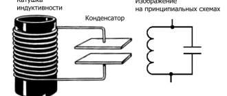
A varistor is a semiconductor resistor that decreases its resistance as the voltage increases. The conventional graphic symbol (UGO) is presented in Figure 1, which shows the dependence of the resistance of the radio component on the voltage value. In the diagrams it is denoted znr. If there is more than one, then it is designated in the following form: znr1, znr2, etc.
Many beginning radio amateurs confuse a variable resistor and a varistor. The operating principle, main characteristics and parameters of this element differ from a variable resistor. In addition, a common mistake in drawing up electrical circuit diagrams is the incorrect UGO. A varistor looks like a capacitor and is recognized only by its markings.
Expert opinion
It-Technology, Electrical power and electronics specialist
Ask questions to the “Specialist for modernization of energy generation systems”
Varistor. What it is? Operating principle: high capacitance depends on the voltage and type of element, ranges from 70 to 3200 pF and affects the performance of the device; Ask, I'm in touch!
How to find a varistor on the board?
According to the diagram above, it is clear that this element is located next to the fuse at the point where the power wires enter the board. This is usually a yellow or dark green disc.
In the photo the varistor is indicated by a red arrow. One might think that the varistor is a blue part covered with black soot, but on magnification you can see cracks on the varistor body, from which the parts located nearby are covered with soot. This can be clearly seen from the reverse side, where the symbols are written. Even if they are not there, you can recognize a varistor, knowing that it is connected in parallel to the load or by the markings on its body.
VA1 is a varistor , and the blue part next to it is capacitor C70.
Do not confuse them, they are the same in shape, so be guided by the markings and symbols on the board.
After you have found a varistor, you need to unsolder it so that a new one can be installed in its place. To solder varistors, I usually use a gas soldering iron, because there is not always power supply at the repair site - at a facility under construction, on a roof, for example. It is also very convenient use a desoldering pump - warm up the soldering area and remove the melted solder with a desoldering pump.
But for these purposes, tweezers or ordinary pliers are quite suitable - you need to grab the leg of the part and pull it out when the solder melts. If your solder does not melt well, then most likely it is high-temperature on the board - the so-called lead-free (you may have noticed on my board the inscription PbF - plumbum free ). In this case, you need to either increase the temperature of the soldering iron tip or drop another lower temperature one on top, the soldering area will melt and the part can be removed. After this, we insert a new varistor and solder it.
For soldering, it is very convenient to use solder in the form of a wire that already has flux inside.
Also note that most boards are double-sided, so you need to solder the legs of the part on both sides of the board, since it often happens that the leg of the part acts as a jumper between tracks on different sides of the board.
After replacing the varistor, all that remains is to install a new fuse and install the board in place.
Typically, air conditioner circuit boards contain varistors for a voltage of 470 V, and fuses rated from 0.5 A to 5 A. Therefore, I recommend that you always have a small supply of these parts with you.
For those who want to see the process more clearly, I am posting a video tutorial:
For those who need to repair the board by replacing the varistor, our service specialists will help, see prices here.
Disassembling the power supply and troubleshooting
The repair began with disassembly and checking the fuse. When checking, the multimeter showed infinity, which indicates a broken fuse.
Power supply after disassembly. Location of the fuse on the board.
Checking the fuse
Often, a blown fuse is only a consequence, and the cause of the breakdown has yet to be found. For these purposes, I used a 100W incandescent lamp, replacing it with a fuse. In normal condition, it should light up (at the moment of charging the network capacitors), and then go out. In standby mode, when the power supply consumption is low, the lamp may light up a little and then go out. This behavior will be repeated cyclically.
If the lamp lights up brightly, this may indicate that there is a short circuit in the primary circuit, or there is an excessive load at the outputs of the power supply.
Having thrown the lamp, it lit up brightly.
The incandescent lamp lights up brightly when connected.
To check whether the power supply produces any voltage, I again connected the tester to its output. As a result, it showed the presence of output voltages.
Output voltages from the power supply
This was a good sign; all that remained was to determine the cause of the increased current consumption. At first, I thought about a diode bridge, but at the very beginning of the circuit, after looking a little closer, I saw a burnt varistor. Its malfunction was difficult to notice, since it was covered with a thermal insulating tube, after removing which everything fell into place. The varistor was burnt out and clearly out of order.
Varistor after desoldering from the board
After removing the thermal insulation tube everything fell into place
Voltage drop across the varistor. Ideally, the tester should not show anything.
Marking and main parameters
The marking of varistors is different, since each manufacturer of these radio components has the right to install it independently. This is primarily due to its technical characteristics. For example, differences in voltages and required current levels for its operation.
Among domestic ones, the most common is K275, and among imported ones - 7n471k, 14d471k, kl472m and ac472m. The most popular is a varistor, the marking of which is CNR (there are also hel, vdr, jvr). In addition, the alphanumeric index 14d471k is attached to it, and this type of designation is deciphered as follows:
- CNR - metal oxide type.
- 14 - device diameter equal to 14 mm.
- D is a disc-shaped radio component.
- 471 is the maximum voltage value for which it is designed.
- K is the permissible deviation of the classification voltage equal to 10%.
There are technical specifications required for application in the circuit. This is because different types of semiconductor resistance must be used to protect different circuit elements.
Their main characteristics:
- Classification voltage is the value of the potential difference, taken into account that a current of 1 mA flows through the varistor.
- The maximum value of the alternating voltage is the rms value at which it opens and, therefore, the value of its resistance decreases.
- The constant maximum voltage value at which the varistor opens in a DC circuit. As a rule, it is greater than the previous parameter for a current of variable amplitude.
- The permissible voltage (limitation voltage) is the value above which the element fails. Indicated for a specific current value.
- The maximum energy absorbed is measured in J (joules). This characteristic shows the amount of pulse energy that a varistor can dissipate and not fail.
- Response time (unit - nanoseconds, ns) - the value required to transition from one state to another, that is, a change in resistance value from a high value to a low value.
- Classification voltage error is a deviation from its nominal value in both directions, which is indicated in % (for imported models: K = 10%, L = 15%, M = 20% and P = 25%).
After describing the operating principle, marking features and main characteristics, the scope of application of varistors should be considered.
Capacitance values
Because the main conducting region of a varistor between its two terminals behaves like a dielectric, below its clamping voltage the varistor acts like a capacitor rather than a resistor. Each semiconductor varistor has a capacitance value that is directly proportional to its area and inversely proportional to its thickness.
When used in DC circuits, the capacitance of a varistor remains more or less constant provided that the applied voltage does not increase above the clamp voltage level and drops sharply near its maximum DC voltage rating.
However, in AC circuits, this capacitance can affect the resistance of the device body in the non-conductive leakage region of its IV characteristics. Since they are usually connected in parallel with an electrical device for surge protection, the leakage resistance of varistors drops rapidly with increasing frequency.
This relationship is approximately linear with frequency, and the resulting parallel resistance, its AC reactance Xc , can be calculated using the usual 1/(2πƒC) , as for a normal capacitor. Then, as the frequency increases, the leakage current also increases.
But along with silicon semiconductor varistors, metal oxide varistors have been developed to overcome some of the limitations associated with their silicon carbide cousins.