Purpose: protection of electrical objects from emergency currents occurring inside the controlled area with an absolute degree of selectivity without time delay.
Operating principle of differential protection
The measuring complex is operated by a differential organ consisting of current transformers and relays that constantly monitor the direction of currents in various areas and are triggered when they change.
In the nominal operating mode, the load current flows from the generator end to the consumers and has one direction along the entire line. It is monitored and taken into account by measuring relays. If a short circuit occurs in the controlled area, currents begin to feed it from all sides. At the end of the consumer line, the current reverses direction.
This is taken into account by the differential element: it is triggered and triggers the logical shutdown protection circuit. Differential protections work on two different principles:
It is used for power lines. Measuring current transformers and relays are installed at the ends of the line at different substations. Current circuits are connected by long cable lines.
For longitudinal differential protection, the measuring current relay is connected so that the current vectors coming from the measuring transformers are applied counter to the winding. In this case, during the nominal operating mode or the occurrence of an external short circuit outside the controlled zone, the current vectors will be mutually compensated and destroyed on the winding. There will be no reason to trigger it.
When a short circuit occurs inside the line, currents begin to flow through the winding of the current relay. It works.
More promising high-frequency differential protection (DFZ, BCHB, etc.) use the same principle, but communication between the ends of the lines to compare the directions of currents on them is carried out through communication channels due to the transmission of high-frequency pulses.
It is created for objects located at the same substation, for example, power transformers, motor blocks, generators, etc.
Measuring current transformers operate at the same substation, but at different connections of the protected object. The current relay winding is also connected counter to the direction of the line current vectors. Otherwise, the transverse differential protection repeats the operating principle of the longitudinal one.
The various types of differential protection are discussed in more detail here:
If you liked this article, share a link to it on social networks. This will greatly help the development of our site!
Subscribe to our channel on Telegram!
Just follow the link and connect to the channel.
Don't miss updates, subscribe to our social networks:
Source
Transverse differential protection
Longitudinal diff. generator protection does not operate in case of turn faults in the stator winding, since the currents passing from the main and neutral terminals are the same in this case.
Protection against turn faults is not provided for generators that do not have parallel branches in the stator winding due to the lack of simple methods for its implementation.
On powerful generators that have two or more parallel branches in the phases of the stator winding, special transverse differential protection , designed to protect the generator from turn faults in the stator winding. In this case, on the side of the zero terminals, each parallel branch must have an isolated output.
The operating principle of the transverse differential. protection is based on comparison of the geometric sum of currents in parallel phase branches of the generator stator winding.
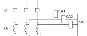
Such a comparison can be made using a three-system or single-system lateral protection scheme. Typically, a single-system circuit is used, which is performed using one current transformer installed in the circuit between two zero points of the parallel branches of the stator winding connected in a star and one relay comparing the sum of the currents of the parallel branches of all three phases of the stator winding of the generator.
A simplified diagram of a single-system transverse differential generator protection is shown in Fig. 7-5.
In normal mode and with external short circuit. the geometric sum of the currents of each group of parallel phase branches connected in a star is equal to zero and only the unbalance current enters the protection relay.
Operating principle
The main function of differential protection is to prevent phase-to-phase and short circuits in electrical equipment and systems with a solidly grounded neutral. It is considered a type of relay protection and works by comparing current values and current directions on the sides of an object.
The operation of differential protection is based on the comparison of phase currents that flow through the protected section of the network or pass through the protected equipment. The current strength is measured at the ends of the sections using two current transformers connected by secondary circuits to a current relay. As a result, the relay winding receives the difference in current from each transformer. Thus, differential protection is a tripping system based on current differences.
In normal operation, one current value is subtracted from another. The ideal result is considered to be a zero current value in the current relay winding. If a short circuit occurs in the protected area, the relay winding receives not the difference, but the sum of the currents. Under their influence, the relay contacts close, giving the command to turn off the damaged area.
Under real operating conditions, the current flowing through the relay coil will always differ from zero. This is known as unbalance current, and its presence depends on a number of factors.
- Firstly, both transformers are not identical and differ in technical characteristics. To reduce the influence of this factor, the manufacture of current transformers participating in the differential protection system occurs in pairs, with adjustment to each other at the manufacturing stage. As an additional measure, the number of turns of the measuring transformer is changed, adjusted to the transformation ratio of the protected device.
- Another reason for the appearance of an unbalance current may be the occurrence of a magnetizing current in the windings of the protected transformer. Under normal operating conditions, this current may be 5% of the nominal value. The magnetizing current in some cases is several times higher than the rated value, especially when switching the transformer from no-load to load and during other transient processes. Taking this factor into account, the operating current in the relay is set above the maximum value of the magnetizing current.
- Unbalance current sometimes occurs due to unequal connection of windings installed on the primary and secondary sides of the protected transformer device. In such cases, the current vector of the secondary circuit is shifted relative to the primary circuit current by 30 degrees. It is almost impossible to adjust and compensate for this difference by selecting the turns on the transformer. This problem is solved by connecting the windings: on the triangle side - with a star, and on the star side - with a triangle.
8.1. Purpose and types of differential protection
On lines extending from the busbars of power plants or hub substations, stability conditions often require that short-circuits be disconnected within the entire protected line without a time delay. This requirement cannot be met using instantaneous current cut-offs that protect only part of the line. In addition, cutoffs are not applicable due to the selectivity condition on short power lines, where the short-circuit currents at the beginning and end of the line are approximately the same. In these cases, differential protection (DP) is used, which provides instantaneous switching off of a short circuit at any point in the protected area and does not operate in case of a short circuit outside the coverage area.
Differential protections are divided into:
longitudinal – for protection of both single and parallel lines;
transverse - to protect only parallel lines.
Protection of generators and units
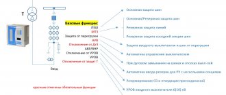
In accordance with the PUE, the following protections are installed on modern turbogenerators:
Longitudinal differential protection.
The protection is the main fast-acting protection; it operates without a time delay in case of phase-to-phase faults in the generator and at the terminals in the area between the differential protection current transformers. Provided the protection is sufficiently sensitive, it can also respond to double earth faults when one earth fault point is within the generator's differential protection range.
Transverse differential protection.
They are installed on turbogenerators that have parallel branches of the stator winding of each phase.
The protection operates without a time delay in case of turn faults in the stator winding.
Protection against ground faults in the stator winding.
To protect generators operating on busbars with voltages above 1 kV from single-phase faults in the stator winding, current protection is provided that responds to the full ground fault current or its higher harmonic components. The protection is built against transient processes and operates:
– with a capacitive ground fault current of 5 A or more – to turn off all generator switches and extinguish its field;
– with a capacitive ground fault current of less than 5 A – per signal.
On generators operating in a block with a transformer (autotransformer) with a power of more than 30 MW, protection against ground faults in the generator voltage circuit is provided, covering, as a rule, the entire stator winding. The protection area also includes the low voltage winding of the block transformer and the generator busbar voltage.
When the block generator power is 30 MW or less, protection is applied that covers at least 85% of the stator winding from the linear terminals of the generator.
The protection operates with a time delay of no more than 0.5 seconds to turn off the unit.
Negative sequence current protection.
It is mandatory for modern turbogenerators to protect against the flow of negative sequence currents. The duration of the protection is determined by the thermal characteristics of the generator. Protection, as a rule, is performed with a time delay depending on the magnitude of the negative sequence current (the greater the current
reverse sequence, the faster it should be turned off
generator). In some cases, protection is carried out in stages
actions by current and time.
Protection against external symmetrical short circuits. This protection is performed on a resistance relay. In old schemes, protection is carried out in the form of a single current relay with a voltage start. The protection operates on tripping with a time delay.
Protection against asymmetrical generator overload currents. A sensitive negative sequence protection stage is used and operates with a time delay on the signal.
Protection against symmetrical generator overload currents is performed by a separate current relay and operates with a time delay on the signal.
Overvoltage protection is designed to prevent voltage increases above 1.2 Unom. at the stator terminals of a generator operating at idle speed.
An increase in voltage may occur due to a malfunction of the excitation system. The protection is activated automatically after the generator is switched to idle and is released after the generator is switched on under load. The protection acts to dampen the generator field.
Protection against asynchronous mode (loss of excitation).
Asynchronous mode occurs when the generator remains without excitation. The protection is performed on a resistance relay and reacts to a change in the direction of reactive power when, upon loss of excitation, the generator begins to consume reactive power and continues to carry an active load.
Protection of the rotor winding from ground fault.
A short circuit at one point of the generator rotor is not a dangerous condition. However, when a second short circuit of the rotor winding to ground occurs, the rotor winding current increases, which leads to its overheating. In addition, the appearance of a double ground fault leads to a violation of the symmetry of the magnetic flux and to strong vibration. Therefore, on turbogenerators with direct cooling of the rotor winding, as a rule, protection against short-circuiting of the rotor winding at one point, type KZR-3, is installed with an effect on the signal. Upon receipt of a signal, such turbogenerators must be unloaded and turned off.
For turbogenerators with indirect cooling of the rotor winding, long-term operation with a short circuit at one point is allowed, but with the introduction of protection against ground faults at two points on the signal.
Rotor protection against current overload.
The rotor is overloaded with excitation current when the regulator or excitation booster operates. Prolonged flow of increased excitation currents can lead to overheating of the rotor winding. The most modern is protection with an integral characteristic of the RZR-1 type (the time delay depends on the value of the rotor current). The protection consists of a signaling element and an element that acts to de-excite and turn off the generator.
On most generators previously put into operation, rotor overload protection is carried out on the principle of indirect overload control, recording an increase in voltage on a potentiometer connected to the rotor winding. The protection also acts on deexcitation (de-force) and block shutdown.
On generator-transformer (autotransformer) units, in addition to the listed protections, the following are installed on the generator:
Differential protection of the unit, operating without a time delay for shutting down the unit;
Gas protection of the transformer and booster transformer with on-load tap-changer from internal damage. The protection acts on the signal and shutdown of the unit.
Zero sequence current protection against short circuits to ground in a network with a grounded neutral. Protection of action
It corresponds with the first time delay for turning off the circuit breaker on the high side of the block and with the second time delay for turning off the block.
On generator-transformer (autotransformer) units, if there is a switch between the generator and the transformer, instead of differential protection of the unit, there is differential protection of the transformer (autotransformer), which operates without a time delay for disconnecting the unit. In this case, the action of the generator protection is transferred to shutting down the generator in order to preserve the branch for its own needs.
On some generator-transformer units, backup differential protection of the unit is installed. The protection backs up the differential protection of the generator, the differential protection of the transformer and the differential protection of the high voltage busbar. The protection operates with a time delay of 0.5 seconds to turn off the unit.
Areas of use
With the help of high-speed differential protection devices of one type or another, it is possible to protect the operation of most types of electrical equipment. These may include electric motors, power lines, transformers and generators of distribution substations, etc.
Arc protection
Longitudinal differential current protection is traditionally used in fault prevention circuits of the following equipment:
- Industrial transformer products;
- Selected samples of transformers for electrical substations with an operating power of over 6.3 kVA;
- Parallel connected inductive devices with a power of over 1000 kVA.
The main area of application of transverse systems is high-voltage power transmission lines (PTLs), designed for voltages of 35-220 kV. In addition, differential protection can be used on parallel-connected power lines with inputs from two different substations.
However, the use of such protection is limited by the following factors:
- Difficulty in quickly determining the location of a short circuit;
- Impossibility of using DZL in power lines with automatic machines;
- The need to turn off one of the lines operating for a common load.
Additional Information. When the high-voltage route is powered on both sides, differential protection is located at both ends, and in the case of one-way power supply - only on the power source.
Differential machines
The same type of protective devices includes household differential circuit breakers, which combine the functions of a circuit breaker and an RCD. Typically, these devices are designed in one common housing with combined performance characteristics (see photo below in the text).
Differential automatic
According to the principle of operation, all protective devices of this class are divided into electronic and electromechanical, and according to their design, they can be built into the machine or manufactured separately. It is important for a person unenlightened in the intricacies of electrical engineering to learn to distinguish between a conventional RCD and a differential circuit breaker, since this may ultimately affect its safety.
The fact is that when an electronic RCD is connected to the supply circuit, one mandatory requirement must be met, which is the need to constantly keep this line energized. If there is no adequate power supply for any reason, the protection system will not work when a leakage current appears.
Note! This situation often occurs in the event of a break in the internal power supply circuit of the switch or damage to the zero outside the facility.
In an electromechanical type RCD, the protective operation of the device is guaranteed in any situation.
In the final part of the review of differential protection systems, it should be noted that its use helps to increase the safety and reliability of electrical equipment and power lines. The widespread introduction of modern electronic technologies into power supply systems makes it possible to take into account the operating features of the vast majority of known electrical devices. This helps to increase the speed of protection response, and also significantly increases the effectiveness of its action.
Typical longitudinal DZL[edit]
On an electromechanical base with a wired communication channel: DZL-1, DZL-2. On a microprocessor base with an optical communication channel: - domestically produced ShE2607 09x, ShE2710 591 (NPP EKRA), Sh2600 05.52x, Sh2700 05.62X (Relematika); — foreign production UR L90 (General Electric), P541-546 (Alstom), RED 670 (ABB), 7SD522 (Siemens).
Transverse differential line protection
(transverse DZL) is connected to the difference in currents of parallel lines. During an external short circuit, currents of equal magnitude and direction flow through parallel power lines, and therefore the differential current in the protection is zero. During a short circuit on one of the lines, the differential current acquires a significant value, sufficient to trigger the protection. To determine the circuit to be switched off, the power direction element is used in the protection. Transverse differential line protection is used to protect parallel lines with the same or slightly different parameters. Protection is not very widespread and again, as a rule, is not installed.
Materials
.
Fedoseev A.M., Fedoseev M.A. Relay protection of electrical power systems. Textbook for universities. – 2nd ed., revised. and additional.. – M.: Energoatomizdat, 1992. – 528 p.: ill.
Types of differential protection
The differential current protection considered here can be designed in two forms: as longitudinally acting, on the one hand, and operating according to a “transverse” connection scheme, on the other. In the first case, the protected winding of a three-phase transformer or motor is connected to the gap between the two comparing differential coils of the electrical protection device (see the figure below in the text).
Longitudinal protection scheme
Overcurrent protection
From this figure it can be seen that the coils of the three executive relays are located between the beginning and end of the windings of each of the power supply phases.
Unlike the longitudinal system, transverse protection involves parallel connection of the same coils and is based on taking into account the difference in currents flowing in them.
Necessary clarification. This example is only suitable for the case where differential protection of a transformer, three-phase motor or generator is considered.
For all other types of consumers and loads, its connection diagram will be slightly different from the original one.
The secondary coil of the executive relay is located in this circuit in the break of the neutral wires of the stator windings, that is, as shown in the figure below.
Cross protection scheme
Longitudinal differential protection has the following undeniable advantages:
- A good indicator of selectivity;
- Can be used with other types of protection;
- The system is trouble-free and has high performance.
Its disadvantages include a decrease in the efficiency of operation with a large length of controlled lines.
Protection of household networks (RCD)
Surge protection in a private home
The operation of devices with differential protection installed at inputs to administrative and residential buildings does not differ significantly from the previously discussed principle of operation for transformers and motors. They also have a sensitive element that responds to an imbalance of incoming and outgoing current and reacts when it occurs by disconnecting the consumer from the supply line.
Devices of this class, used for the purposes indicated above, are called RCDs (see figure below).
Line protection with RCD
The cause of current imbalance in domestic conditions may be the following factors:
- Touch of a person or animal to exposed current carriers (wires) or to equipment housing exposed to dangerous potential;
- Destruction of electrical wiring insulation with the risk of short circuit;
- Increased humidity in the room being served (in the bathroom, for example);
- Damage to cables of household electrical appliances resulting in leakage to ground.
Note! In cases where the ouzo system operates without any disturbances in the operation of the consumer (without load from leakage currents), it should be assumed that this device is faulty and must be repaired.
A feature of the functioning of RCD systems is their response to microscopic leakage currents (μA), detected when the slightest “suspicious” passive or capacitive connection to the ground appears. Moreover, such a system operates almost instantly, providing one hundred percent protection of a person from electric shock.
In electrical engineering, it is accepted as a rule that it is possible to provide effective differential protection using an RCD only when using a three-level circuit. This means that several devices are connected in series to the protected line, designed for three levels of leakage current values: 100-300, 30 and 10 mA, respectively.
Important! Such current protection, operating on the differential principle, can be effective even at facilities where the wiring does not include a grounding bus.
Another feature of this device is the need to periodically (at least once a month) check its performance, for which it has a special button called “Test” or “Check”. In addition to the control button, the testing circuit includes a limiting resistor through which a certain current corresponding to an emergency situation is passed during testing.