RUSSIAN JOINT STOCK COMPANY OF ENERGY AND ELECTRIFICATION "UES OF RUSSIA"
RD 153-34.0-20.525-00
Part 2
UDC 621.311
Enters into force on September 1, 2000.
DEVELOPED by Novosibirsk State Technical University, Moscow Energy Institute, Research and Production Company ELNAP, Open Joint Stock Company "Company for Setup, Improvement of Technology and Operation of Power Plants and Networks ORGRES"
PERFORMERS YU.V. Tselebrovsky, A.A. Zakharov, A.G. Tarasov, V.L. Zakharov, E.L. Katz, S.V. Nesterov (NSTU); R.K. Borisov, E.S. Kolechitsky, I.V. Zharkov, A.V. Gorshkov (MPEI - NPF ELNAP); E.F. Konovalov, V.A. Borukhman, V.V. Podolsky (JSC "UES of Russia" 05/07/2000
First Deputy Chief A.P. Bersenev
INTRODUCED FOR THE FIRST TIME
These Guidelines apply to personnel of JSC energos, intersystem electric networks (IES), MES enterprises and enterprises operating electric networks, power plants, design, construction, installation and commissioning organizations involved in the operation, design and construction of grounding devices (GD) of power facilities.
The Guidelines provide methods for monitoring and testing chargers of substations and overhead line supports, methods for checking breakdown fuses and phase-zero circuits (in installations up to 1000 V) during operation and when accepting newly constructed or reconstructed chargers, and also indicate the devices used in this case.
Purpose of calculating protective grounding
The grounding device installed on the consumer side is designed to protect not only personnel servicing electrical installations, but also ordinary users.
Important! Dangerous potential can reach metal parts of equipment while working with it completely accidentally (due to damage to wire insulation, for example).
A complete grounding calculation guarantees the formation of reliable contact of the protective device with the ground, leading to the spreading of current and a reduction in the level of dangerous voltage.
Thus, the purpose of calculating grounding devices is to create conditions that eliminate the risk of damage to living organisms by high potential by reducing it at the point of closure. In the absence of a well-designed and functional grounding conductor, any touch to the frame of damaged equipment is tantamount to direct contact with the phase conductor.
Values for vertical electrodes
Digital values of the utilization factor without taking into account the influence of the grounding conductor, for vertical grounding electrodes placed in a row and along a closed loop:
| Placement in a row | ||
| 5 | 0,7 | |
| 1 | 10 | 0,6 |
| 1 | 15 | 0,53 |
| 1 | 20 | 0,5 |
| 2 | 5 | 0,81 |
| 2 | 10 | 0,75 |
| 2 | 15 | 0,7 |
| 2 | 20 | 0,67 |
When the number of electrodes is more than 80, the utilization factor is on average 0.4 with the distances between the electrodes equal to their single and double depths.
| Closed loop placement |
Contour selection
Before calculating the circuit, you are given the opportunity to choose one of the following options for grounding devices:
- A triangular structure, the parameters of which are determined at the design stage.
- An extended linear structure mounted along the perimeter of the protected object.
- Modular pin grounding design.
Each of the above methods of assembly and subsequent installation of grounding devices requires detailed consideration.
Triangular design
This option for making a locking device is the most famous and widespread among professionals and amateurs. To arrange such a structure, you will need to prepare the following elements:
- Two-meter metal rods (reinforcing bars) in the amount of 3 pieces.
- The same number of steel jumpers designed to combine the rods into a single structure.
- A copper busbar required to connect the circuit breaker with the point of collection of conductors from the grounded equipment in the distribution cabinet (GZSh - main grounding busbar).
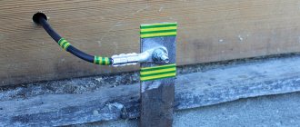
The plane of the welded contour with the pins already driven into the ground when arranging the charger should be located at a depth of approximately 30-60 cm.
Linear outline
Linear grounding is selected when it is necessary to connect several pieces of equipment located at a distance from one another to a protective structure. It consists of several pins (3) driven into the ground, the location of which relative to each other is selected from the calculated data.
Linear diagram of a ground loop for a private house
From the structure assembled according to this scheme, as in the case of a triangle, a branch (2) is made towards the distribution panel with the main shield. Before calculating such a circuit breaker, it should be taken into account that the total number of pins is limited by the mutual influence of emergency currents flowing in each single ground electrode.
Modular-pin grounding
The modular type of charger is used in situations where the area on the site in front of the house is limited in size and a single pin structure is allowed.
Installation diagram of a single grounding electrode
It contains the following elements in its kit:
- One and a half meter long steel rod with copper coating and available on
- working part threaded.
- A special coupling made of brass, providing a threaded connection of a vertically driven pin with a grounding tap.
- Brass clamps of a special design, guaranteeing reliable connection of the metal pins with the connecting strip.
- Tips for the ground rods themselves.
- An attachment with an impact platform that allows you to transmit impulse from a driving tool (vibratory hammer).
Modular-pin grounding kit
Please note: For reliable protection against corrosion, all threaded elements of the rods are coated with graphite paste, included in the original delivery set.
The protective lubricant lasts for a long time and does not spread when the pins and other elements of such a charger are heated. The anti-corrosion tape included in the composition is resistant to aggressive environments and protects the entire structure from destruction.
Read more about installing modular pin grounding on this page.
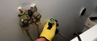
What natural grounding agents can be used?
For private houses, it is not prohibited to use natural grounding conductors as protective grounding. A good grounding system is communications made from metal pipes laid into houses. Such metal pipes for water supply and sewerage have good resistance to spreading.
These communications are buried below the freezing depth of the soil, so they do not dry out and are of constant importance. The reinforcement of a concrete foundation can also serve as an excellent grounding conductor, but provided that the reinforcement is connected to each other by welding and is in no case fastened with wire.
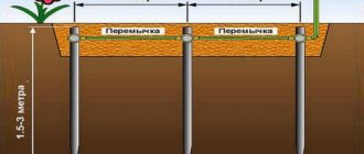
Nowadays, few people use metal pipes for communication; plastic pipes are increasingly used. Therefore, protective grounding devices are installed for protective grounding. Such structures can be rods driven into the ground one and a half meters apart and connected to each other by welding.
Type of protective grounding device
These ground electrode designs are simple and easy to install. If the grounding resistance is insufficient, additional rods are driven in to achieve normal spreading resistance. The grounding device is installed 2 meters from the building; the rods can be driven in a straight line or in the form of a closed loop.
On dry ground you need to use long grounding leads.
For wet soils, the grounding device is made of thick metal so that corrosion does not destroy the structure.
All ends of the rods are welded with 6 mm² wire. The rod closest to the building partially remains on the surface and is led into the house with a stranded copper wire. The entire structure of rods is driven into a pre-dug ditch and, after connecting them by welding, is covered with earth.
Initial data for calculating grounding
Before starting the arrangement of grounding, the calculation of which needs to be carried out, it is necessary to decide in advance on such initial data as:
- Linear dimensions of steel pins driven into the ground.
- The distance between them (installation pitch).
- Permissible immersion depth.
- Characteristics of the soil at the grounding site.
Additional note: Before carrying out the calculation, you will also need to know the value of the soil resistance Ohm at the installation site.
When determining it, it is important to remember that it varies greatly from place to place and largely depends on the climate zone to which the region belongs. In addition to these data, you will have to take into account the configuration and material of the workpieces from which the finished structure is welded (either a regular steel corner or a wide copper strip).
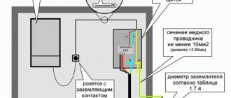
According to the PUE, the minimum dimensions of elements for a triangular or linear contour structure should be:
- strip - section 48 mm2;
- corner 4x4 mm;
- round bar – cross-section 10 mm2;
- steel pipe with a diameter of 2.5 cm with walls at least 3.5 mm thick.
Useful note: The minimum length of the pins is calculated taking into account the technical requirements (the need to obtain the required resistance to drainage into the ground).
In accordance with these requirements, it is chosen to be at least 2-2.5 meters. The distance between adjacent immersion points of the rods must be a multiple of their length. Depending on the size and configuration of the site for arranging the storage unit, the structural elements are installed either in a row or in the form of a regular triangle (sometimes a square shape is chosen for this). The methods used in this case for calculating various charger options aim to obtain data on the number of rods and the parameters of the connecting strip (its length and cross-section).
Grounding a private home: isn't this an unnecessary concern?
This is a question many novice homeowners ask. Our answer will probably not surprise you: grounding is not an unnecessary concern. Moreover, grounding is a necessity! We will try to justify this need without referring you to regulatory documents and without juggling with specific terms.
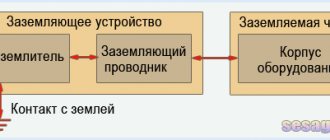
First of all, it is probably necessary to say in clear language what grounding is.
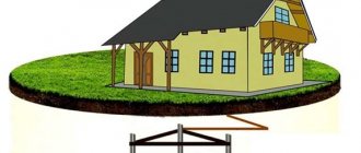
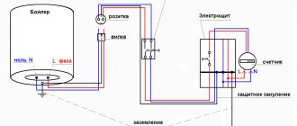
So, grounding is a connection using a conductor of the housings of the electrical equipment in the house with a grounding loop hidden in the ground.
This is the standard structure of grounding installed in a house
Calculation of grounding device elements
Determination of the parameters of the conductors used in the design of any ground electrode is carried out taking into account the following considerations:
- The length of the metal rods or pins greatly determines the effectiveness of the entire protective grounding system.
- The length of the elements of metallic bonds is also of great importance.
- The linear dimensions of these structural components determine the material consumption, as well as the total costs of arranging the charger.
- The resistance of vertically driven electrodes is primarily determined by the length.
- Their transverse dimensions do not have a significant impact on the quality and effectiveness of the protection provided.
Please note: The procedure for selecting the cross-section of conductors is determined in the PUE, since this indicator characterizes resistance to corrosion (electrodes should last 5-10 years).
In addition, you should always remember the “golden” rule, according to which the more metal blanks are provided in the circuit, the better the safety characteristics of the circuit.
Installation diagram of a single vertical ground electrode
It should also be taken into account that measures to organize grounding cannot be called an easy task. With a large number of system components, the volume of excavation work increases. And the decision on the specific method to improve the quality of grounding (due to the length or number of electrodes) remains up to the performer himself.
In any case, when arranging a memory of any type, it is recommended to adhere to the following rules:
- the rods must be driven in to a mark at least 50 centimeters below the soil freezing level;
- this arrangement will allow us to take into account seasonal factors and eliminate their influence on the performance of the protective system;
- the distance between the vertically driven elements depends on the shape of the chosen structure and the length of the rods themselves.
To correctly select this indicator, it is recommended to use reference tables.
Table for determining the parameters of grounding electrodes
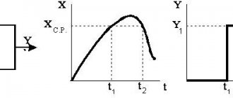
In order to reduce the volume of upcoming calculations (simplify them), it is first desirable to determine the value of the resistance to the flow of short-circuit currents for a single rod.
Taking into account the influence exerted on the desired value by horizontal structural elements, the resistance for vertical pins is calculated using the following formula:
If the mounted charger is installed in heterogeneous soil (its other name is two-layer), the resistivity can be determined as follows:
where Ψ is the so-called “seasonal” coefficient;
ρ1 and ρ2 – resistivity of soil layers (upper and lower layers, respectively), taken into account in calculations in Ohms per meter;
H – thickness of the soil layer in meters located in the upper part of the earth cover;
t – depth of vertical pins or rods (it corresponds to the depth of the prepared trench), equal to 0.7 meters.
The number of rods sufficient to obtain effective grounding (horizontal components are not taken into account yet) is determined as follows:
where Rн is the spreading resistance standardized by PTEEP.
Taking into account the horizontal elements of the charger, the formula for determining the number of vertical pins takes the following form:
where ηв is understood as the coefficient of utilization of the structure, indicating the mutual influence of the drainage currents of various individual elements on each other.
Additional information: When arranging a system of linearly arranged pins, it should be remembered that in this case their mutual influence is especially strong.
As the installation step of these elements of the protective circuit decreases, its overall resistance to current flow increases noticeably. The number of elements of the grounding structure obtained from the results of the described calculations should be rounded to a larger value.
Online grounding calculations can be automated if you use a special online calculator developed for this on our resource.
Participation in the calculation formula
In the formula for calculating grounding for a multi-electrode grounding conductor (grounding loop), the utilization factor is in the denominator.
The coefficient for identical vertical grounding conductors has the following values:
- from 1 (i.e. does not affect the grounding resistance) - with a mutual distance between the grounding electrodes equal to their double depth and with a small number of them
- up to 1/N (i.e. additional electrodes do not make any contribution to reducing the grounding resistance) - with a distance between grounding electrodes approaching 1/30 of their depth
Example of grounding calculation
As a “classical” example of calculating grounding, let’s consider a charger option taking into account the given initial data, that is, we will carry out calculations for a single metal pin. Let us immediately make a reservation that such simple designs are used when organizing the re-grounding of high-voltage supports. In the situation under consideration, according to the provisions of the PUE (see clause 1.7.103.), the current flow resistance cannot be more than 15, 30 and 60 Ohms for voltages of 660, 380 and 220 Volts, respectively.
Calculation of a single grounding element for a 380 Volt overhead line support
According to the previously discussed method, first, using the table, select the type of vertical pin with the following characteristics:
- Material – steel.
- Shape: round rod with a diameter of 16 mm.
- Length L - 2.5 meters.
Please note: Semi-solid clay with a resistivity ρ equal to 60 Ohm per meter is selected as soil in accordance with the table.
The depth of the trench is taken to be half a meter. Then, from the same table, the correction factor entered for the average climatic zone is found. Its value for the actual length of the rods is up to 2.5 meters, taking into account soil freezing in the given area, is ψ = 1.45. The normalized resistance indicator for this type of charger is 30 Ohms. The next indicator, soil resistivity, is found by the formula:
ρ (in fact) = ψ•ρ = 1.45x60 = 87 Ohm•meter
The resulting calculated data looks like this:
- the penetration of a single pin into the ground is h = 0.5l + t = 0.5x2.5 + 0.5 = 1.75 meters;
- its resistance for our example (see formulas above) is no more than 30 Ohms, which corresponds to the requirements of the PUE for a given voltage.
When one grounding pin is not enough to support an overhead line, it is allowed to add one more or even several rods. In this case, a different technique will be required, used for a linear outline or a triangular design.
TABLE OF CONTENTS
Part 1
1. General provisions 2. Methods for checking the status of the memory 2.1. Checking the implementation of memory elements 2.1.1. Visual check of the memory 2.1.2. Determination of the actual memory circuit 2.2. Checking the connection of grounding conductors with grounded elements, as well as natural grounding conductors with a charger 2.3. Checking the corrosion state of charger elements located in the ground 2.4. Measuring the resistance of chargers of substations and power lines 2.4.1. Measuring the resistance of substation chargers 2.4.2. Measuring the resistance of grounding conductors of overhead line supports 2.5. Measuring touch voltage 2.6. Checking the voltage at the substation charger when a ground fault current drains from it 2.7. Checking the condition of breakdown fuses 2.8. Checking the phase-zero circuit in electrical installations up to 1 kV
with solid neutral grounding
Part 2
3. Determination of the level of interference from external electromagnetic disturbances 4. Safety measures when monitoring the charger 5. Documentation for the charger of an electrical installation 6. Recommendations for repairing and strengthening the charger Appendix 1. Measuring equipment for monitoring the electrical parameters of the charger Appendix 2. An example of determining a real charger circuit using measuring complex KDZ-1 Appendix 3. Selection of the seasonal coefficient, measurement of the electrochemical potential and determination of the presence of stray currents Appendix 4. Determination of the resistance of the artificial grounding system of an electrical installation without taking into account outgoing communications Appendix 5. Numerical calculation of the electrical installation's charger Appendix 6. Passport for the grounding device of the power facility Appendix 7. Protocol for checking the condition of grounding devices
Soil resistivity
The calculation of a protective grounding device depends on many conditions, among which the main ones that are used in further calculations can be identified:
- Soil resistance;
- Electrode material;
- Electrode laying depth;
- Location of grounding conductors relative to each other;
- Weather.
The soil itself, with a few exceptions, has low electrical conductivity. This characteristic changes depending on the moisture content, since water with salts dissolved in it is a good conductor. Thus, the electrical properties of the soil depend on the amount of moisture contained, the salt composition and the properties of the soil to retain moisture.
Soil structure
Common soil types and their characteristics
| Soil type | Specific resistance ρ, Ohm•m |
| Rock | 4000 |
| Loam | 100 |
| Chernozem | 30 |
| Sand | 500 |
| Sandy loam | 300 |
| Limestone | 2000 |
| garden soil | 50 |
| Clay | 70 |
The table shows that the resistivity can differ by several orders of magnitude. In real conditions, the situation is complicated by the fact that at different depths the type of soil can be different and without clearly defined boundaries between the layers.
Electrode material
This part of the calculations is the simplest, since only a few types of materials are used in the manufacture of grounding:
- Steel;
- Copper;
- Copper-plated steel;
- Cink Steel.
Copper in its pure form is not used due to its high cost; the most commonly used materials are pure and galvanized steel. Recently, grounding systems that use steel coated with a layer of copper have become increasingly common. Such electrodes have the lowest resistance, which has good stability over time, since the copper layer resists corrosion well.
Uncoated steel has the worst characteristics, since a layer of corrosion (rust) increases the contact resistance at the electrode-soil interface.
Copper electrodes
Bookmark depth
The linear length of the boundary between the electrode and the ground and the size of the earth layer that participates in the current flow circuit depend on the depth of placement of the electrodes. The larger this layer, the lower the resistance value it will have.
This characteristic is the least obvious and difficult to understand. You should know that each grounding electrode has some influence on its neighbors, and the closer they are located, the less effective they will be. The exact justification of the effect is quite complex; you just need to take it into account during calculations and construction.
It is easier to explain the dependence of efficiency on the number of electrodes. Here we can give an analogy with parallel connected resistors. The more there are, the lower the total resistance.
Arrangement of grounding conductors in one row
Weather
The grounding device has the best parameters at high soil moisture. In dry and frosty weather, soil resistance increases sharply and when certain conditions are reached (complete drying or freezing) it reaches its maximum value.
Note! In order to minimize the influence of weather conditions, the depth of the electrodes should be below the maximum freezing depth in winter or reach the aquifer to prevent drying out.
Important! Subsequent calculations must be made for the worst operating conditions, since in all other cases the grounding resistance will decrease.
We invite you to familiarize yourself with: Grounding calculation. How to perform calculations for the contour of a private house
To calculate grounding resistance, there are special formulas and methods that describe dependencies on the described factors. They are presented on the “Grounding calculation” page.
The parameter determines the level of “electrical conductivity” of the earth as a conductor = how well the electric current coming from the ground electrode will flow in such an environment. The smaller this value is, the lower the grounding resistance will be.
Specific electrical resistivity of soil (Ohm*m) is a measured value that depends on the composition of the soil, the size and density of its particles adhering to each other, its humidity and temperature, the concentration of soluble chemicals in it (salts, acidic and alkaline residues).
A table of approximate values “soil resistivity” is usually used, because its accurate measurement is possible only during special geological survey work.
To measure this value, an ohmmeter is used - a device that changes resistance. In this case, devices for determining grounding resistance must have certain characteristics. The most important thing: very low input conductivity. The measurement range of such devices is extremely small: usually it ranges from 1 to 1000 Ohms. The measurement accuracy in analog instruments does not exceed 0.5–1 Ohm, and in digital instruments - up to 0.1 Ohm.
Despite the widespread spread of Chinese and European devices, the most popular remains the M416, developed in the USSR. The device has four measurement ranges: from 0 to 10 Ohms, from 0.5 to 50, from 2 to 200 and from 100 to 1000. The device runs on three AA batteries. Despite this, it is difficult to call it mobile - the dimensions of the case are not very comfortable.
A more advanced version is F4103 - an industrial ohmmeter with a high input resistance. It is even less transportable, but has a greater number of measurement ranges. A big plus of such a device: it works with a huge range of signals (from direct and pulsating current to alternating current with a frequency of 300 Hz). The user will also be pleased with the operating temperature range: from –25 to 55 degrees Celsius.
There are two documents that regulate the standards for grounding resistance in a circuit and other indicators. The first is the PUE (Electrical Installation Rules), which are relied upon when carrying out acceptance control. Operational measurements must comply with the Rules for the Technical Operation of Consumer Electrical Installations (PTEEP).
In both sets of rules, there is a division of circuits into several types - these must be taken into account before measuring ground resistance. They differ depending on the voltage used in the network and the type of circuit. There are three types of circuits:
- For substations and distribution points where the voltage does not exceed 1000 volts (regardless of whether the network uses alternating current or direct current).
- For overhead power lines (power lines) that transmit current with a voltage of less than 1000 volts.
- For electrical installations with the same maximum permissible voltage used for industrial or domestic purposes.
Results and conclusions
Grounding is an important element of an electrical circuit that provides protection against short circuits, electric shock or lightning strikes in one of its sections. The key indicator here is resistance: the lower it is, the more current the circuit will “carry” and the lower the likelihood of a serious shock or damage to the equipment.
Control standards that are designed to check the quality of grounding and the operation of the circuit under full load conditions cannot be neglected. Procedures are carried out both immediately after the creation of the chain and during its use. The frequency of checks depends on the load on the network and the purpose for which the circuit is used.
The norms of resistance are not different at all. There are three types of standards: for power lines, transformers and electrical installations. As the operating voltage increases, the maximum resistance value increases exponentially. A number of specific indicators are also taken into account (for example, soil conductivity). Based on it, you can obtain the maximum regulated resistance.
The main ways to increase the efficiency of the ground electrode is to use different conductor configurations. The key task is to maximize the area of direct contact of the circuit with the ground. For this, one or more conductors are used. In the latter case, they can be connected both in series and in parallel.
Also, to measure the resistance of the grounding loop, it is important to know the correction factors - for example, when calculating the minimum permissible grounding resistance, the specific content of the material in the soil and the re-grounding resistance are also taken into account. To obtain this indicator you need to use special equipment.
Tags: grounding, full, resistance, formula
« Previous entry