b
Rice. 1.7.5. TT system of alternating (a) and direct (b) current. The exposed conductive parts of the electrical installation are grounded using grounding that is electrically independent of the neutral grounding conductor: 1 - neutral grounding conductor of the alternating current source; 1-1 — ground electrode of the DC source output; 1-2 - ground electrode of the middle point of the DC source; 2 - open conductive parts; 3 - grounding conductor of open conductive parts of the electrical installation; 4 - power supply
1.7.5. Solidly grounded neutral - the neutral of a transformer or generator connected directly to the grounding device. The output of a single-phase alternating current source or the pole of a direct current source in two-wire networks, as well as the midpoint in three-wire DC networks, can also be solidly grounded.
1.7.6. Isolated neutral - the neutral of a transformer or generator, not connected to a grounding device or connected to it through a high resistance of signaling, measuring, protection and other similar devices.
1.7.7. Conductive part is the part that can conduct electric current.
1.7.8. Current-carrying part is a conductive part of an electrical installation that is under operating voltage during its operation, including the neutral working conductor (but not PEN
- conductor).
1.7.9. An exposed conductive part is a conductive part of an electrical installation that is accessible to touch, not normally energized, but which may become energized if the main insulation is damaged.
1.7.10. Third party conductive part - a conductive part that is not part of the electrical installation.
1.7.11. Direct touch is electrical contact of people or animals with live parts.
1.7.12. Indirect touch is electrical contact of people or animals with exposed conductive parts that become energized when the insulation is damaged.
1.7.13. Protection against direct contact - protection to prevent contact with live parts.
1.7.14. Protection against indirect contact - protection against electric shock when touching exposed conductive parts that become live when the insulation is damaged.
The term insulation failure should be understood as a single insulation failure.
1.7.15. Ground electrode - a conductive part or a set of interconnected conductive parts that are in electrical contact with the ground directly or through an intermediate conductive medium.
1.7.16. An artificial grounding conductor is a grounding conductor specially made for grounding purposes.
1.7.17. Natural grounding - a third-party conductive part that is in electrical contact with the ground directly or through an intermediate conducting medium, used for grounding purposes.
1.7.18. Grounding conductor is a conductor connecting the grounded part (point) to the ground electrode.
1.7.19. Grounding device - a combination of grounding conductors and grounding conductors.
1.7.20. Zero potential zone (relative ground) is a part of the earth located outside the zone of influence of any ground electrode, the electric potential of which is assumed to be zero.
1.7.21. Spreading zone (local ground) is the ground zone between the ground electrode and the zero potential zone.
The term ground used in the chapter should be understood as the ground in the spreading zone.
1.7.22. A ground fault is an accidental electrical contact between live parts and the ground.
1.7.23. The voltage on the grounding device is the voltage that occurs when current flows from the ground electrode into the ground between the point of current input into the ground electrode and the zero potential zone.
1.7.24. Touch voltage is the voltage between two conductive parts or between a conductive part and the ground when simultaneously touched by a person or animal.
Expected touch voltage - the voltage between simultaneously accessible conductive parts when a person or animal does not touch them
1.7.25. Step voltage is the voltage between two points on the surface of the earth, at a distance of 1 m from one another, which is taken to be equal to the length of a person’s step.
1.7.26. The resistance of the grounding device is the ratio of the voltage on the grounding device to the current flowing from the grounding device into the ground.
1.7.27. Equivalent resistivity of earth with a heterogeneous structure is the specific electrical resistance of earth with a homogeneous structure, in which the resistance of the grounding device has the same value as in earth with a heterogeneous structure.
The term resistivity, used in the chapter for earth with a heterogeneous structure, should be understood as equivalent resistivity.
1.7.28. Grounding is an intentional electrical connection of any point in the network, electrical installation or equipment with a grounding device.
1.7.29. Protective grounding is grounding performed for electrical safety purposes.
1.7.30. Working (functional) grounding - grounding of a point or points of live parts of an electrical installation, performed to ensure the operation of the electrical installation (not for electrical safety purposes).
1.7.31. Protective grounding in electrical installations with voltages up to 1 kV is a deliberate connection of open conductive parts with a solidly grounded neutral of a generator or transformer in three-phase current networks, with a solidly grounded output of a single-phase current source, with a grounded source point in direct current networks, performed for electrical safety purposes.
1.7.32. Potential equalization is the electrical connection of conductive parts to achieve equality of their potentials.
Protective potential equalization is potential equalization performed for electrical safety purposes.
The term potential equalization used in the chapter should be understood as protective potential equalization.
1.7.33. Potential equalization is a reduction in the potential difference (step voltage) on the surface of the earth or floor using protective conductors laid in the ground, in the floor or on their surface and connected to a grounding device, or by using special earth coverings.
1.7.34. Protective ( RE
) conductor - a conductor intended for electrical safety purposes.
Protective grounding conductor is a protective conductor designed for protective grounding.
Protective potential equalization conductor - a protective conductor designed for protective potential equalization.
Neutral protective conductor is a protective conductor in electrical installations up to 1 kV, intended for connecting open conductive parts to the solidly grounded neutral of the power source.
1.7.35. Zero working (neutral) conductor ( N
) - a conductor in electrical installations up to 1
kV
, intended for powering electrical receivers and connected to a solidly grounded neutral of a generator or transformer in three-phase current networks, with a solidly grounded output of a single-phase current source, with a solidly grounded source point in DC networks.
1.7.36. Combined zero protective and zero working ( PEN
) conductors - conductors in electrical installations with voltages up to 1
kV
, combining the functions of the zero protective and zero working conductors.
1.7.37. Main grounding bus - a bus that is part of the grounding device of an electrical installation up to 1 kV
and designed for connecting several conductors for the purpose of grounding and potential equalization.
1.7.38. Protective automatic power off - automatic opening of the circuit of one or more phase conductors (and, if required, the neutral working conductor), performed for electrical safety purposes.
The term automatic power off used in this chapter should be understood as protective automatic power off.
1.7.39. Basic insulation is the insulation of live parts, including protection from direct contact.
1.7.40. Additional insulation - independent insulation in electrical installations with voltages up to 1 kV
, performed in addition to the main insulation for protection against indirect contact.
1.7.41. Double insulation - insulation in electrical installations with voltages up to 1 kV
, consisting of main and additional insulation.
1.7.42. Reinforced insulation - insulation in electrical installations with voltages up to 1 kV
, providing a degree of protection against electric shock equivalent to double insulation.
1.7.43. Extra-low (small) voltage ( ELV
) - voltage not exceeding 50
V
AC and 120
V
DC.
1.7.44. Isolation transformer - a transformer whose primary winding is separated from the secondary windings by means of protective electrical separation of circuits.
1.7.45. Safety isolation transformer is an isolation transformer designed to supply circuits with extra-low voltage.
1.7.46. Protective shield is a conductive shield designed to separate an electrical circuit and/or conductors from live parts of other circuits.
1.7.47. Protective electrical separation of circuits - separation of one electrical circuit from other circuits in electrical installations with voltages up to 1 kV
by using:
double insulation;
main insulation and protective screen;
reinforced insulation
1.7.48. Non-conducting (insulating) rooms, zones, sites - rooms, zones, sites in which (in which) protection from indirect contact is provided by high resistance of the floor and walls and in which there are no grounded conductive parts.
Precautions against direct contact
1.7.67. Basic insulation of live parts must cover the live parts and withstand all possible impacts to which it may be subjected during its operation. Removal of insulation should only be possible by destroying it. Paint and varnish coatings are not insulation that protects against electric shock, except in cases specifically specified in the technical specifications for specific products. When performing insulation during installation, it must be tested in accordance with the requirements of Chapter. 1.8.
In cases where basic insulation is provided by an air gap, protection from direct contact with live parts or approaching them at a dangerous distance, including in electrical installations with voltages above 1 kV
, must be carried out by means of shells, fences, barriers or placement out of reach.
1.7.68. Fencing and shells in electrical installations with voltage up to 1 kV
must have a degree of protection of at least
IP 2X
, except in cases where large clearances are necessary for the normal operation of electrical equipment.
Guards and shells must be securely fastened and have sufficient mechanical strength.
Entering the fence or opening the shell should be possible only with the help of a special key or tool or after removing the voltage from live parts. IP 2X must be installed.
, the removal of which should also be possible only with the help of a special key or tool.
1.7.69. Barriers are designed to protect against accidental contact with live parts in electrical installations with voltages up to 1 kV
or approaching them at a dangerous distance in electrical installations with voltages above 1
kV
, but do not exclude deliberate touching and approaching live parts when bypassing the barrier. Removal of barriers does not require the use of a wrench or tool, but they must be secured so that they cannot be removed inadvertently. Barriers must be made of insulating material.
1.7.70. Placement out of reach for protection from direct contact with live parts in electrical installations with voltage up to 1 kV
or approaching them at a dangerous distance in electrical installations with voltages above 1
kV
can be applied if it is impossible to carry out the measures specified in 1.7.68-1.7.69 or their insufficiency.
In this case, the distance between conductive parts accessible to simultaneous touch in electrical installations with voltages up to 1 kV
must be at least 2.5
m.
Within the reach zone there should be no parts that have different potentials and are accessible to simultaneous touch.
In the vertical direction, the reach zone in electrical installations with voltages up to 1 kV
should be 2.5
m
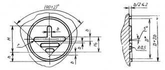
from the surface on which people are located (Fig. 1.7.6).
The indicated dimensions do not take into account the use of auxiliary equipment (for example, tools, ladders, long objects).
1.7.71. Installation of barriers and placement out of reach is only permitted in areas accessible to qualified personnel.
1.7.72. In electrical rooms of electrical installations with voltage up to 1 kV
Protection from direct contact is not required if the following conditions are met simultaneously:
these rooms are clearly marked and can only be accessed with a key;
it is possible to freely exit the premises without a key, even if it is locked from the outside;
The minimum dimensions of service passages correspond to Ch. 4.1.
Rice. 1.7.6. Reach zone in electrical installations up to 1 kV:
S
— a surface on which a person can be;
IN
is the base of the surface
S
;
- the boundary of the reach zone of live parts by the hand of a person located on the surface S
;
0,75; 1,25; 2,50 m
— distances from the edge of the surface
S
to the boundary of the reach zone
Requirements for grounding live parts
Requirements for grounding live parts
Grounding of live parts is carried out in order to protect workers from electric shock in the event of erroneous supply of voltage to the place of work.
It is necessary to apply grounding to live parts immediately after checking the absence of voltage. Portable grounding connections must first be connected to the ground, and then, after checking that there is no voltage, applied to live parts.
Portable ground connections should be removed in the reverse order: first remove them from live parts, and then disconnect them from the ground.
Operations for applying and removing portable groundings are carried out wearing dielectric gloves using an insulating rod in electrical installations with voltages above 1000 V. The clamps of the applied portable groundings should be secured using the same rod or directly with hands wearing dielectric gloves.
Grounding of live parts in electrical installations of substations
and in distribution devices
In electrical installations with voltages above 1000 V, grounding is applied to the current-carrying parts of all phases and poles of the section of the electrical installation that is disconnected for work on all sides from which voltage can be supplied, with the exception of busbars that are disconnected for work, to which it is sufficient to apply one grounding.
When working in a switchgear, it is not necessary to apply grounding connections at the opposite ends of the lines supplying this device, except in cases where during the work it is necessary to remove the grounding from the line inputs.
The applied groundings can be separated from the live parts on which work is directly performed by disconnected switches, disconnectors, separators or load switches, removed fuses, dismantled busbars or wires.
Grounding is additionally applied to live parts directly at the workplace in cases where these parts may be under induced voltage (potential) that can cause electric shock, or they may be supplied with voltage above 42 V AC and 110 V DC from an external source (welding machine, lighting networks, etc.).
Portable grounding connections applied to live parts must be separated from live parts under voltage by a visible break. Ground connections should be placed in areas that are free of paint.
In closed switchgear, portable grounding connections are applied to live parts in designated locations. These areas are cleared of paint and bordered with black stripes.
In closed switchgear and open switchgear, the places where portable grounding connections are connected to the grounding main or to grounded structures must be cleared of paint and adapted for fastening.
Grounding is not required when working on electrical equipment if buses, wires and cables through which voltage can be supplied are disconnected from all sides; unless voltage can be applied to it by reverse transformation or from an external source and provided that no voltage is induced on the equipment. The ends of the disconnected cables must be short-circuited and grounded.
In electrical installations with voltages above 1000 V, one person with a group of at least IV
from operational or operational maintenance personnel;
Portable grounding must be applied by two persons from operational or operational maintenance personnel with electrical safety groups not lower than IV
and III. The second person with a group not lower than III can be from the repair staff, and he must undergo training and be familiar with the electrical installation diagram; one person with a group of at least III from the operational or operational-repair personnel can disconnect the grounding knives and remove portable grounding connections.
In electrical installations with voltages up to 1000 V, all operations on applying and removing grounding are allowed to be performed by one person with an electrical safety group but lower than III from the operational or operational repair personnel.
Temporary removal and re-application of groundings is carried out by operational personnel or, under their supervision, by a member of a team with an electrical safety group of at least III.
In electrical installations with voltages above 1000 V without local operating personnel, temporary removal and reapplication of grounding in the absence of a permitting one can be carried out by the responsible manager or work performer or, under his supervision, by a member of a team with a group not lower than III.
When issuing a work order, permission to temporarily remove groundings is entered in the “Separate instructions” line with a record of where and for what purpose this operation is required.
Measures to protect against direct and indirect contact
1.7.73. Extra-low (small) voltage ( ELV
) in electrical installations with voltages up to 1
kV
can be used to protect against electric shock due to direct and/or indirect contact in combination with protective electrical separation of circuits or in combination with automatic power off.
As a power supply for ELV
in both cases, a safe isolation transformer should be used in accordance with GOST 30030 “Isolation transformers and safety isolation transformers” or another
SLV
that provides an equivalent degree of safety.
Current-carrying parts of ELV
must be electrically separated from other circuits so as to provide electrical separation equivalent to that between the primary and secondary windings of an isolation transformer.
ELV circuit conductors
, as a rule, should be laid separately from higher voltage conductors and protective conductors, either separated from them by a grounded metal shield (sheath), or enclosed in a non-metallic sheath in addition to the main insulation.
Plugs and sockets of plug connectors in ELV circuits should not allow connection to sockets and plugs of other voltages. Plug sockets must be without protective contact. SNN values
Above 25
V
AC or 60
V
DC, protection against direct contact must also be provided by guards or enclosures or insulation corresponding to a test voltage of 500
V
AC for 1
min
.
1.7.74. When using SNN
in combination with electrical separation of circuits, exposed conductive parts shall not be intentionally connected to the earthing conductor, protective conductors or exposed conductive parts of other circuits and to extraneous conductive parts, unless the connection of the extraneous conductive parts to the electrical equipment is necessary and the voltage on these parts cannot exceed the value
of SNN
.
SNN
in combination with electrical separation of circuits, it should be used when, with the help of ELV, it is necessary to provide protection against electric shock in case of insulation damage not only in the
ELV
, but also in case of insulation damage in other circuits, for example, in the circuit feeding the source.
When using SNN
in combination with automatic power off, one of the terminals of the
ELV
and its housing must be connected to the protective conductor of the circuit feeding the source
1.7.75. In cases where the electrical installation uses electrical equipment with the highest operating (functional) voltage not exceeding 50 V AC or 120 V
direct current, such voltage can be used as a measure of protection against direct and indirect contact, if the requirements of 1.7.73-1.7.74 are met.
Occupational Safety and Health
Parts of electrical installations subject to grounding
According to the “Rules,” metal parts of electrical installations and equipment in all industrial premises and outdoor installations that may be energized due to failure of the insulation of electrical equipment are grounded. Parts to be grounded include: casings of devices, electrical machines and transformers, frames of distribution boards, casings of cable couplings, metal shells of wires and cables, metal casings of lamps, switches, plug sockets, etc.
Grounding of the above electrical installation elements is not required in the following cases:
a) at a rated voltage of 380 V and below AC and 440 V and below DC in rooms classified as without increased risk of electric shock, except in cases where simultaneous contact of operating personnel with electrical equipment and other grounded objects is possible;
b) at a rated voltage below 127 V AC and 110 V DC in all premises, except as provided by special rules.
Protective grounding is the connection to the ground electrode of metal parts of the installation isolated from live conductors. Performed to protect against dangerous voltages.
A grounding electrode is a metal conductor or a group of conductors (pipes, angle steel, plates, etc.) that are in direct contact with the soil and have a sufficiently high conductivity.
The set of grounding conductors and grounding wires connecting the grounded parts of an electrical installation to the grounding conductor is called a grounding device.
Electrical installations with voltages up to 1000 V are allowed with both a solidly grounded and an insulated neutral, and DC electrical installations with a solidly grounded or insulated midpoint.
A solidly grounded neutral is a transformer or generator neutral connected to a grounding device directly or through low resistance.
An isolated neutral is a neutral that is not connected to a grounding device or is connected through devices that have high resistance.
Networks with voltages up to 1000 V with an insulated neutral, connected through transformers with networks with voltages above 1000 V, must be protected from the danger arising from damage to the insulation between the high and low voltage windings of the transformer, using a breakdown fuse installed in the neutral or phase on the low side transformer voltage. The total resistance of the grounding device should not be more than 4 ohms.
When the power of generators and transformers is 100 kVA or less, grounding devices must have a resistance of no more than 10 ohms.
In four-wire AC networks, solid grounding of the neutral is mandatory.
In electrical installations up to 1000 V with a solidly grounded neutral, a metal connection is required between electrical equipment housings and equipment with a grounded neutral neutral (grounding) wire (Fig. 69).
The neutral wire is the network wire connected to the grounded neutral of the transformer or generator.
The resistance of the grounding device in electrical installations with voltages up to 1000 V, to which the neutrals of generators or transformers are connected, should not be more than 4 ohms. The exception is grounding devices to which the neutrals of generators and transformers with a power of 100 kVA or less are connected. For such installations, the grounding resistance should not exceed 10 ohms.
The resistance of a grounding device is the sum of resistances, which consists of the resistance of the grounding device relative to the ground and the resistance of the grounding conductors.
Protective measures for indirect contact
1.7.76. The requirements for protection from indirect contact apply to:
1) housings of electrical machines, transformers, devices, lamps, etc.;
2) drives of electrical devices;
3) frames of distribution boards, control panels, panels and cabinets, as well as removable or opening parts, if the latter are equipped with electrical equipment with voltages higher than 50 V
AC or 120
V
DC (in cases provided for by the relevant chapters
of the PUE
- above 25
V
AC or 60
V
DC);
4) metal structures of switchgears, cable structures, cable couplings, shells and armor of control and power cables, sheaths of wires, sleeves and pipes of electrical wiring, shells and supporting structures of busbars (conductors), trays, boxes, strings, cables and strips on which reinforced cables and wires (except for strings, cables and strips along which cables with a neutralized or grounded metal sheath or armor are laid), as well as other metal structures on which electrical equipment is installed;
5) metal shells and armor of control and power cables and wires for voltages not exceeding those specified in 1.7.53, laid on common metal structures, including in common pipes, boxes, trays, etc., with cables and wires on higher voltages;
6) metal cases of mobile and portable electrical receivers;
7) electrical equipment installed on moving parts of machines, machines and mechanisms.
When automatic power-off is used as a protective measure, the specified exposed conductive parts must be connected to the solidly grounded neutral of the power supply in the TN
and grounded in
IT
and
TT
.
1.7.77. Does not need to be intentionally connected to the source neutral in a TN
and grounding in
IT
and
TT
:
1) housings of electrical equipment and devices installed on metal bases: structures, switchgears, switchboards, cabinets, frames of machines, machines and mechanisms connected to the neutral of the power source or grounded, while ensuring reliable electrical contact of these housings with the bases;
2) structures listed in 1.7.76, while ensuring reliable electrical contact between these structures and the electrical equipment installed on them, connected to the protective conductor;
3) removable or opening parts of the metal frames of switchgear chambers, cabinets, fences, etc., if electrical equipment is not installed on the removable (opening) parts or if the voltage of the installed electrical equipment does not exceed the values specified in 1.7.53;
4) reinforcement of insulators of overhead power lines and fasteners attached to it;
5) open conductive parts of electrical equipment with double insulation;
6) metal staples, fasteners, sections of pipes for mechanical protection of cables in places where they pass through walls and ceilings and other similar parts of electrical wiring with an area of up to 100 cm2
, including traction and branch boxes for hidden electrical wiring.
1.7.78. When performing automatic power off in electrical installations with voltage up to 1 kV
all exposed conductive parts must be connected to the solidly grounded neutral of the power source if a
TN
, and grounded if
an IT
or
TT
. In this case, the characteristics of the protective devices and the parameters of the protective conductors must be coordinated to ensure the normalized time for disconnecting the damaged circuit by the protective switching device in accordance with the rated phase voltage of the supply network.
In electrical installations in which automatic power off is used as a protective measure, potential equalization must be performed.
To automatically turn off the power, protective switching devices that respond to overcurrents or differential current can be used.
1.7.79. In TN
the time for automatic power off should not exceed the values specified in table. 1.7.1.
Table 1.7.1
Grounding. What is it and how to make it (part 1)
My story will consist of three parts.
1 part. Grounding (general information, terms and definitions)
Part 2. Traditional methods of constructing grounding devices (description, calculation, installation)
Part 3. Modern methods of constructing grounding devices (description, calculation, installation)
In the first part (theory), I will describe the terminology, the main types of grounding (purpose) and the requirements for grounding.
In the second part (practice) there will be a story about traditional solutions used in the construction of grounding devices, listing the advantages and disadvantages of these solutions. The third part (practice) will in a sense continue the second. It will contain a description of new technologies used in the construction of grounding devices. As in the second part, listing the advantages and disadvantages of these technologies. If the reader has theoretical knowledge and is only interested in practical implementation, it is better for him to skip the first part and start reading from the second part.
If the reader has the necessary knowledge and wants to get acquainted only with new products, it is better to skip the first two parts and immediately move on to reading the third.
My view of the described methods and solutions is to some extent one-sided. I ask the reader to understand that I do not put forward my material as a comprehensive objective work and express my point of view and my experience in it.
Some part of the text is a compromise between accuracy and the desire to explain in “human language”, so simplifications are made that can “harm the ears” of a technically savvy reader.
1 part. Grounding
In this part I will talk about terminology, the main types of grounding and the quality characteristics of grounding devices.
A. Terms and definitions B. Purpose (types) of grounding
B1. Working (functional) grounding B2. Protective grounding
B2.1. Grounding as part of external lightning protection B2.2. Grounding as part of the surge protection system (SPD) B2.3. Grounding as part of the electrical network
B. Quality of grounding. Grounding resistance.
IN 1. Factors affecting the quality of grounding
B1.1. Contact area of the ground electrode with the ground B1.2. Electrical resistance of soil (specific)
AT 2. Existing standards for grounding resistance B3. Calculation of grounding resistance
A. Terms and definitions
To avoid confusion and misunderstanding in the further story, I will start from this point. I will give the established definitions from the current document “Rules for the Construction of Electrical Installations (RUE)” in the latest edition (Chapter 1.7 in the seventh edition).
And I will try to “translate” these definitions into “simple” language.
Grounding
is an intentional electrical connection of any point in the network, electrical installation or equipment with a grounding device (PUE 1.7.28).
Soil is a medium that has the property of “absorbing” electric current. It is also a certain “common” point in the electrical circuit, relative to which the signal is perceived.
Grounding device
- a set of grounding conductors/grounding conductors and grounding conductors (PUE 1.7.19).
This is a device/circuit consisting of a grounding conductor and a grounding conductor connecting this grounding conductor to the grounded part of the network, electrical installation or equipment.
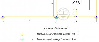
Can be distributed, i.e. consist of several mutually distant grounding conductors. In the figure it is shown with thick red lines:
Ground electrode
- a conductive part or a set of interconnected conductive parts that are in electrical contact with the ground (PUE 1.7.15).
The conductive part is a metal (current-conducting) element/electrode of any profile and design (pin, pipe, strip, plate, mesh, bucket,
etc.) located in the ground and through which electric current from the electrical installation “flows” into it. The configuration of the ground electrode (number, length, location of electrodes) depends on the requirements for it and the ability of the soil to “absorb” the electric current flowing/“flowing” from the electrical installation through these electrodes. In the figure it is shown with thick red lines:
Ground resistance
— the ratio of the voltage on the grounding device to the current flowing from the ground electrode into the ground (PUE 1.7.26).
Grounding resistance is the main indicator of a grounding device, determining its ability to perform its functions and determining its overall quality. Grounding resistance depends on the area of electrical contact of the ground electrode (grounding electrodes) with the ground (“draining” of current) and the electrical resistivity of the soil in which this ground electrode is mounted (“absorption” of current).
Ground electrode (ground electrode)
- conductive part in electrical contact with local ground (GOST R 50571.21-2000 clause 3.21)
I repeat: the conductive part can be a metal (current-carrying) element of any profile and design (pin, pipe, strip, plate, mesh, bucket,
etc.), located in the ground and through which the electric current “flows” into it from electrical installations. In the figure they are shown with thick red lines:
Below are definitions that are not found or not described accurately enough in standards and norms, and therefore have only my description.
Grounding loop
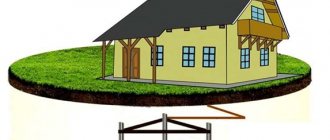
is the “popular” name for a ground electrode or grounding device, consisting of several grounding electrodes (groups of electrodes) connected to each other and mounted around an object along its perimeter/contour.In the figure, the object is indicated by a gray square in the center, and the ground loop is indicated by thick red lines:
The electrical resistivity of the soil
is a parameter that determines the level of “electrical conductivity” of the soil as a conductor, that is, how well the electric current from the grounding electrode will spread in such an environment. This is a measured value that depends on the composition of the soil, the size and density of its particles adhering to each other, humidity and temperature, and the concentration of soluble chemicals in it (salts, acidic and alkaline residues).
B. Purpose (types) of grounding
Grounding is divided into two main types according to the role it performs - working (functional) and protective. Also, various sources provide additional types, such as: “instrumental”, “measuring”, “control”, “radio”.
B1. Working (functional) grounding
This is the grounding of a point or points of live parts of an electrical installation, performed to ensure the operation of the electrical installation (not for electrical safety purposes) (PUE 1.7.30).
Working grounding (electrical contact with the ground) is used for the normal functioning of an electrical installation or equipment, i.e. for their operation in NORMAL mode.
B2. Protective grounding
This is grounding performed for electrical safety purposes (PUE 1.7.29).
Protective grounding ensures the protection of electrical installations and equipment, as well as the protection of people from the effects of dangerous voltages and currents that may occur during breakdowns, improper operation of equipment (i.e. in EMERGENCY mode) and during lightning strikes. Protective grounding is also used to protect equipment from interference during switching in the power supply network and interface circuits, as well as from electromagnetic interference induced from nearby equipment.
The protective purpose of grounding can be considered in more detail using two examples:
- as part of an external lightning protection system in the form of a grounded lightning rod
- as part of a surge protection system
- as part of the facility's electrical network
B2.1. Grounding as part of lightning protection
Lightning is a discharge or, in other words, a “breakdown” that occurs FROM the cloud TO the ground, when a charge of a critical value (relative to the ground) accumulates in the cloud.
Examples of this phenomenon on a smaller scale are “breakdown” (wiki) in a capacitor and gas discharge (wiki) in a lamp. Air is a medium with a very high resistance (dielectric), but the discharge overcomes it, because has great power. The discharge path follows areas of least resistance, such as water droplets in the air and trees. This explains the root-like structure of lightning in the air and the frequent strikes of lightning into trees and buildings (they have less resistance than the air in this gap). When it hits the roof of a building, lightning continues its path to the ground, also choosing areas with the least resistance: wet walls, wires, pipes, electrical appliances - thus presenting a danger to people and equipment located in this building.
Lightning protection is designed to divert lightning discharge from the protected building/object.
A lightning discharge, following the path of least resistance, enters a metal lightning rod above the object, then, along metal lightning rods located outside the object (for example, on walls), descends to the ground, where it diverges in it (I remind you: soil is a medium that has the property of “absorbing ” into itself an electric current). In order to make lightning protection “attractive” to lightning, as well as to prevent the spread of lightning currents from lightning protection parts (receiver and taps) into the object, its connection to the ground is made through a ground electrode having a low grounding resistance.
Grounding in such a system is a mandatory element, because it is this that ensures the complete and rapid transition of lightning currents into the ground, preventing their spread throughout the facility.
B2.2. Grounding as part of a surge protection system (SPD)
The SPD is designed to protect electronic equipment from a charge accumulated on any part of the line/network as a result of exposure to an electromagnetic field (EMF) induced from a nearby powerful electrical installation (or high-voltage line) or EMF arising from a close (up to hundreds of meters) discharge lightning.
A striking example of this phenomenon is the accumulation of charge on the copper cable of a home network or on the “forwarding” between buildings during a thunderstorm. At some point, the devices connected to this cable (computer network card or switch port) cannot withstand the “size” of the accumulated charge and an electrical breakdown occurs inside this device, destroying it (simplified). To “bleed off” the accumulated charge parallel to the “load,” an SPD is placed on the line in front of the equipment.
A classic SPD is a gas arrester (wiki), designed for a certain “threshold” of charge, which is less than the “safety factor” of the equipment being protected.
One of the electrodes of this arrester is grounded, and the other is connected to one of the line/cable wires. When this threshold is reached, a discharge occurs inside the spark gap between the electrodes. As a result, the accumulated charge is discharged into the ground (through grounding).
As in lightning protection, grounding in such a system is a mandatory element, because it is this that ensures the timely and guaranteed occurrence of a discharge in the SPD, preventing the charge on the line from exceeding a level that is safe for the equipment being protected.
B2.3. Grounding as part of the electrical network
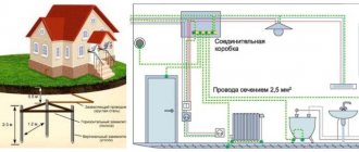
The third example of the protective role of grounding is ensuring the safety of humans and electrical equipment during breakdowns/accidents.
The simplest way to describe such a breakdown is a short circuit of the phase wire of the electrical network to the body of the device (short circuit in the power supply or short circuit in the water heater through the aqueous medium). A person who touches such a device will create an additional electrical circuit through which a current will flow, causing damage to internal organs in the body - primarily the nervous system and heart.
To eliminate such consequences, the housings are connected to a grounding conductor (to drain emergency currents into the ground) and automatic protective devices are used that turn off the current in a split second in an emergency.
For example, grounding of all cases, cabinets and racks of telecommunications equipment.
B. Quality of grounding. Grounding resistance.
For grounding to perform its functions correctly, it must have certain parameters/characteristics. One of the main properties that determine the quality of grounding is the resistance to current spreading (grounding resistance), which determines the ability of the grounding electrode (grounding electrodes) to transmit currents supplied to it from the equipment into the ground. This resistance has finite values and, ideally, is a zero value, which means the absence of any resistance when passing “harmful” currents (this guarantees their COMPLETE absorption by the soil).
IN 1. Factors affecting the quality of grounding
Resistance mainly depends on two conditions:
- area (S) of electrical contact of the ground electrode with the ground
- electrical resistance (R) of the soil itself in which the electrodes are located
B1.1. Contact area of the ground electrode with the ground.
The larger the area of contact between the ground electrode and the ground, the larger the area for the current to pass from this ground electrode into the ground (the more favorable conditions are created for the current to pass into the ground).
This can be compared to the behavior of a car wheel when turning. A narrow tire has a small contact area with the asphalt and can easily begin to slide along it, “sending” the car into a skid. A wide tire, and even a little flat, has a much larger contact area with the asphalt, providing reliable grip and, therefore, reliable control of movement. (The example turned out to be illiterate. Thanks to SVlad - comment: habrahabr.ru/post/144464/# comment_4854521) You can increase the contact area of the ground electrode with the ground either by increasing the number of electrodes, connecting them together (by adding the areas of several electrodes), or by increasing the size of the electrodes. When using vertical grounding electrodes, the latter method is very effective if the deep layers of the soil have lower electrical resistance than the upper ones.
B1.2. Electrical resistance of soil (specific)
Let me remind you: this is a quantity that determines how well the soil conducts current through itself.
The less resistance the soil has, the more efficiently/easier it will “absorb” the current from the ground electrode. Examples of soils that conduct electricity well are salt marshes or highly moist clay. The ideal natural environment for passing current is sea water. An example of a “bad” soil for grounding is dry sand.
(If interested, you can look at the table of soil resistivity values used in the calculations of grounding devices).
Returning to the first factor and the method of reducing grounding resistance in the form of increasing the depth of the electrode, we can say that in practice, in more than 70% of cases, soil at a depth of more than 5 meters has several times lower electrical resistivity than that of the surface, due to higher humidity and density . Groundwater is often found, which provides the soil with very low resistance. Grounding in such cases is very high quality and reliable.
AT 2. Existing standards for grounding resistance
Since the ideal (zero spreading resistance) cannot be achieved, all electrical equipment and electronic devices are created based on certain standardized values of grounding resistance, for example 0.5, 2, 4, 8, 10, 30 or more ohms.
For orientation, I will give the following values:
- for a substation with a voltage of 110 kV, the current flow resistance should be no more than 0.5 Ohm (PUE 1.7.90)
- When connecting telecommunications equipment
, grounding should usually have a resistance of no more than 2 or 4 ohms - For reliable operation of gas arresters in devices for protecting overhead communication lines
(for example, a local network based on a copper cable or a radio frequency cable), the grounding resistance to which they (the arresters) are connected must be no more than 2 Ohms. There are instances with a requirement of 4 ohms. - at the current source (for example, a transformer substation), the grounding resistance should be no more than 4 Ohms at a linear voltage of 380 V of a three-phase current source or 220 V of a single-phase current source (PUE 1.7.101)
- the grounding used to connect lightning rods
should have a resistance of no more than 10 ohms (RD 34.21.122-87, p.
- for private houses, with a connection to a 220 Volt / 380 Volt power supply: when using the TN-CS system, it is necessary to have local grounding with a recommended resistance of no more than 30 Ohms (I am guided by PUE 1.7.103)
- when using the TT system (isolating grounding from the neutral of the current source) and using a residual current device (RCD) with an operating current of 100 mA, it is necessary to have local grounding with a resistance of no more than 500 Ohms (PUE 1.7.59)
AT 3. Calculation of grounding resistance
To successfully design a grounding device that has the required grounding resistance, standard grounding configurations and basic formulas for calculations are usually used.
The ground electrode configuration is usually selected by the engineer based on his experience and the possibility of its (configuration) application at a particular facility.
The choice of calculation formulas depends on the selected grounding configuration. The formulas themselves contain the parameters of this configuration (for example, the number of grounding electrodes, their length, thickness) and the parameters of the soil of a particular object where the ground electrode will be located. For example, for a single vertical electrode this formula will be:
The accuracy of the calculation is usually low and again depends on the soil - in practice, discrepancies in practical results occur in almost 100% of cases. This is due to its (soil) great heterogeneity: it changes not only in depth, but also in area - forming a three-dimensional structure. Existing formulas for calculating grounding parameters can hardly cope with one-dimensional soil heterogeneity, and calculations in a three-dimensional structure involve enormous computing power and require extremely high operator training. In addition, to create an accurate soil map, it is necessary to carry out a large amount of geological work (for example, for an area of 10*10 meters it is necessary to make and analyze about 100 pits up to 10 meters long), which causes a significant increase in the cost of the project and is most often not possible.
In light of the above, the calculation is almost always a mandatory but indicative measure and is usually carried out on the principle of achieving a grounding resistance of “no more than.” The average values of soil resistivity, or their largest values, are substituted into the formulas. This provides a “margin of safety” and in practice is expressed in obviously lower (lower means better) grounding resistance values than expected during the design.
Construction of ground electrodes
When constructing grounding electrodes, vertical grounding electrodes are most often used.
This is due to the fact that horizontal electrodes are difficult to bury to a great depth, and at a shallow depth of such electrodes, their grounding resistance greatly increases (deterioration of the main characteristic) in winter due to the freezing of the top layer of soil, leading to a large increase in its specific electrical resistance. Steel pipes, pins/rods, angles, etc. are almost always chosen as vertical electrodes. standard rolled products having a large length (more than 1 meter) with relatively small transverse dimensions. This choice is due to the possibility of easily deepening such elements into the ground, unlike, for example, a flat sheet.
More details about construction in the following parts.
Continuation:
- Second part
- The third part
Alexey Rozhankov, technical specialist
The following materials were used in preparing this part:
- Publications on the website “Grounding on ZANDZ.ru”
- Rules for the Construction of Electrical Installations (PUE), part 1.7 as amended by the seventh edition (Google)
- GOST R 50571.21-2000 (IEC 60364-5-548-96) Grounding devices and electrical potential equalization systems in electrical installations containing information processing equipment (Google)
- Instructions for the installation of lightning protection of buildings and structures RD 34.21.122-87 (Google)
- Own experience and knowledge