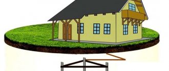
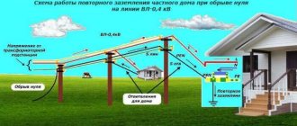
Re-grounding of VLI is a deliberate connection of the neutral wire with a grounding device in electrical installations up to 1 kV, which may have an electrical connection with the grounding device of the power supply. VLI is an overhead line on supports made of reinforced concrete or wood with self-supporting insulated wires (SIP). Below we will tell readers of the Sam Electric website how to properly re-ground overhead power lines and why it is needed.
What is it for?
Outdoor lighting system supports
Grounding for a network of outdoor lighting poles or overhead lines (0.4, 6-10, 20 and 35 kV) is of great importance, since it prevents the risk of electrical injury when coming into contact with structural elements in a situation where cable insulation is damaged. If there is grounding on a metal support of an outdoor lighting network or overhead line, the voltage “spreads” along the ground, thereby becoming safe for people. This indicator depends on the resistance of the soil in which the overhead line support is installed (0.4, 6-10, 20 and 35 kV). As a result, even if a violation of the overhead line insulation occurs somewhere, the structures will remain safe.
Under normal operating conditions, pin insulators mounted on supports will provide reliable insulation of all wires from structural elements. But there are situations when the voltage in the network significantly exceeds the voltage for which the overhead line was designed (0.4, 6-10, 20 and 35 kV). In such an overvoltage situation, a breakdown of the overhead line insulation is possible and, as a result, the network fails. In order to limit the value of overvoltage and improve safety, it is necessary to reduce the resistance for "current spreading". For this purpose, protective grounding is installed on overhead lines (0.4, 6-10, 20 and 35 kV) and supports for external lighting.
Section calculation
Calculating the required cross-section is quite simple and for this you will need to use the formula:
S = (Iset √tph) / 272
In this formula:
- Ist is the steady-state short circuit current.
- Tf is fictitious time.
If it is necessary to calculate grounding for a switchgear of one voltage, tf take the longest time value at the moment the protection relay of your installation is activated. In networks where there is a grounding neutral, the cross-section of the core must be calculated based on the short-circuit current of one phase.
Connection diagram for a single-phase electric meter
The connection diagram for a single-phase electric meter presented here is universal and equally suitable for installing a one- or two-tariff electricity meter, no matter the electronic or induction (mechanical) type, regardless of the brand and manufacturer, be it Neva, Energomera, Mercury, etc.
Almost any single-phase meter has four terminals for connecting wires. Depending on the brand and functionality of a particular electric meter, the terminals may be marked differently, but the order of connecting the wires to them is the same. Therefore, for convenience and versatility, we will number them in order in the diagram, from left to right from 1 to 4.
The input electrical cable entering an apartment or house in a single-phase network consists of two (phase and neutral) or three (phase, neutral, ground) wires.
To connect the electric meter and its proper operation, we need two wires - a phase and a working zero. The article “How to determine phase, zero and grounding yourself, using improvised means” will help you determine which of your conductors is phase and which is neutral?
Universal diagram for connecting wires to a single-phase electric meter
The diagram looks like this:
In the diagram you can see a single-phase electric meter located in the center, on the left there is an input power cable (phase and zero), on the right there are wires going out to the load, roughly speaking, the electricity recorded by the meter already flows through them, which through the protective automatics goes to your sockets , lamps, etc.
- The procedure for connecting wires to the terminals of a single-phase meter is as follows:
- Terminal “1” - Phase wire of the input cable (usually white, brown or black wire)
- Terminal “2” - Phase wire going to the load of an apartment or house (usually white, brown or black wire)
- Terminal “3” - Neutral wire of the input cable (usually blue or blue-blue wire)
- Terminal “4” - Neutral wire going to the load of an apartment or house (usually a blue or blue-blue wire)
A connection made according to this scheme is already sufficient for the correct operation of a single-phase meter in the home electrical network. A protective ground connection to the electric meter is not required. Additional terminals that may be on your model of a single-phase electric meter are auxiliary and serve to access service functions, maintenance, automation of energy metering, etc.
Connection diagram for a single-phase meter in an electrical panel
In a home electrical network, a single-phase electric energy meter is always installed and interacts with protective automation. All this equipment is usually located in a special box - an electricity metering and distribution panel (AMB).
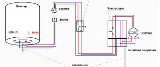
And of course, there are rules according to which a single-phase electric meter is connected. If you follow them, the simplest connection diagram for a single-phase meter should look like this:
As you can see, in front of the electric meter, it is necessary to install a single-pole automatic switch, the so-called “input circuit breaker”, into which the phase wire of the input cable enters and from it the phase enters terminal “1” of the electric meter, the working zero goes directly to terminal “3”, and protective grounding (protective zero) is connected directly to the zero bus.
The load in our example is a protective circuit breaker, to which you can connect a lighting group and a differential current circuit breaker (residual current circuit breaker, differential circuit breaker) to a group of sockets. The layout of your switchboard may be different, but the principle of connecting automation after a single-phase electric meter will be similar.
This is the simplest and most commonly used connection diagram for a single-phase electric meter recommended in the PUE (electrical installation rules).
Also, I would recommend considering a more refined, improved version of the connection diagram for a single-phase electric meter, which uses a two-pole input circuit breaker.
As you can see, in this circuit, not only the phase conductor passes through the two-pole circuit breaker, as in the first case, but also the neutral conductor of the input power cable.
Now, in the event of an emergency and the input circuit breaker is triggered, the neutral wire will also break, which, in some cases, may have a dangerous potential and this is not the only advantage of this connection scheme.
Remember, it is important to use a two-pole circuit breaker, and not two single-pole ones that are not combined!
For fire trucks
When considering portable ground connections for fire trucks, you will need to pay attention to the following important details:
- various designs of protective devices of this class have a standard design, designated as ZPS-25;
- The grounding conductor, pressed at both ends, is attached on one side using an oval ring-clamp to the barrel of the fire brace, and on the other - directly to the grounding pins driven into the ground;
- When installing a temporary protective structure, the requirements of current regulations regarding the parameters of grounding devices must be taken into account.
Depending on the composition of the set of equipment used and the presence of additional grounding devices, some provisions of the current rules are supplemented with special recommendations. In accordance with their requirements, situations are determined in which one or another type of remote loop grounding for fire engines is used.
How to do grounding correctly in an apartment
To answer this question, you need to understand what kind of protection system is installed in your home.
As a rule, in old Soviet-built houses the TN-C System was used, in which the neutral protective and neutral working conductors are combined into one PEN conductor, and they are combined throughout the entire system. You can recognize such a system by the two-core cable that is laid around the apartment and by the four-core cable in the common panel.
To be honest, how to properly do grounding in an apartment in an old building, then such a system only protects against short circuits and increases the likelihood of receiving an electric shock. Therefore, talking about protective grounding in this case is necessary with a certain degree of risk. There are several working options that reduce risks, but are not complete protection, and are done at your own peril and risk.
In modern apartment buildings, the TN-S system is used, in which the N and PE conductors are separated throughout the entire length from the substation to the consumer. This system is the safest and most preferred, but is used only in new electrical installations due to its high cost. Most houses now use the TN-CS system, in which the N and PE conductors after the substation are connected into one PEN wire, and then separated at the entrance to the building.
In this case, protective grounding can be organized at the stage of electrical installation using three-wire wires, grounded sockets and protective automatic equipment. When a phase hits the device body, the circuit breaker should trip. When touching live parts, the RCD should trip.
For electrical distribution, I advise you to choose a cable with three cores in double insulation, preferably VVG NG, for socket groups with a cross-section of 3 by 2.5 for light groups 3 by 1.5. One end of the wire is inserted under the free bolt of the distribution panel bus connected to the panel body, and the other - to the “grounding” contact of the socket. At the same time as assembling the apartment panel, electricians check the connection of the grounding wire in the common house panel.
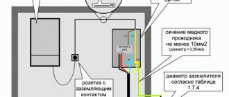
The protective grounding circuit in a bathroom apartment can be schematically represented as follows.
Rules and requirements for the ground loop
In order for the ground loop to work effectively, it must comply with certain rules:
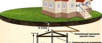
- The external contour should be located at a distance of at least 1 m and no more than 10 m from the house. The optimal distance is 2-4 m from the foundation.
- The depth of the electrodes is selected within 2-3 m. A part of the pin 20-25 cm long is left on the surface for connection with a strip.
- A bus with a cross-section of at least 16 square meters is laid from the input panel to the circuit. mm.
- The connection of the electrodes to each other is ensured only by welding. The connection in the panel can be made with bolts.
- The total system resistance should not exceed 4 ohms for 380 V and 8 ohms for 220 V.
The external ground loop is located in the ground, which implies increased requirements for its design. It should be located below the soil freezing level, because heaving of the soil will push the electrodes out. During operation, corrosion should not destroy the metal and excessively increase its electrical resistance. The strength of the rods should allow them to be driven into hard ground.
Tests
To confirm compliance with GOST requirements, portable grounding systems are subjected to the following types of tests:
- acceptance (during the initial check for compliance with established standards);
- periodic (permissible once every five years);
- standard (with design changes).
Portable groundings are considered suitable for use if the following measures are successfully completed:
1. Visual inspection of the integrity of all structural elements.
Includes inspection of clamps, conductor cores, insulating rod, restrictive ring on the rod, anti-corrosion coating, protective insulation and technical documentation.
2. Climatic tests.
The procedure is carried out at negative and positive temperatures. Its value should reach forty-five degrees Celsius, respectively, below and above zero. Portable grounding is exposed to temperature for two hours. If there are no signs of destruction of the protective insulation and plastic elements, the product is considered suitable for use.
3. Determination of the mechanical strength of rods.
This experiment is intended to measure the bending of the PZ rod. The permissible deflection deviation is ten percent relative to the insulating length of the rod used for electrical installations with voltages up to 220 kV. For higher voltage levels, a twenty percent deviation is allowed.
To carry out the test, the rod is fixed in a horizontal plane. Securing the end of the rod and the place where the restrictive ring fits. Use a metal ruler to set the level of the rod axis. And according to it, the amount of deflection is calculated.
4. Checking the cross-section of the cores.
To establish the actual cross-section of the portable grounding, it is disassembled into strands. Their number is recorded and the number of conductors in one strand is counted. The diameter of the conductor is measured to determine its cross-section. The resulting calculated value is multiplied by the number of conductors in the strand and by the number of strands.
5. Measurement of thermal and dynamic resistance.
The experiment consists of passing through the finished product the appropriate value of short circuit current from laboratory current sources. The current flow continues until the prototype is completely destroyed. If within three seconds no mechanical damage or cores being thrown from the installation sites were observed, then the sample satisfies thermal and dynamic resistance.
6. Determination of the level of contact resistance.
A microohmmeter is used to measure the resistance at the point where the conductors are connected to the clamp. This indicator should not exceed 600 μOhm.
7. Electrical checks of insulating elements.
The insulating parts of portable grounding are subjected to high-voltage tests.
During operation, mechanical tests of grounding wires are not performed. Rods with metal elements are subject to electrical testing. This procedure is performed every two years.
The product is removed from service if the following defects are found:
- disruption of the connection between the clamp and the conductor;
- traces of metal melting or destruction of grounding conductors;
- the presence of more than five percent breakage of conductor cores.
General concepts.
Grounding
– intentional electrical connection of any point in the network, electrical installation or equipment with a grounding device.
Grounding is designed to drain leakage currents
arising on the body of electrical equipment during emergency operation of this equipment, and
providing conditions
for immediate disconnection of voltage from the damaged section of the network by triggering protective and automatic shutdown devices.
For example: an insulation breakdown occurred between the phase and the housing of the electrical equipment - some phase potential appeared on the housing. If the equipment is grounded, then this voltage will flow through the protective grounding, which has low resistance, and even if the protective shutdown device does not work, then when a person touches the housing, the current that remains on the housing will not be dangerous to the person. If the equipment is not grounded, all the current will flow through the person.
Grounding consists of a ground electrode
and
a grounding conductor
connecting
the grounding device
to
the grounded part
.
Ground electrode
is a metal rod, most often steel, or another metal object that has contact with the ground directly or through an intermediate conducting medium.
Grounding conductor
– this is a wire connecting the grounded part (equipment housing) to the ground electrode.
Grounding device
– this is a set of grounding conductors and grounding conductors.
Features of substations
Everything previously described also applies to substations, despite the fact that they are under the roof. The only exception is that people are there quite often or constantly, and, therefore, special requirements are imposed on their grounding.
In general, substation grounding consists of the following elements:
- inner circuit;
- outer contour;
- facility lightning protection device.
The internal grounding loop of the substation provides a simple and reliable connection to the ground of all devices located inside the substation. To do this, a steel strip is secured with dowels along the perimeter of all premises of the facility at a height of 40 cm from the floor. The contours of all premises, as well as their component parts, are connected by welding or threaded connections, if provided. All metal parts not intended for the passage of current (instrument housings, fences, hatches, etc.) are connected to this bus. Such strips are equipped with threaded connections with increased width washers and wing nuts. This allows you to obtain reliable portable grounding. The zero bus of the power transformer, taking into account the circuit with a solidly grounded neutral, is connected to the resulting circuit.
Connecting the external part of the charger to the shield
To determine the exact procedure for connecting the grounding to the panel, knowledge of the method of using the neutral is required. It can be isolated and grounded. The insulated core is used in networks with increased voltage values of 3-35 kV. With a power supply of 380 V and 220 V, both options work effectively. However, the new PUE rules require the neutral to be grounded. The circuits must be built for voltages up to 1000 V.
Popular grounding systems are TN-C, TN-S, TN-CS. Two-phase TN-C is outdated, but is still used in buildings that have a long service life. Their replacement is associated with technical and financial difficulties. In this circuit, the neutral conductor is used as a protective ground wire. From a practical point of view, for residents of apartments and houses, cable and conductor products with 4 cores are beneficial: their cost is lower and installation work is simpler.
The question of how to connect grounding in a multi-storey building is of interest. The conductors are connected to the common memory bus. The bus is then routed to the electrical panel housing on the floor. The process of converting TN-C to TN-CS in the home panel is similar. The idea is to connect the neutral protective conductors to a single bus of the charger and then attach it with a jumper to the zero bus.
The principle of operation of TN-S is based on the fact that the zero operating and protective lines are supplied to the consumer by separate conductors from the transformer substation. In the Russian Federation and CIS countries, an intermediate version of TN-CS is common, in which the conductors are separated directly upon entry into the house. In both options, the safety functions are performed by a residual current device (RCD).
Useful tips
If it is necessary to re-ground the overhead line from the transformer substation to the residential premises at a distance of 800 m, it should be done in the following places:
- on overhead line poles, which are located near the transformer substation and near the house;
- on overhead power line anchor posts;
- on a support with a distance of 100 meters from the main grounded support.
We also recommend watching a video that shows how to re-ground, or rather, drive the pins into the ground without any problems:
Useful on the topic:
- Causes of electricity losses in overhead lines
- How to make a lightning rod with your own hands
- What are the types of grounding systems?
Deaf neutral immersion
Grounding systems are divided into two large groups: with a solidly grounded neutral and with an isolated one. In the first type of circuit, the neutral conductor (denoted N) is always grounded and can be independent of the protective PE conductor, or can be connected to it to form a PEN conductor.
If the neutral wire is combined with a protective conductor, it forms a TN-C system, if carried out separately - a TN-S system, in the case when it is combined at a substation with a protective conductor, and at the entrance to the building it is divided into two conductors - protective PE and functional N , the TN-CS system is formed. Another type is a system in which the neutral conductor is grounded at the substation and three-phase current is supplied to the consumer through four wires, one of which is zero N. This is a TT system.
Application of the TN-C system
The TN-C system was widely used previously with the so-called two-wire network. In this case, there was no grounded contact in the sockets. In networks designed according to this system, the neutral wire was grounded, but if it broke, all devices remained energized. This forced the housing of each individual electrical appliance to be grounded. This system is not designed in modern buildings under construction. Only used in old buildings.
Application of the TN-S system
The TN-S system is more advanced, has a high degree of electrical safety, since it has a separate grounded conductor, but its cost is unreasonably high. With three-phase power, you have to lay five wires from the source - three phases, a neutral and a protective conductor PE.
To eliminate the shortcoming of the TN-S system, TN-CS was created. It provides one conductor PEN, which is a common wire grounded along the entire length from the power source to the entry into the building, and before entry it is divided into a neutral N and a protective conductor PE. This system also has a significant drawback. If the PEN conductor is damaged along the section from the substation to the building, all devices connected inside the building remain under dangerous voltage. For this system, the PUE (Electrical Installation Rules) require measures to provide additional protection for the PEN conductor from mechanical damage.
CT grounding type
The TT system is used to supply electricity outside the city and in rural areas through power lines installed on poles. Connecting electrical installations via this system is permitted only if it is impossible to ensure all electrical safety conditions in the TN system and avoid unjustified material costs. When contacting electrical appliances, protection against current must be carried out by turning off the power in the circuit. For this purpose, the rules prescribe special products - residual current devices - RCDs.
Grounding systems
In accordance with paragraph 1.7.3 of PUE 7, when using electrical equipment designed for voltages up to 1 kV, the following grounding methods are used:
- TN - the zero of the power source (from a substation or generator) is tightly connected to the ground;
- TN-C - TN, where the protective (PE) and working (N) neutral wires are combined in one PEN conductor;
- TN-S - TN, where PE and N neutral wires are separated along the entire line from the substation;
- TN-CS - TN, where PE and N are separated in a certain section of the circuit, and from the substation to this section they are combined;
- CT – the zero from the substation is solidly grounded, and unprotected electrically conductive structures of electrical equipment are connected to a grounding device that is not connected to the solidly grounded zero from the substation;
- IT - the neutral is isolated from the ground or connected to the ground through a high resistance, and the unprotected metal structures of electrical equipment are connected to the ground.
Explanation of symbols, the first of which indicates the position of the zero of the power supply unit in relation to the ground:
- T – grounded zero (neutral);
- I – isolated neutral.
The second symbol is the position of unprotected metal structures in relation to the ground:
- T – connection to the ground of open conductive parts and metal structures, regardless of whether the neutral from the substation is grounded;
- N – connection of conductive parts with the solidly grounded zero of the power supply unit.
The symbols following N determine the location of the connection of the working and protective neutral wires with the grounding conductor at the consumer or the separation of the neutral at the substation:
- S - working (N) and protective (PE) zeros - these are different, separated conductors;
- C – connection in a single wire (PEN) playing the role of neutral working and protective conductors.
When grounding, the neutral protective and phase wires are selected so that if the insulation breaks down on the housing or the neutral conductor, the resulting short circuit current will ensure that the circuit breaker is turned off or the fuse blows.
PUE 7. Rules for electrical installations. Edition 7
2.4.38. The overhead line supports must have grounding devices designed for re-grounding, protection against lightning surges, and grounding of electrical equipment installed on the overhead line supports. The resistance of the grounding device must be no more than 30 Ohms.
2.4.39. Metal supports, metal structures and reinforcement of reinforced concrete support elements must be connected to the PEN conductor.
2.4.40. On reinforced concrete supports, the PEN conductor should be connected to the reinforcement of reinforced concrete pillars and support struts.
2.4.41. Hooks and pins of wooden overhead line supports, as well as metal and reinforced concrete supports, when suspended on them, self-supporting insulated wires with an insulated supporting conductor or with all the supporting conductors of the bundle are not subject to grounding, with the exception of hooks and pins on the supports, where repeated grounding and grounding are performed for protection from atmospheric conditions overvoltage.
2.4.42. Hooks, pins and fittings of overhead line supports with voltage up to 1 kV, limiting the span of the intersection, as well as supports on which joint suspension is carried out, must be grounded.
2.4.43. On wooden overhead line supports, when transitioning to a cable line, the grounding conductor must be connected to the PEN conductor of the overhead line and to the metal sheath of the cable.
2.4.44. Protective devices installed on overhead line supports for protection against lightning surges must be connected to the grounding switch with a separate descent.
2.4.45. The connection of grounding conductors to each other, their connection to the upper grounding outlets of reinforced concrete poles, to hooks and brackets, as well as to grounded metal structures and to grounded electrical equipment installed on overhead line supports must be performed by welding or bolted connections.
The connection of grounding conductors (descents) to the ground electrode in the ground must also be carried out by welding or have bolted connections.
2.4.46. In populated areas with one- and two-story buildings, overhead lines must have grounding devices designed to protect against atmospheric surges. The resistance of these grounding devices should be no more than 30 Ohms, and the distance between them should be no more than 200 m for areas with up to 40 thunderstorm hours per year, 100 m for areas with more than 40 thunderstorm hours per year.
In addition, grounding devices must be made:
1) on supports with branches to the entrances to buildings in which a large number of people can be concentrated (schools, nurseries, hospitals) or which are of great material value (livestock and poultry buildings, warehouses);
2) at the end supports of lines that have branches to the inputs, while the greatest distance from the adjacent grounding of the same lines should be no more than 100 m for areas with the number of thunderstorm hours per year up to 40 and 50 m for areas with the number of thunderstorm hours per year more than 40.
2.4.47. At the beginning and end of each VLI highway, it is recommended to install clamps on the wires for connecting voltage monitoring devices and portable grounding.
It is recommended to combine grounding devices for lightning surge protection with re-grounding of the PEN conductor.
2.4.48. Requirements for re-grounding devices and protective conductors are given in 1.7.102, 1.7.103, 1.7.126. It is allowed to use round steel with an anti-corrosion coating with a diameter of at least 6 mm as grounding conductors on overhead line supports.
2.4.49. The guy wires of overhead line supports must be connected to the grounding conductor.
Consequences of a zero break
The consequences of a neutral conductor break can be completely different. It all depends on in which network the zero-outage occurred: three-phase or single-phase. Let's consider both cases separately from each other.
- Three-phase network. Burnout or breakage of the neutral conductor in a three-phase network can lead to a complete imbalance of the supply phases, as a result of which an increased voltage of 380 V may occur on one line of the electrical wiring supplying household appliances and lighting devices, and on the other it may drop to zero value. Overvoltage, as well as a decrease in the voltage of the electrical network, is dangerous for any electrical appliances and electronic devices. Extreme voltage levels in electrical wiring can cause fire of both the wires themselves and electrical appliances, which will lead to a fire in the room.
- Single-phase network. A completely different picture arises when the “zero” is broken in a single-phase network, which is supplied to apartments and houses from the distribution board. Each power line of a group of lighting devices and household appliances consists of two conductors: “zero” and phase. In addition, in most modern multi-storey buildings, the electrical wiring cable has a third core for connecting protective grounding to electrical appliances, which is not the case in older buildings. When the “zero” in a single-phase network breaks, a dangerous voltage of 220 V appears on the neutral wire.
As we can see, if the neutral wire breaks in any network, both three-phase and single-phase, a number of negative and dangerous consequences can arise. What to do to prevent such a development of events? Of course there is a way out! Protection against burning out of the “zero” or its breakage is necessary! Below we will consider all types of protection against breakage or burnout of the “zero” in three-phase and single-phase networks.
