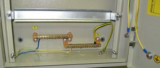
To create good and reliable grounding in a private home, there is a very simple and easy-to-implement solution that guarantees results for a hundred years. This is the installation of house grounding using a ready-made, quickly assembled ZANDZ grounding kit (pr. Russia), designed specifically for this application.
Advantages
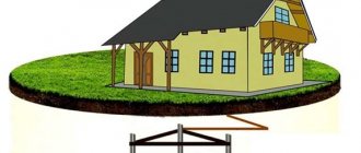
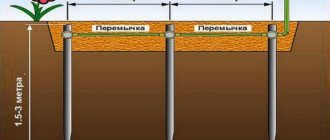
The main element of any grounding device is the ground electrode, which is a metal structure mounted in the ground. The ZANDZ grounding electrode, obtained from the “Grounding in a private house” kit, is a single prefabricated deep grounding electrode, consisting of four 1.5-meter steel pins coated with a layer of electrical copper.
The advantages of this design and the materials used:
- Service life up to 100 years
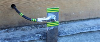
- Easy installation by one person without special tools. To build a ground electrode of the required length, 1.5-meter pins are buried into the ground one after another using a hand-held impact tool ( sledgehammer ). A bolt clamp is used to connect the conductor to the electrical panel.
- The minimum area occupied by the ground electrode allows it to be installed in the basements of houses, or close to walls in the form of just one point. Compactness minimizes required excavation work.
- No welding required*
- The quality of grounding does not depend on the weather and time of year
* The connection of elements of grounding devices NOT made of ferrous metals is permitted by technical circular 11/2006 of the RosElectroMontazh association (link to document)
The main purpose of this element
In any electrical device, grounding plays an important role, and its help when installing a home is invaluable, as a person protects himself from:
- Accidental electric shock, which can occur when accidentally touching an electrical appliance whose wiring is not sealed;
- Some modern devices will not work if there is no grounding in the house; this is also important to consider;
- Purchasing a kit will allow you to properly operate the gas installation;
- Excellent protection against electric lightning.
If the insulation of the electrical wiring is broken, the current will begin to close on the metal body of the product. If such a situation occurs, the electrical appliance will begin to have problems with its functioning, which can lead to breakdown. A person can immediately forget about safe operation, since the risk of electric shock increases significantly.
However, such a situation is possible if there is no grounding; when there is grounding, the electric current will be evenly distributed, which will reduce the likelihood of injury. But, in any case, it is not recommended to operate such a device; it is better to connect the broken wires with a heat pipe.
This describes only one example of using a set of thousands. With properly organized grounding, an electrical circuit will be created that will have a resistance several times less than the human body can withstand. The current passing through the body will not have any effect on it, and the entire dangerous charge will “hit” the ground.
The main part of any kit is the grounding loop, which is presented in the form of metal conductors and special rods buried in the ground (often called grounding electrodes).
The electrical cable located inside is made of three cores: phase, neutral and ground. This is the most common standard and shows high results. The protective grounding wiring is fixed together with the circuit of the electrical product.
To ensure the greatest safety during a thunderstorm, special elements are used - arresters. They are designed to work with high current and voltage parameters, without negative consequences for other devices.
Restrictions on use
ZZ-6 is designed for installation in
soft clay soils (for example, loams). It is difficult, but acceptable, to install in dense clay soils (for example, heavy clay).
Installation in hard sandy and rocky soils is not possible. This limitation is due to the low impact energy of the hand tool (sledgehammer) used during installation.
To install a grounding switch in dense or hard soil, we recommend using modular grounding kits (on a separate page).
Packaging information
Article: ZZ-6
The kit is packaged in a strong cardboard box with a plastic carrying handle. Inside the box are parts of the grounding kit, as well as an installation manual and a pair of proprietary stickers for placement on the electrical panel door or other flat surface at the buyer's discretion.
| ZZ-6 | |
| Weight: | 12 kg |
| Length: | 155 cm |
| Width: | 25 cm |
| Height: | 7 cm |
Price - 12,000.00 RUR.
Buy Order installation
Dealers in Russia and CIS countries
You can purchase ready-made ZANDZ grounding kits, as well as individual components, not only in our online store, but also from a friendly trading company that has its own warehouse in the city where we operate.
Purchasing from a local dealer will save you time and money on delivery of goods from the central warehouse in Moscow. If the dealer has a sales floor, you can get acquainted with the grounding kits and components “live”.
List of dealers in Russia and the CIS
Grounding kit ZZ-6
(pr. Russia) contains all the necessary parts for installing the ground electrode, which are easily mated to each other.
Copper-plated coupling-free grounding pin (D17 mm / L1.5 m) 4 pieces
The basis of the kit is a 1.5 m long pin with a thick copper coating (for maximum service life). One of the ends is narrowed; a blind hole is made at the other end to connect the pins to each other (to increase the total length of the electrode).
During installation, the connection is automatically pressed, forming a very reliable electrical and mechanical contact.
To install couplingless pins, it is necessary to use a dowel that transmits the impact force to the center of the pin.
| ZZ-6-1 | |
| Pin diameter: | 17 mm |
| Length: | 1.51 m |
| Weight: | 2.75 kg |
| Thread diameter: | 16 mm |
Detailed information about production technology and coating testing is presented on a separate page.
Dowel for installation with a sledgehammer 1 piece
The hardened steel dowel is designed to transfer the impact energy of the tool (sledgehammer) to the center of the pin. During installation it is located in the groove part of the pin.
| ZZ-6-4 | |
| Weight: | 0.12 kg |
| Length: | 70 m |
| Diameter: | 16 mm |
Clamp for connecting conductor 1 piece
Profiled stainless steel clamp with M10 bolts. Allows you to connect the rod to a grounding conductor - a round wire or strip (up to 40 mm wide).
It is possible to safely use steel and galvanized conductors - for this purpose, there is a gasket inside the clamp that prevents the formation of an electrochemical bond between steel/zinc and copper.
To prevent self-unscrewing of bolt-nut threaded connections, spring washers (Grover washers/Grover washers) are installed between the clamp surface and the nut.
| ZZ-6-5 | |
| Weight: | 0.358 kg |
| Length: | 80 mm |
| Width: | 80 mm |
| Height: | 30 mm |
Equipment
ZANDZ ready-made modular grounding kits are a universal solution for typical cases. If necessary, the kit can include any required number of components (individual kits are available upon request).
| ZZ-000-015 | ZZ-000-030 | |
| Copper-plated threaded grounding pin (D14; 1.5 m), pcs. | 10 | 20 |
| Threaded coupling, pcs. | 10 | 20 |
| Starting tip, pcs. | 3 | 3 |
| Guide head for attachment to a jackhammer, pcs. | 2 | 3 |
| Clamp for connecting conductor, pcs. | 3 | 3 |
| Conductive grease, pcs. | 1 | 1 |
| Waterproofing tape, pcs. | 1 | 1 |
| Jackhammer attachment (SDS max), pcs. | 1 | 1 |
| ZZ-000-045 | ZZ-000-424 | ZZ-000-636 | |
| Copper-plated threaded grounding pin (D14; 1.5 m), pcs. | 30 | 16 | 24 |
| Threaded coupling, pcs. | 16 | 16 | 24 |
| Starting tip, pcs. | 15 | 4 | 6 |
| Guide head for attachment to a jackhammer, pcs. | 5 | 3 | 3 |
| Clamp for connecting conductor, pcs. | 15 | 4 | 6 |
| Conductive grease, pcs. | 1 | 1 | 1 |
| Waterproofing tape, pcs. | 5 | 2 | 2 |
| Jackhammer attachment (SDS max), pcs. | 1 | 1 | 1 |
Before installation
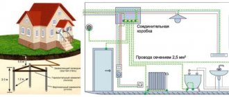
When placing a grounding electrode INSIDE a house, the installation location is determined based on considerations of the mechanical protection of the grounding conductor from this grounding electrode to the electrical panel at the place where it is installed, the dryness of the room, and the convenience of installing the pins in the ground. The best location would be a position within a radius of 0.5 meters from the shield to achieve the shortest conductor length. The maximum distance from the shield is not limited.
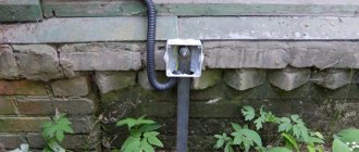
When placing a grounding conductor OUTSIDE the house, you need to take into account that the grounding conductor must be laid to a depth of 0.5 - 0.7 meters in a pre-dug channel. This measure is mandatory and necessary to protect the conductor from mechanical damage during operation and to minimize weather / seasonal influences, which increases its service life. The ground electrode is mounted in the same channel. The grounding conductor is inserted through the wall inside a steel pipe.
Necessary materials:
- kit “Grounding in a private house” ZZ-6
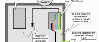
- copper wire/cable with a cross section of 16 or 25 mm² of the required length. When laying in the ground, a conductor with a minimum cross-section of 25 mm² is required.
- silicone sealant
Required tools:
- percussion hand tool weighing 300 - 1500 g: sledgehammer or heavy hammer
- two wrenches or two pliers (to tighten the clamp bolts)
The procedure for installing the ground electrode
Stainless steel sealing sleeves are mounted on pins for easy transportation. The bushings must be removed before installation.
Performed operations:
- Insert a dowel into the pin hole.
- Drive the pin into the ground, striking the pin with the tool.
- Remove the dowel and place the bushing on the mounted pin (with the wide part down).
- Insert the next pin with the pointed part into the mounted pin with the bushing on. The connection is self-pressed during installation.
- Repeat steps 1-4 until the ground electrode reaches the desired depth. The last pin must be left 20 cm above the ground. The sleeve does not fit onto the last recessed pin.
- Install the clamp for connecting the grounding conductor and, having connected the conductor itself, tighten the clamp bolts with maximum force.
- Fill the hole in the pin generously with sealant to prevent moisture from entering.
An example of grounding installation in a private house
See also a full description of the calculations and a video recording of the grounding installation on a separate page.
Requirements for the quality of grounding at home
If you do not plan to connect lightning protection and gas equipment to grounding:
- in ordinary clay soil, high-quality local (repeated) grounding should have a recommended resistance of no more than 30 Ohms (at a linear voltage of 220 V from a single-phase current source or at a linear voltage of 380 V from a three-phase current source)
- in sandy soil, high-quality local (repeated) grounding should have a recommended resistance of no more than 150 Ohms (with a linear voltage of 220 V of a single-phase current source or with a linear voltage of 380 V of a three-phase current source)
What is popular now and the main recommendations
Today, three grounding options are more common, each of which differs in technical parameters and capabilities:
- TN;
- TT;
- IT.
If a person plans to use the set only in a country house, then it is better for him to pay attention to the first option, which is also divided into several groups and can be: TN-C, TN-S, TN-CS, what you choose is decided based on your goals.
Requirements for grounding quality (special cases)
If grounding will be used together with lightning rods:
- in ordinary clay soil, the grounding resistance should be no more than 10 Ohms (RD 34.21.122-87, clause.

- in sandy soil, the grounding resistance should be no more than 40 Ohms (RD 34.21.122-87, clause 8; for soils with electrical resistivity more than 500 Ohm*m)
In this case, the ground electrode must contain at least 3 vertical electrodes, spaced apart from each other at a distance of at least two immersion depths of the electrodes (RD 34.21.122-87, clause 2.2.d).
Read more about this application on the separate page “Lightning protection and grounding”.
If grounding will be used to connect a gas boiler / gas pipeline:
- in ordinary clay soil its resistance should be no more than 10 Ohms (PUE 1.7.103; for all repeated groundings).
- in sandy soil its resistance should be no more than 50 Ohms (PUE 1.7.103; for all repeated groundings; for soils with a resistance of more than 500 Ohm*m).
It is recommended to make the grounding electrode in the form of one electrode (point grounding). Read more about this application on the separate page “Grounding a gas boiler / gas pipeline”.
Soil resistance indicators
The magnitude of the soil resistance shows how well the current will flow in it. The value of this indicator largely depends on the composition of the soil, the fraction and density of particles adjacent to each other.
Soil resistance table
| Soil type | Resistance, Ohm/m |
| Permanently frozen ground | 500-50000 |
| Dry sand | 400-4000 |
| Wet sand | 10-400 |
| Loam | 10-150 |
| Clay | 20-60 |
Choosing a grounding system (TT / TN) for a private house
In 2007, the Department of State Energy Supervision sent a letter (No. 10-04/481) to the heads of MTU and the heads of UTEN Rostechnadzor, stating that in order to clarify and supplement the requirements of regulatory and technical documents in the electric power industry and ensure safety measures during the operation of electrical installations, ( approved / agreed upon) technical circulars (TC), which are recommended to be used for guidance and application when checking design documentation and commissioning new and reconstructed electrical installations:
- No. 6/2004 dated February 16, 2004 “On the implementation of the main potential equalization system at the entrance to buildings”;
- No. 7/2004 dated 04/02/2004 “On the installation of electrical wiring behind suspended ceilings and in partitions”;
- No. 10/2006 dated 02/01/2006 “On temporary power supply schemes for construction sites”;
- No. 11/2006 dated October 16, 2006 “On grounding electrodes and grounding conductors”;
In the commentary to TC No. 11/2006 “On grounding electrodes and grounding conductors” (from the developer of this TC: Mr. Shalygin A.A., head of the ICC of the Moscow Institute of Energy Safety and Energy Saving) it is stated:
In accordance with the instructions of clause 1.7.59 of the PUE of the seventh edition: “Power supply of electrical installations with voltage up to 1 kV from a source with a solidly grounded neutral and with grounding of open conductive parts using a ground electrode not connected to the neutral (TT system) is allowed only in those cases when electrical safety conditions in the TN system cannot be ensured. To protect against indirect contact in such electrical installations, the power must be automatically turned off with the mandatory use of an RCD...”
An example of an electrical installation where it is impossible, within the limits of reasonable technical solutions, to meet the electrical safety requirements in the TN system is individual residential buildings, which, according to local conditions, must be connected to a 0.4 kV overhead line made with bare wires (OHL). The fact is that the neutral conductor of an overhead line cannot be considered as a PEN conductor by definition. Under these conditions, before replacing bare overhead line wires with self-supporting insulated wires, the use of a TT protective grounding system is justified.
At the input to such installations, for automatic power off, an RCD with a rated differential operating current of 300 or 500 mA is usually installed. The resistance of the grounding device is chosen to be about 30 Ohms, and for soils with high volumetric resistance up to 300 Ohms. With such parameters of the grounding device, reliable operation of the RCD is ensured, and short-circuit currents are insignificant.
Later, in 2012, TC No. 31/2012 “On re-grounding and automatic power outage at the input of individual construction projects” was published. Its text (with some abbreviations):
Individual construction projects, as a rule, receive power via a branch from overhead power lines with voltages up to 1 kV.
For new construction projects and during reconstruction, in accordance with the instructions of Chapter 2.4 of the PUE of the seventh edition, overhead lines are made using self-supporting insulated wires and are designated as VLI.
Most existing individual construction projects receive power from overhead lines using uninsulated overhead line wires, made according to the standards of Chapter 2.4 of the PUE of the sixth and earlier editions.
... The purpose of this circular is to issue specific recommendations for ensuring protection against indirect contact in electrical installations receiving power from overhead lines and overhead lines up to 1 kV. When choosing measures to protect against indirect contact in electrical installations receiving power from overhead lines and overhead lines up to 1 kV, you must be guided by the following:
- Since for objects receiving power from overhead lines with voltages up to 1 kV, it is impossible for most consumers to meet the requirements for automatic shutdown due to low multiples of short-circuit currents, the installation of a residual current device (RCD) with a differential operating current of up to 300 mA at the input is mandatory . Note. The installation of an RCD with a differential operating current of up to 300 mA at the input is also mandatory from the point of view of ensuring fire safety.
- When powered from a VLI, the consumer's re-grounding resistance is selected from the condition of ensuring reliable operation of the RCD in the event of insulation damage (single-phase ground fault) when the PEN conductor of the branch from the VLI is disconnected. The resistance is calculated based on the reliable operation current of the RCD, equal to five times the size of this current, but should not exceed 30 Ohms. If the soil resistivity is more than 300 Ohm*m, the resistance can be increased to 150 Ohm.
- When powered from an overhead line, in accordance with the instructions of clause 1.7.59 of the seventh edition of the PUE and clause 531.2.3 of IEC 60364-5-53 (the Russian analogue of GOST R 50571-5-53 is being prepared for release), the TT protective grounding system should be used . The re-grounding parameters are selected in accordance with the instructions in paragraph 2 of this technical circular.
- The use of the TT system is considered as a temporary (forced) measure. After the reconstruction of overhead lines and the transition to overhead lines in electrical installations, you should switch to the TN protective grounding system; for this, a jumper should be installed in the input device between the N and PE buses.
Recommended actions when replacing TN-C
Most residential buildings are equipped with this option. Due to the fact that the buildings have a two-wire electrical supply system, the use of TN-C is a suitable solution. Because the system uses only one conductor, which is capable of solving two problems:
- working, for the proper functioning of electrical products and devices;
- protective, which ensures the safety of devices.
Such a system meets basic safety standards and protects the entire electrical circuit, but it is not able to preserve the powered electrical units, which can lead to their failure when a high load occurs. It is also important to understand that in rainy weather, such a connection will lead to voltage surges, even if a protective shutdown is applied. Unfortunately, there are even cases of death due to this flaw.
Therefore, when constructing new buildings, using such a solution is highly not recommended. I use such a system only where it was originally installed, but if a person wants to change it, this can be easily done. Most often, people use TN-CS for these purposes, so a PEN cable is installed at the input, which is later divided into PE and N. Thanks to this solution, in the event of an emergency, the N wire is disconnected from the general network, which allows you to keep all household appliances intact and will save a person from additional costs.
