Requirements for grounding electrical installations up to 1000V are given in section 1.7 of PUE 7 (Rules for electrical installations in the seventh edition). Section 1.7 “Grounding and protective electrical safety measures” contains general requirements for grounding electrical installations and protecting people and animals from electric shock both during normal operation of the electrical installation and in the event of insulation damage.
Let us highlight the provisions of this section that relate to the grounding of electrical installations up to 1000 V.
Electrical installations up to 1000 V with regard to electrical safety measures are divided into:
- electrical installations with voltage up to 1 kV in networks with a solidly grounded neutral;
- electrical installations with voltage up to 1 kV in networks with an insulated neutral.
Paragraphs 1.7.120 to 1.7.177
Clauses 1.7.1 to 1.7.79 Clauses 1.7.80 to 1.7.119
APPROVED by the Ministry of Energy of the Russian Federation
Order of July 8, 2002 No. 204
Enters into force on January 1, 2003.
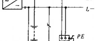
1.7.120. If the building has several separate inputs, the main grounding bus must be made for each input device. If there are built-in transformer substations, the main grounding bus must be installed near each of them. These buses must be connected by a potential equalization conductor, the cross-section of which must be at least half the PE
(
PEN
) - the conductor of that line among the substations extending from the switchboards of low voltage, which has the largest cross-section. Third-party conductive parts may be used to connect multiple main ground bars if they meet the electrical continuity and conductivity requirements of 1.7.122.
Protective conductors ( PE
- conductors)
1.7.121. As RE
-conductors in electrical installations with voltage up to 1
kV
can be used:
1) specially provided conductors:
cores of multi-core cables;
insulated or non-insulated wires in a common sheath with phase wires;
permanently laid insulated or non-insulated conductors;
2) open conductive parts of electrical installations:
aluminum cable sheaths
steel pipes for electrical wiring;
metal shells and supporting structures of busbars and complete prefabricated devices.
Metal boxes and trays of electrical wiring can be used as protective conductors, provided that the design of the boxes and trays provides for such use, as indicated in the manufacturer's documentation, and their location excludes the possibility of mechanical damage;
3) some third party conductive parts:
metal building structures of buildings and structures (trusses, columns, etc.);
reinforcement of reinforced concrete building structures, subject to the requirements of 1.7.122;
metal structures for industrial purposes (crane rails, galleries, platforms, elevator shafts, lifts, elevators, channel frames, etc.).
1.7.122. Use of exposed and third-party conductive parts as PE
- conductors are allowed if they meet the requirements of this chapter for conductivity and continuity of the electrical circuit.
Third party conductive parts can be used as PE
- conductors, if they, in addition, simultaneously meet the following requirements:
1) the continuity of the electrical circuit is ensured either by their design or by appropriate connections protected from mechanical, chemical and other damage;
2) their dismantling is impossible unless measures are taken to maintain the continuity of the circuit and its conductivity.
1.7.123. The following are not allowed to be used as PE conductors:
metal shells of insulating tubes and tubular wires, supporting cables for cable wiring, metal hoses, as well as lead sheaths of wires and cables;
gas supply pipelines and other pipelines of flammable and explosive substances and mixtures, sewerage and central heating pipes;
water pipes with insulating inserts.
.7.124. Neutral protective conductors of circuits are not allowed to be used as neutral protective conductors of electrical equipment powered by other circuits, and also to use open conductive parts of electrical equipment as neutral protective conductors for other electrical equipment, with the exception of shells and supporting structures of busbars and complete factory-made devices that provide the possibility connecting protective conductors to them in the right place.
1.7.125. The use of specially designed protective conductors for other purposes is not permitted.
1.7.126. The smallest cross-sectional areas of protective conductors must comply with table. 1.7.5.
The cross-sectional areas are given for the case when the protective conductors are made of the same material as the phase conductors. The cross-sections of protective conductors made of other materials must be equivalent in conductivity to those given.
Table 1.7.5
Design and types of circuits
The task and features of grounding transformers.
The standard ground loop is made not only in the form of a triangle, which is optimal for most conditions; it can be in the shape of a line, a rectangle, an angle, or even an arc (oval). When considering each of these structures from the point of view of their resistance, the following should be noted:
- The basis of the design is pins or rods driven into the ground;
- They are connected to each other by metal strips cut to length (the so-called “metal bond”);
- A copper busbar is welded to one of the pins or to a strip of metal, laid in a separate groove, as shown in the figure below.
Laying the busbar to the short circuit structure
The choice of a triangle as the main type of ground electrode is explained by the fact that in this case it is possible to obtain the maximum dispersion zone with a small occupied area. The material costs for such a structure are minimal, and the resistance to spreading in the ground, if properly constructed, complies with the standards.
The distance between the pins of a triangular contour is usually chosen equal to the length, and the maximum distance from one to the other can be twice as large. So, if the pins are buried 250 centimeters into the ground, it can reach 5 meters. Only if these conditions are met is it possible to obtain optimal characteristics of a structure buried in the ground.
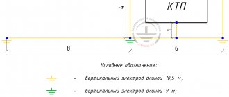
The linear contour is a chain of pins driven into the ground at a certain pitch of approximately 5-10 meters (see the figure below).
Linear distributed circuit
In some cases, depending on terrain conditions, the structure is constructed in the form of a semicircle; in this case, the pins are located at the same distance from one another. In such a distributed device, the resistance should be minimal precisely at the points of contact of the rods with the ground. To achieve the required R3 value, as many pins as possible are hammered in.
All other types of structures are modifications of the ground electrodes described above, and the requirements for drainage resistance are derived from those already considered.
Smallest cross-sections of protective conductors
| Section of phase conductors, mm2 | Minimum cross-section of protective conductors, mm2 |
| S ≤ 16 16 < S ≤ 35 S > 35 | S 16 S /2 |
It is allowed, if necessary, to take the cross-section of the protective conductor less than required if it is calculated according to the formula (only for shutdown time ≤ 5 s
):
where S
— cross-sectional area of the protective conductor,
mm2
;
I
- short circuit current, providing the time to disconnect the damaged circuit by the protective device in accordance with Table.
1.7.1 and 1.7.2 or in a time of no more than 5 s
in accordance with 1.7.79,
A
;
t
— response time of the protective device,
s
;
k
— coefficient, the value of which depends on the material of the protective conductor, its insulation, initial and final temperatures.
The values of k
for protective conductors under various conditions are given in table. 1.7.6-1.7.9.
If the calculation results in a cross section different from that given in table. 1.7.5, then you should select the nearest larger value, and when obtaining a non-standard cross-section, use conductors of the nearest larger standard cross-section.
The maximum temperature values when determining the cross-section of the protective conductor should not exceed the maximum permissible heating temperatures of the conductors during a short circuit
in accordance with Ch. 1.4, and for electrical installations in explosive areas must comply with GOST 22782.0 “Explosion-proof electrical equipment. General technical requirements and test methods".
1.7.127. In all cases, the cross-section of copper protective conductors that are not part of the cable or laid not in a common shell (pipe, box, on the same tray) with phase conductors must be no less than:
2,5 mm2
— with mechanical protection;
4 mm2
- in the absence of mechanical protection.
The cross-section of separately laid protective aluminum conductors must be at least 16 mm2
.
1.7.128. In the TN
To meet the requirements of 1.7.88, it is recommended that neutral protective conductors be laid together or in close proximity to phase conductors.
Table 1.7.6
How to ground electrical equipment?
From time to time you can hear the demand to make the grounding installation visible.
Such conditions are expressed not only by customers who are far from electricians, but also by members of inspection authorities. The requirement is not correct in this formulation. So let's discuss a few details:
- The entire installation cannot be visible. The grounding circuit must be dug into the ground.
- The PUE does not have requirements for a visible ground loop.
- But visible grounding of electrical equipment is indeed required.
Let's turn to PUE 1.7.116. This talks about the need to disconnect the grounding conductor to measure the resistance.
PTEEP clause 2.7.8, among other things, speaks of the need for a visual inspection of the visible part.
The value of the k coefficient for a protective conductor included in a multi-core cable
| Parameter | Insulation material | ||
| Polyvinyl chloride ( PVC ) | Cross-linked polyethylene, ethylene propylene rubber | Butyl rubber | |
| Initial temperature, °C | 70 | 90 | 85 |
| Final temperature, °C | 160 | 250 | 220 |
| k conductor: copper aluminum | 115 76 | 143 94 | 134 89 |
Table 1.7.8
How to ground electrical equipment?
From time to time you can hear the demand to make the grounding installation visible.
Such conditions are expressed not only by customers who are far from electricians, but also by members of inspection authorities. The requirement is not correct in this formulation. So let's discuss a few details:
- The entire installation cannot be visible. The grounding circuit must be dug into the ground.
- The PUE does not have requirements for a visible ground loop.
- But visible grounding of electrical equipment is indeed required.
Let's turn to PUE 1.7.116. This talks about the need to disconnect the grounding conductor to measure the resistance.
PTEEP clause 2.7.8, among other things, speaks of the need for a visual inspection of the visible part.
Combined neutral protective and neutral working conductors (PEN conductors)
1.7.131. In multiphase circuits in a TN
for permanently laid cables, the conductors of which have a cross-sectional area of at least 10
mm2
for copper or 16
mm2
for aluminum, the functions of the neutral protective (
PE
) and neutral working (
N
) conductors can be combined in one conductor (
PEN
conductor).
1.7.132. It is not allowed to combine the functions of the neutral protective and neutral working conductors in single-phase and direct current circuits. A separate third conductor must be provided as a neutral protective conductor in such circuits. This requirement does not apply to branches from overhead lines
voltage up to 1
kV
to single-phase electricity consumers.
1.7.133. It is not allowed to use third party conductive parts as the only PEN
- conductor.
This requirement does not preclude the use of exposed and third-party conductive parts as an additional PEN
- conductor when connecting them to the potential equalization system.
1.7.134. Specially provided PEN
-conductors must comply with the requirements of 1.7.126 for the cross-section of protective conductors, as well as the requirements of Ch. 2.1 to the neutral working conductor.
PEN insulation
-conductors must be equivalent to the insulation of phase conductors.
It is not necessary to insulate the PEN
of the busbars of low-voltage complete devices.
1.7.135. When the neutral working and neutral protective conductors are separated starting from any point in the electrical installation, it is not allowed to combine them beyond this point along the distribution of energy. At the point where the PEN
- conductor for the neutral protective and neutral working conductors, it is necessary to provide separate clamps or busbars for the conductors, interconnected.
The PEN
conductor of the supply line must be connected to the terminal or bus of the neutral protective
PE
conductor.
Potential equalization system conductors
1.7.136. Open and third-party conductive parts specified in 1.7.121, or specially laid conductors, or a combination thereof, can be used as conductors of the potential equalization system.
1.7.137. The cross-section of the conductors of the main potential equalization system must be at least half the largest cross-section of the protective conductor of the electrical installation, if the cross-section of the potential equalization conductor does not exceed 25 mm2
for copper or equivalent from other materials.
The use of conductors of larger cross-sections is, as a rule, not required. In any case, the cross-section of the conductors of the main potential equalization system must be no less than: copper - 6 mm2
, aluminum - 16
mm2
, steel - 50
mm2
.
1.7.138. The cross-section of the conductors of the additional potential equalization system must be no less than:
when connecting two open conductive parts - the cross-section of the smaller of the protective conductors connected to these parts;
when connecting an open conductive part and a third-party conductive part - half the cross-section of the protective conductor connected to the open conductive part.
The cross-sections of additional potential equalization conductors that are not part of the cable must comply with the requirements of 1.7.127.
Basic terms
clause 1.7.5. Solidly grounded neutral - the neutral of a transformer or generator connected directly to the grounding device. The output of a single-phase alternating current source or the pole of a direct current source in two-wire networks, as well as the midpoint in three-wire DC networks, can also be solidly grounded.
clause 1.7.6. Isolated neutral - the neutral of a transformer or generator, not connected to a grounding device or connected to it through a high resistance of signaling, measuring, protection and other similar devices.
1.7.15. Ground electrode - a conductive part or a set of interconnected conductive parts that are in electrical contact with the ground directly or through an intermediate conductive medium.
1.7.16. An artificial grounding conductor is a grounding conductor specially made for grounding purposes.
1.7.17. Natural grounding - a third-party conductive part that is in electrical contact with the ground directly or through an intermediate conducting medium, used for grounding purposes.
1.7.18. Grounding conductor is a conductor connecting the grounded part (point) to the ground electrode.
1.7.19. Grounding device - a combination of grounding conductors and grounding conductors.
Portable electrical receivers
1.7.147. The Rules include portable electrical receivers that can be in the hands of a person during their operation (hand-held power tools, portable household electrical appliances, portable radio-electronic equipment, etc.).
1.7.148. Portable AC power receivers should be powered from a mains voltage not exceeding 380/220 V
.
Depending on the category of the room in terms of the level of danger of electric shock to people (see Chapter 1.1), automatic power off, protective electrical separation of circuits, ultra-low voltage, and double insulation can be used to protect against indirect contact in circuits feeding portable electrical receivers.
1.7.149. When using automatic power off, the metal housings of portable power receivers, with the exception of power receivers with double insulation, must be connected to the neutral protective conductor in the TN
or grounded in the
IT
, for which a special protective (
PE
) conductor must be provided, located in the same shell with the phase conductors (the third core of the cable or wire is for single-phase and direct current electrical receivers, the fourth or fifth core is for three-phase current electrical receivers), connected to the body of the electrical receiver and to the protective contact of the plug connector.
The PE
conductor must be copper, flexible, its cross-section must be equal to the cross-section of the phase conductors.
The use of a neutral working ( N
) conductor for this purpose, including one located in a common shell with phase conductors, is not permitted.
1.7.150. It is allowed to use stationary and separate portable protective conductors and potential equalization conductors for portable electrical receivers in testing laboratories and experimental installations, the movement of which is not intended during their operation. In this case, stationary conductors must meet the requirements of 1.7.121-1.7.130, and portable conductors must be copper, flexible and have a cross-section no less than that of phase conductors. When laying such conductors not as part of a cable common with phase conductors, their cross-sections must be no less than those specified in 1.7.127.
1.7.151. For additional protection against direct contact and indirect contact, socket outlets with a rated current of no more than 20 A
outdoor installation, as well as indoor installation, but to which portable electrical receivers can be connected, used outside buildings or in premises with increased danger and especially dangerous ones, must be protected by residual current devices with a rated residual current of no more than 30
mA
.
It is allowed to use hand-held power tools equipped with RCD
plugs.
When using protective electrical separation of circuits in cramped rooms with a conductive floor, walls and ceiling, as well as if there are requirements in the relevant chapters of the Electrical Code in other rooms with special danger, each outlet must be powered from an individual isolation transformer or from its separate winding.
When using ultra-low voltage, power supply of portable electrical receivers with voltages up to 50 V
must be carried out from a safety isolating transformer.
1.7.152. To connect portable electrical receivers to the power supply network, plug connectors should be used that meet the requirements of 1.7.146.
In plug connectors of portable power receivers, extension wires and cables, the conductor on the power source side must be connected to the socket, and on the power receiver side - to the plug.
.7.153. RCD
Protection of socket circuits is recommended to be placed in distribution (group, apartment) panels.
It is allowed to use RCD
sockets.
1.7.154. The protective conductors of portable wires and cables must be marked with yellow-green stripes.
Helpful information
Grounding lamps, like supports, is one of the stages of installing outdoor lighting. Installation of grounding is the most important and mandatory stage in the installation of an external lighting system. The installation of this system itself has several stages.
Note! In order to properly ground the lamps to the support structure, it is necessary to strictly adhere to the rules and regulations that are prescribed in the PUE. This will avoid breakdown in the insulation of the power cable and prevent electrical injury.
Outdoor lighting installation
According to established instructions developed for the arrangement of grounding networks, all metal supports, without exception, that are elements of an external lighting system are subject to mandatory grounding. The principle of grounding is that if there is a violation of the insulation of the electrical wiring of the lamps, the electric current begins to flow into the ground. As a result, a voltage distribution will occur in the area where the electric current spreads, which will become harmless to humans. The voltage distribution depends on the resistivity of the soil, as well as the placement of ground electrodes on the supports of the street lighting system.
Mobile electrical installations
1.7.155. The requirements for mobile electrical installations do not apply to: ship electrical installations;
electrical equipment located on moving parts of machines, machines and mechanisms;
electrified transport;
RVs.
For testing laboratories, the requirements of other relevant regulations must also be met.
1.7.156. An autonomous mobile power supply source is a source that allows consumers to be powered independently of stationary sources of electricity (power system).
1.7.157. Mobile electrical installations can be powered from stationary or autonomous mobile power sources.
Power supply from a stationary electrical network should, as a rule, be supplied from a source with a solidly grounded neutral using TN-S
or
TN-CS
.
Combining the functions of the neutral protective conductor PE
and the neutral working conductor N in one common conductor
PEN
inside a mobile electrical installation is not allowed.
The separation of the PEN
- supply line conductor into
PE
- and
N
- conductors must be performed at the point where the installation is connected to the power source.
When powered from an autonomous mobile source, its neutral, as a rule, must be isolated.
1.7.158. When powering stationary electrical receivers from autonomous mobile power sources, the neutral mode of the power source and protection measures must correspond to the neutral mode and protection measures taken for stationary electrical receivers.
1.7.159. In the case of powering a mobile electrical installation from a stationary power source, for protection against indirect contact, the power must be automatically turned off in accordance with 1.7.79 using an overcurrent protection device. In this case, the shutdown time given in table. 1.7.1, must be halved or, in addition to the overcurrent protection device, a residual current device must be used that responds to differential current.
In special electrical installations, the use of RCDs
, responding to the potential of the body relative to the ground.
When using RCD
, responding to the chassis potential relative to the ground, the setting for the shutdown voltage value should be equal to 25
V
with a shutdown time of no more than 5
s
.
1.7.160. At the point of connection of the mobile electrical installation to the power source, an overcurrent protection device and an RCD
, responding to differential current, the rated disconnecting differential current of which should be 1-2 steps greater than the corresponding
RCD
installed at the entrance to the mobile electrical installation
If necessary, protective electrical separation of circuits can be used at the entrance to a mobile electrical installation in accordance with 1.7.85. In this case, the isolation transformer, as well as the input protective device, must be placed in an insulating shell.
The device for connecting the power input to a mobile electrical installation must have double insulation.
1.7.161. When applying automatic power shutdown in an IT
To protect against indirect contact, the following must be done:
protective earthing combined with continuous insulation monitoring acting on the signal;
automatic power off, providing a shutdown time in the event of a two-phase short circuit to open conductive parts in accordance with table. 1.7.10.
Table 1.7.10
Electrical installations of animal premises
1.7.170. Electrical installations in livestock buildings should, as a rule, be powered from a 380/220 V
alternating current.
1.7.171. To protect people and animals from indirect contact, automatic power off must be performed using the TN-CS
.
The division of the PEN
conductor into neutral protective (
PE
) and neutral working (
N
) conductors should be done at the input panel.
TN-S
system must be used , and the neutral working conductor must have insulation equivalent to the insulation of the phase conductors along its entire length.
The time of protective automatic power off in premises for keeping animals, as well as in premises connected to them using third-party conductive parts, must comply with table. 1.7.11.
Table 1.7.11
Preface
DEVELOPED taking into account the requirements of state standards, building codes and regulations, recommendations of scientific and technical councils for reviewing draft chapters. Draft chapters were reviewed by the working groups of the Coordination Council for the revision of the EMP
PREPARED BY Teploelektroproekt Institute OJSC
agreed in accordance with the established procedure with the Gosstroy of Russia, Gosgortekhnadzor of Russia, RAO UES of Russia (JSC VNIIE)
APPROVED by the Ministry of Energy of Russia, order dated June 20, 2003 N 242