Today it is difficult to imagine your life without electricity, but in order to use all the benefits of electric current during the installation of electrical panels, transformers and other electrical installations, you need to adhere to the basics of electrical safety and know how to protect against voltage.
Methods of protection: general characteristics
Today there are several methods of protection against electric current, and they depend on the electrical installation.
Thus, the following protective measures can be distinguished:
- grounding;
- zeroing;
- shutdown;
- network separation;
- insulation;
- alignment;
- use low voltage.
These types of protection can be used either individually or in combination with each other. For example, in electrical installations with a voltage of 1000 V, grounding can be combined with insulation or with protective disconnection. If a transformer or other installation uses voltages up to 1000 V and above 1000 V, then it is recommended to apply winding insulation between these two voltage types. To do this, you can use special adapters that allow you to control differences. Adapters can be installed on each phase responsible for supplying a lower voltage.
If the electrical installation has 1000 V and a solidly grounded neutral is used, then protection methods such as grounding or disconnection can be used. Protective shutdown can be used as a main method of protection or as an auxiliary one.
General informationThere are the following protection methods, used separately or in combination with each other: protective grounding, grounding, protective shutdown, electrical separation of networks of different voltages, use of low voltage, insulation of live parts, potential equalization.
In electrical installations (EI) with voltages up to 1000 V with an isolated neutral and in DC EIs with an isolated midpoint, protective grounding is used in combination with insulation monitoring or protective shutdown.
In these electrical installations, a network with a voltage of up to 1000 V, connected to a network with a voltage above 1000 V through a transformer, is protected from the appearance of high voltage in this network if the insulation between the low and high voltage windings is damaged by a breakdown fuse, which can be installed in each phase on the low voltage side transformer.
In electrical installations with voltages up to 1000 V with a solidly grounded neutral or a grounded midpoint, grounding or protective shutdown is used in DC power plants. In these electrical installations, grounding the housings of electrical receivers without grounding them is prohibited.
Protective shutdown is used as a primary or additional method of protection if safety cannot be ensured by using protective grounding or grounding or their use causes difficulties
If it is impossible to use protective grounding. After grounding or protective shutdown, servicing of the power plant from insulating platforms is allowed.
Protective grounding
Grounding (Fig. 4.7) is the connection to the ground of non-current-carrying metal parts of electrical equipment through metal parts laid in the ground and called grounding conductors, and parts laid between grounding conductors and electrical equipment housings, called grounding conductors. Conductors and ground electrodes are usually made of low-carbon steel, colloquially called iron.
Grounding electrodes in the form of pins driven into the ground are called electrodes, and can be single or group. The ground electrode has characteristics determined by the flow of current through it into the ground. The characteristics of the ground electrode include:
- voltage on the ground electrode;
- change in the potentials of points in the ground around the ground electrode depending on their distance from the ground electrode in the current spreading zone - type of potential curve;
- type of lines of equal potential - equipotential lines on the surface of the earth;
- resistance of the grounding device;
- touch and step tension.
In Fig. Figure 4.8 shows a diagram of a simple ground electrode in the form of a rod or pipe driven into the ground and a view of the potential curves and equipotential lines.
At a distance of less than 40 m between single grounding conductors in a group grounding conductor, their spreading zones overlap each other, and a single spreading zone of a group grounding conductor is obtained, which has its own potential curve.
Touch voltage
Touch voltage is the voltage on the body of electrical equipment with damaged insulation that can be touched by a person. This voltage depends on the state of the grounding, the distance between the person and the ground electrode, and the resistance of the base on which the person stands.
In Fig. 4.9, o shows the influence of the position of a person relative to the ground electrode with a single ground electrode on the magnitude of the touch voltage. Touch voltage is maximum in position 1
a person when he stands in the zero potential zone and touches grounded equipment;
equals zero at position 2,
when a person stands on a ground electrode or its projection onto the surface of the earth, in some intermediate position of the person the touch voltage has an intermediate value, which varies from O to U3.
In Fig. 4.9, b
The dependence of touch voltage on the position of a person with a group grounding is shown.
In this case, Upp
has the greatest value in position
1
of the person, when he is between the electrodes of the ground electrode, the lowest value in position
2,
when he stands on the ground electrode or its projection onto the surface of the earth, in any intermediate position Upp varies from 6 to the maximum value.
Step voltage
Step voltage occurs between the legs of a person standing on the ground due to the potential difference on the surface of the earth when a ground fault current spreads in the ground. There is no step voltage if a person stands either on a line of equal potential or outside the current spreading zone, i.e., at a distance of more than 20 m from the ground electrode.
In Fig. Figure 4.10 shows the dependence of the step voltage on the distance between a person and a single ground electrode. The step voltage is greatest in the position of 1 person, when he stands with one foot on the ground electrode. In the position of a person between the ground electrode and the zero potential zone, when the step is directed radially towards the ground electrode, the step voltage has an intermediate value.
Grounding is intended to eliminate the danger of electric shock to a person when touching non-current-carrying parts that are energized. This is achieved by reducing the touch and step voltages to safe limits due to the low resistance of the ground electrode. The scope of application of protective grounding is AC and DC networks with an isolated neutral of the voltage source or transformer.
AC electrical installations with voltages up to 42 V and DC electrical installations with voltages up to 110 V do not require protective grounding.
The resistance value of the grounding device is standardized by the “Electrical Installation Rules” (PUE). This value for electrical installations up to 1000 V with an isolated neutral should be no more than 4 ohms, and if the power of generators or transformers supplying the network, or their total power is no more than 100 kVA, then the resistance should be no more than 10 ohms.
For grounding, parts of existing structures can be used, which are called natural grounding electrodes:
- metal and reinforced concrete structures of buildings and structures in contact with the ground;
- metal pipelines laid in the ground, with the exception of pipelines of flammable liquids and gases;
- lead sheaths of cables laid in the ground;
- well casing pipes, etc.
The smallest sizes of artificial grounding electrodes:
- diameter of round electrodes, mm
- non-galvanized………………. 10
- galvanized……………….. 6
- cross-section of rectangular electrodes, mm^2 … 48
- thickness of rectangular electrodes, mm ... 4
- thickness of angle steel flanges, mm…….. 4
The following can be used as grounding and neutral (see below) conductors connecting equipment housings to grounding conductors:
- special conductors;
- metal structures of equipment and buildings;
- steel pipes for electrical wiring, aluminum cable sheaths;
- metal openly located pipelines for all purposes, with the exception of pipelines for flammable liquids and gases, sewage and central heating.
It is prohibited to use aluminum wires for laying in the ground, metal sheaths of tubular wires, support cables of cable wiring, metal hoses, armor and lead sheaths of wires and cables as grounding and neutral conductors.
The minimum dimensions of grounding and neutral conductors are shown in table. 4.2.
Table 4.2 MINIMUM SIZES OF GROUNDING AND ZERO CONDUCTORS
Conductors are connected to equipment bodies by welding or bolting, ensuring accessibility for inspection or alteration if contact deteriorates. Sequential connection of individual equipment enclosures to the grounding or grounding circuit is prohibited.
When installing grounding devices by the installation organization, control over the work is carried out by the customer. At the same time, works that will subsequently be hidden are accepted separately, and at this time, and not after, acts for hidden work are signed.
Installation organizations provide the customer with all documentation for grounding devices. A passport is issued for each device, which records all changes, results of inspections and measurements.
When checking the condition of the grounding, the visible part is periodically inspected, the circuit between the ground electrode and the grounded elements is checked, the resistance of the grounding device is measured, and the soil is selectively opened to inspect the elements located in the ground.
Measuring the resistance of the grounding device
Measurements are usually made using a special device - a grounding meter, for example, M-416, which works on the principle of an ammeter-voltmeter. When measuring the resistance of a complex circuit (Fig. 4.11, o), which has the largest diagonal D,
the current electrode
Et
is placed at a distance l1 = 2
D
from the edge of this circuit, and the potential electrode En is alternately at distances of 0.4, 0.6, 0.5l, recording the instrument readings
. If the resistances obtained when installing Ep at distances of 0.4 and 0.6l1 differ by no more than 10%, then take the resistance value obtained at the position of the potential electrode at a distance of 0.5l1, and if the difference is more than 10%, then either repeat the measurements at increasing the distance to Et
by 1.5...2 times, or making measurements when changing the direction of the current electrode.
For vertical electrodes arranged in a row and connected by a strip or for a ground electrode consisting of a strip, the length of the strip is taken as the value D.
Current electrode (Fig. 4.11, b)
located at a distance from the edge of the grounding conductor being tested:
at D >
40 m l2 = 2
D,
at 10 m <
D
<= 40 m l2 > 80 m,
at D<=
10 m l2 = 40 m.
The potential electrode is located at a distance of 0.54. Grounding resistance is measured when it has the greatest values: for the northern regions and the middle zone - in winter when the soil freezes the most, for the southern regions - when the soil is the driest.
During acceptance tests, the measured resistance values are multiplied by the seasonality coefficient, which is taken from the table.
Zeroing
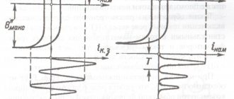
Grounding (Fig. 4.12) involves solid grounding of the neutral of a three-phase current source or transformer, one output of a single-phase current source, the presence of a neutral wire and its re-grounding.
Grounding the neutral of the current source is intended to reduce the voltage on the equipment housings and on the neutral wire to which these housings are connected to a safe value when the phase conductor is shorted to ground, thereby creating a path for the current Iph-z (Fig. 4.12).
The neutral protective conductor is designed to increase the short circuit current lk in order to influence this current on the protection. The increase in lк occurs due to a decrease in current resistance in the presence of a neutral wire compared to if the current flowed through the ground.
Re-grounding of the neutral wire is intended to reduce the voltage on equipment housings when a phase is shorted to the housing, both when the neutral wire is working and when the neutral wire is broken.
Grounding in electrical installations up to 1000 V is used in 4-wire networks with a solidly grounded transformer neutral
motor and generator, in networks with a grounded output of a single-phase current source, in networks with a grounded midpoint of a direct current source. Grounding is performed in the same cases as protective grounding.
The maximum resistance values of grounding devices in the grounding system are given in Table. 4.3.
Table 4.3 LIMIT VALUES OF RESISTANCE OF GROUNDING DEVICES IN THE GROUNDING SYSTEM
Zero working conductors are used as neutral protective conductors, with the exception of conductors for mobile electrical receivers. In the circuit of neutral protective conductors there should be no devices that disconnect these conductors, including fuses.
Grounding is checked for compliance with the requirements of the PUE during installation, upon delivery after installation and during operation.
Check the following parameters:
resistance of neutral and repeated groundings;
the ratio of the current of a single-phase short circuit to the body and the rated current of the fuse link or the setting current of the circuit breaker in the controlled section of the network, and this ratio must be at least 3, and for circuit breakers with only electromagnetic releases for a rated current of up to 100 A, the multiplicity must be at least 1, 4 and for machines with a current of more than 100 A - 1.25.
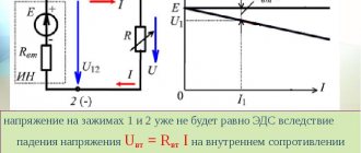
Safety shutdown
A residual current device (RCD) consists of a sensitive element that responds to changes in the controlled value, and an actuator that turns off the corresponding section of the network.
The sensing element can respond to housing potential, ground fault current, zero sequence voltage and current, and operational current. Contactors, magnetic starters, automatic switches with independent releases, and special switches for RCDs can be used as switches.
The purpose of the RCD is to protect against electric shock by turning off the device when there is a danger of a short circuit to the equipment body or directly when a person touches its leading parts.
RCD is used in electrical installations with voltages up to 1000 V with an isolated or solidly grounded neutral as the main or additional technical method of protection if safety cannot be ensured by using grounding or grounding or if grounding or grounding cannot be performed for some reason.
An RCD is mandatory for monitoring the insulation and shutting down the power plant when the insulation resistance decreases in power plants for special purposes, for example, in underground mines (leakage relay).
An example of an RCD is a protective-switching device of the ZOUP-25 type, designed to disconnect and switch on three-phase power circuits at a voltage of 380 V and a current of 25 A in systems with a solidly grounded neutral, as well as to protect people when touching live parts or equipment housings that are energized .
Electrical separation of networks
Electrical separation of networks is carried out through a special isolation transformer, which separates the network with an isolated or solidly grounded neutral from the section of the network that supplies the electrical receiver. In this case, the connection between the power supply network and the receiver network is carried out through magnetic fields; the receiver network section and the receiver itself are not connected to the ground. The isolation transformer is a special transformer with a transformation ratio equal to unity, a voltage of no more than 380 V, with increased reliability of design and insulation. The transformer is allowed to power no more than one receiver with a current of no more than 15 A. Step-down transformers with a secondary voltage of no more than 42 V can be used as isolation transformers if they meet the requirements for an isolation transformer.
Using low voltage
Low voltage (no more than 42 V between phases and in relation to ground) is used for hand tools, portable and local lighting in any room and outside. It is also used in rooms with increased danger and especially dangerous for powering local stationary lighting fixtures, if they are located at a height of less than 2.5 m. A common voltage in use is 36 V, and in closed metal containers a voltage of no more than 12 V should be used.
Potential equalization
As is known, touch or step voltage occurs when there is a potential difference between the base on which a person stands and the equipment bodies that he can touch, or between the legs. If you connect through additional electrodes and conductors the places where the human body might touch, there will be no potential difference and no associated danger.
Potential equalization of electrical equipment housings and associated structures and foundations is carried out by installing a contour grounding electrode, the electrodes of which are located around a building or structure with grounded or neutralized equipment. Inside the contour grounding system, under the floor of the room or platform, horizontal longitudinal and transverse electrodes are laid, connected by welding to the circuit electrodes. If there is a grounding, the circuit is connected to the neutral wire.
Potential equalization of equipment frames and structures is carried out by connecting the structures and all frames to the grounding or grounding network.
Potential equalization is used as an additional technical method of protection in the presence of grounding or grounding in areas with increased danger or especially dangerous ones.
The use of potential equalization is mandatory in livestock buildings.
The potential equalization device is carried out according to the project.
Characteristics of protective grounding
Electrical equipment has a part where current flows and a part where there is no current. It is the part where there is no current that is grounded. For this, special parts and conductors are used. Typically, they are made of iron or low carbon material. There are several types of grounding. So, you can use special electrodes that look like pins. They are inserted into the ground. It is prohibited to use aluminum parts to provide grounding. It is important to periodically check electrical equipment and grounding conditions.
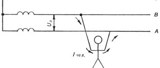
First aid for an electric shock victim
After releasing the victim from the action of electric current, it is necessary to determine his condition:
- consciousness: clear, absent, disturbed, agitated;
- color of the skin and visible mucous membranes (lips, eyes): pink, bluish, pale;
- breathing: normal, absent, impaired (irregular, shallow, wheezing);
- pulse in the carotid arteries;
- pupils are narrow and wide.
The color of the skin, the presence of breathing, and loss of consciousness are assessed visually. If the victim has no consciousness, breathing, pulse, the skin is bluish, and the pupils are wide, it can be considered that he is in a state of clinical death and it is necessary to immediately begin to revive the body using artificial respiration using the “mouth-to-mouth” or “mouth-to-mouth” methods. nose" and external cardiac massage.
If the victim breathes very rarely and convulsively, but his pulse is palpable, it is necessary to immediately begin artificial respiration.
Once you start reviving, you need to call a doctor or emergency medical help. If the victim is conscious, but was previously fainted or unconscious, but with stable breathing and pulse remaining, he should be laid on a mat, unbuttoned clothes, create an influx of fresh air, create complete rest, continuously monitoring the pulse and breathing.
Under no circumstances should the victim be allowed to move, much less continue to work, since there is no visible severe damage from electrical damage. current does not exclude a possible subsequent deterioration of his condition. The victim should be transferred to another place only in cases where he or the person providing assistance continues to be in danger or when providing assistance on the spot is impossible (for example, on a support). Under no circumstances should you bury the victim in the ground, as this will only cause harm and waste time.
Video
Types of electric shock
XXI CENTURY Candy Fudge Scented water
266 ₽ More details
Video baby monitor Motorola MBP36S (white)
12900 ₽ More details
Men's casual bags
In industrial settings
In production, to protect personnel from traumatic effects, special measures are used:
- simplicity and clarity of diagrams;
- equipment markings, inscriptions, colors;
- availability of first aid equipment;
- isolation transformers in which the windings must be separated;
- protective electrical separation;
- isolating rooms, platforms.
Note! For protective grounding, both natural grounding conductors are used - building structures in contact with the ground, pipelines, cable sheaths, rail tracks, and artificial ones.
Passive protection methods
Technical passive protection:
- Reliable conductor insulation (double or reinforced). Its thickness and material are calculated for specific conditions; the insulation must have an allowable resistance of at least 0.5 MOhm with one layer, with two layers 5 MOhm.
- Protective grounding is the connection of metal housings of equipment with a grounding element. The ground loop is in the ground.
- Reduce the supply voltage to a safe level (42 V).
- Use of protective equipment.
First aid for electric shock
Additional Information. All requirements for electrical protective insulating means are set out in the “Instructions for the use and testing of protective equipment used in electrical installations” dated 2003.
Funds are divided into basic and additional. The essence of the difference is that the main ones can withstand operating voltage, while the additional ones do not and are used only to enhance the insulating properties of the main ones. Depending on the voltage class of the installation, the means used.
Basic electrical protective equipment
When working with electrical equipment up to 1 kV, gloves made of dielectric material are used; they will be additional in devices over 1000 Volts. Extension ladders, fiberglass stepladders, dielectric carpets, insulating linings, caps and stands are included in the list of additional ones for both voltage classes.
Important! For each item, the order and frequency of mechanical and electrical tests are established. They must be inspected before each use to ensure they are not dirty or damaged. For example, gloves are twisted towards the fingers and made sure they are tight. Tested products are stamped with a stamp indicating the date of the next test.
General storage rules
Storage conditions must guarantee the integrity and preservation of the protective properties of PPE.
Rubber products should be stored in a warm (5 to 25 degrees) room with a humidity of 50 to 70%. Gas masks and tools must be kept in separate cases to protect them from moisture and other contaminants and to prevent mechanical damage.
In production, the chief electrician (or an employee appointed by a special order of the director) is responsible for monitoring the quantity and quality of personal protective equipment, as well as for compliance with the schedule for checking their condition through electrical tests.
In everyday conditions, it is enough to check gloves for mechanical damage (holes, cracks, abrasions), and similarly inspect safety shoes.
How to avoid electric shock
Maintenance of electrical installations
It is possible to avoid unpleasant consequences when working in electrical networks, subject to compliance with the Interindustry Rules on Occupational Safety and Health as they relate to the maintenance of electrical installations. In addition, the necessary electrical safety measures are regulated by a number of industry and national standards, one of which is represented by the current GOST 12.2.004–91. The provisions of these documents include the following sections:
- general safety precautions;
- organizational events;
- technical methods of protection.
They present rules for working with network equipment as a separate section.
The general provisions cover a wide range of issues, the main ones being:
- which personnel are covered by these rules;
- requirements for the condition of electrical installations in terms of equipping them with protective equipment;
- requirements for operational personnel, as well as features of maintenance of technical systems;
- general procedure of work and their documentary support.
Network requirements for labor protection determine the rules of work in industrial and household electrical networks. They relate to the maintenance and repair of electrical appliances of various classes. These include such common electrical installation products as energy meters, sockets, distribution boxes, and circuit breakers.
Local electrical injuries
Local electrical injuries are local violations of the integrity of body tissues. Local electrical injuries include: Electrical burn - current and arc:
• current - associated with the passage of current through the human body and is a consequence of the conversion of electrical energy and thermal energy.
• wind - at high voltages of the electrical network, an electric arc can form between the current conductor and the human body, resulting in a more severe burn, since the electric arc has a very strong burn. high temperature - over 3500°C.
Electrical signs (marks) are gray or pale yellow spots on human skin that form at the point of contact with a current conductor; as a rule, signs have a round or oval shape with dimensions of 1-5 mm; this injury does not pose a serious danger and goes away fairly quickly.
Metallization of the skin - penetration into the upper layers of the skin of the smallest particles of metal melted under the action of an electric arc; depending on the location of the injury, the injury can be very painful; over time, the skin peels off; eye damage can result in deterioration or even loss of vision;
Electroophthalmia - damage to the conjunctiva and skin of the eyelids due to the action of a stream of ultraviolet rays emitted by an electric arc; for this reason, you should not look at the welding arc; the injury is accompanied by severe pain and pain in the eyes, and temporary loss of vision.
Mechanical damage occurs as a result of sharp convulsive contractions of muscles under the influence of current passing through the human body; with involuntary muscle contractions, ruptures of the skin, blood vessels, as well as dislocations of joints and ruptures of ligaments can occur.
Fall protection
Much work in the energy sector is performed at heights. To ensure safety from falling or timely stopping, the following are used:
- anchor devices;
- safety harnesses;
- reinforcing and connecting subsystems.
All these elements are used as a kit and must meet the following requirements:
- stopping the fall is ensured by the harness due to the correct redistribution of the load;
- it should be possible to adjust the fit according to the individual characteristics of the worker (weight, height and even gender);
- reliability of fastenings and compliance of protective elements with the types and nature of work performed, as well as working conditions.
Work at height
The function of the reinforcing and connecting subsystem is to timely stop a falling worker. Modern means of protection use several types:
- slings with shock absorber;
- retractor blocks;
- sliders on rigid and flexible anchor lines.
Safety systems for working at heights use synthetic materials, the service life of which is designed for 2 years.
Enterprise workers who come into contact with electricity in their line of work should not ignore personal protective equipment in order to protect themselves from serious injury and avoid a threat to life. Management is obliged to strictly monitor compliance with this requirement, as well as the availability of the required amount of PPE and the frequency of their checks.
Basic safety measures
Carrying out electrical repair work requires great care and responsibility.
Personal protective equipment against electric shock
To avoid unexpected or indirect human contact with live parts, it is necessary to provide basic measures of protection against electric shock. These include:
- Mandatory presence of solid insulation that prevents direct contact with exposed elements of electrical conductors;
- A restrictive barrier for unauthorized persons to access electrical power equipment and electrical installations. The protective fence must be durable and equipped with locking elements and combination locks;
- To avoid physical contact during inspection, it is necessary to install live parts at a considerable distance from each other;
- Use of lighting devices operating at low voltage from 12 to 36 W for electrical lighting of power electrical installations. The same voltage is recommended for the electric drive of the necessary power tools. For this purpose, step-down transformers are used with their secondary winding grounded.
In addition to the main list of protective safety measures, in order to avoid electric shock to a person, an electrical potential equalization system and an automatic shutdown device (RCD) are used.
Automatic shutdown device (RCD)