The use of timers allows you to program the operation of household appliances for various periods of time. We can talk about boilers, kettles, air conditioners and many others. When choosing a suitable time relay, you need to understand what characteristics you need to pay attention to and know how to find a model that is best suited to specific operating conditions.
Some keyboard devices are capable of controlling several devices simultaneously Source sovet-ingenera.com
What are timers?
They provide certain signals to various devices at precisely specified times. The nature of household appliances or industrial equipment in the implementation of control is not decisive.
A switch with a shutdown timer can operate for short periods of time or be controlled over a period of days, weeks or months. The technician must ensure proper electrical connections. When programming, you need to set the time when the signal should be given.
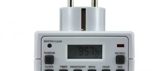
Sometimes such time relays have additional useful properties. For example, a timer for a kettle or coffee maker may be located in the same housing as the socket. Thus, the owner can easily immediately set the temporary parameters of the device.
Electronic devices use a display and several keys Source sovet-ingenera.com
What are they used for?
The use of time relays is common in domestic conditions. For example, when operating an air conditioner, actions may be required that are carried out cyclically at certain intervals. For example, cooling or heating (depending on weather conditions), which are performed with an hour break.
The switch will help you warm up your food before dinner. If the owner leaves the house for some time during the cold season, it is better for him to turn off the heating. But if he only does this for a couple of days, he can arrange for it to be turned on periodically with minimal parameters.
Socket type timer Source sovet-ingenera.com
Features of the timer
The use of a time relay will not only help to rationally control household appliances, but will also save energy. For example, it is possible to use a switch with a time delay. A high-quality device must have the following characteristics:
- It is necessary that the timer operates for a period of time sufficient to complete the planned tasks. The relay can, for example, be used to control a kettle for the next hour or over several weeks to regulate the operation of a heating boiler.
- All necessary control functions must be provided to ensure full operation of the equipment.
- High accuracy of the built-in clock is required. When a signal is given, there should not be a time difference between the receipt of the command and the activation of those relays that provide activation or deactivation of the corresponding equipment.
- The timer must have sufficient discreteness to accurately carry out the programmed actions.
This instrument is a complex electronic device that can be programmed by the user for various purposes.
Electromechanical timer Source sovet-ingenera.com
Time relay 12v
Algorithm of operation of the time relay in version No. 2: After power is supplied to the supply contacts of the timer, the set time begins counting (0-6000 sec), but the power relay coil does not turn on immediately and only after the set time has passed, power is supplied to the power executive relay coil and it is held, as long as there is power at the supply contacts of the timer and the executive contacts turn on or off the load accordingly.
The next time cycle will occur after a short power outage at the timer power contacts: No. 15. The diagram of the timer operation algorithm in version No. 2 is shown in Figure No. 2. Operating logic of a 12V time relay (timer) in version No. 3: When power is applied to the power contacts of timer No. 15, the power executive relay is turned on, but time is not counted; after the power is turned off, the countdown of the set time 0-6000 seconds begins from contact No. 15 and then After the set time has elapsed, the power to the power executive relay coil is turned off and the load is turned on or off accordingly. Attentively!!! The timer circuit only works when there is positive voltage at power contact No. 30. The operating algorithm diagram of the time relay in version No. 3 is shown in Figure No. 3. Timer operation logic in version No. 4: allows you to select the timer operation algorithm and time range by switching and combines timers in versions No. 1, No. 2 and No. 4. Operation in version No. 4 ("Start" button): When power is applied, nothing turns on, after pressing the "Start" button, the time countdown begins, after the set time has elapsed, the power to the coil of the power executive relay is turned off, the contacts of which turn on or off the load. The next operating cycle will occur after briefly pressing the “Start” button.
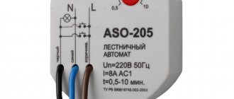
price 550 rubles Universal digital timer with 12 volt power supply. The time relay operates in delay mode or cyclic mode in the time range from 0.01 seconds to 999 minutes. LED digital indicator. timer power supply from 12 volts.
price 850 rub. Photo of timer UT12v
| Name | Price | Applicability | |
| Block 45 7373 9007 with wires | 45.60 | 4-pin | |
| Relay block 45 7373 9016 with wires | 49.10 | 5 pin | |
| Relay block 45 7373 9078 with wires | 50.20 | 5 pin | |
| Block 45 7373 9095 with wires | 50.20 | 6 pin | |
| RAGTIME1-12-(0-60) (for on/off devices at 0-60s) | 350.00 | Cars of any brand and equipment with 12V voltage | |
| RAGTIME1-24-(0-60) (for on/off devices at 0-60s) | 350.00 | For cars of any brand and devices with a voltage of 24 volts | |
| RAGTIME2-12-(0-60) (for turning on/off devices after 0-60s) | 350.00 | Suitable for any brand of car with on-board voltage 12 | |
| RAGTIME2-24-(0-60) (for turning on/off devices after 0-60s) | 350.00 | Can be used in a car with 24V on-board voltage | |
| RAGTIME1-12-(60-600) (for on/off devices at 60-600s) | 350.00 | Used to keep track of time in a car with an on-board voltage of 12 volts | |
| RAGTIME1-24-(60-600) (for on/off devices at 60-600s) | 350.00 | Timer for cars of any brand with 24V on-board voltage | |
| RAGTIME2-12-(60-600) (for turning devices on/off after 60-600s) | 350.00 | The time relay can be installed in a car of any brand with a 12V network voltage | |
| RAGTIME2-24-(60-600) (for turning on/off devices after 60-600s) | 350.00 | Cars of any brand with 24V on-board voltage | |
| RAGTIME3-12-(0-60) (for turning on/off devices after 0-60s) | 350.00 | Cars of any brand with 12V on-board voltage | |
Types of devices
Mechanical timers have a dial with petals arranged in a circle. Each of them corresponds to a certain time. The resolution is 15 or 30 minutes. By combining pressed or released paddles, you can set when the equipment will be turned on and when not. There are also brands whose controls are based on rotating a special wheel and using several levers. One simple option is a time delay switch.
The main advantage of the device is its simple design. Low discreteness and the lack of ability to implement complex algorithms limit the use of this device.
The video will help you understand how to choose a time relay:
Video description
How to choose a timer, time relay, their types and operating principle.
The basis for timing is the operation of the built-in motor. These sleep timers must have a power source to operate. With regular use, the gears of the wheel used to make time settings can quickly wear out.
Timer with on-delay Source sovet-ingenera.com
Cyclic time relays (asymmetrical pulse generators)
The main electronic time relays used are relays with on- and off-delay functions, cyclic time relays, and relays with a time delay after removing the supply voltage.
The cyclic time relay is designed for switching electrical circuits through relay contacts after working out preset time delays (“pauses” and “pulses”)
The following parameters can be adjusted in the relay:
- time ranges of pause and pulse exposures,
- starting a cycle from a pause or from an impulse, or from an external trigger
In this review, we will consider the main types of cyclic time relays from various manufacturers of relay equipment. At the moment there are many multifunctional relays with cyclic relay functions, but we will consider only a few of them, i.e. cyclic relays whose functionality allows you to set the duration of the pulse and pause independently in a wide time range.
Time relay VL-65 (Ukraine)
VL-65 cyclic time relay is designed for switching electrical circuits with certain, preset time delays. (cyclic with pause)
Independent smooth adjustment of pulse duration and pause.
Time range:
- pulse: from 0.1s to 30h
- pause: from 0.1s to 30h
Output contacts, switching current, supply voltage:
- 1 NO and 1 NC, 4A, 110 50Hz, 220V 50Hz
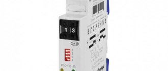
Time relay RSV-15-3 (VNIIR, Cheboksary)
RSV-15-3 time relay is designed for switching electrical circuits with certain, preset time delays and is used in automation circuits as a component product. The relay has a continuously adjustable time delay.
Time range
- impulse:(0.1..1; 0.3..3; 1..10; 3..30)s,min,h
- pause: (0.1..1; 0.3..3; 1..10; 3..30)s, min, h
Output contacts, switching current, supply voltage:
- 1 NO and 1 NC with time delay, 3A,
- 24,110,220V DC, 110,220V AC.
Time relay VL-42M1.
The VL-42M1 cyclic time relay allows you to set the pulse and pause durations independently in a wide time range from 0.1 s to 99 hours. The relay has a control input for stopping the timing, 1 normally open contact and one changeover contact. The relay power supply is universal (24…220V DC or AC).
functions of relay VL-42M1:
- cyclic from pause / from pulse
- cyclic from pause / from pulse with stop
Time range
- 0.1s…99h
Output contacts, switched current. supply voltage:
- 1 NO and 1 changeover
- 24…220V DC and AC
Cyclic time relay RSV-01 (Cheboksary)
The cyclic time relay RSV 01-5 is intended for switching electrical circuits of automation and control circuits of equipment for various purposes. Time relays are widely used at enterprises of various profiles in the technological cycle of equipment operation, in the energy sector, in automation and control systems, and in advertising installations.
(cyclic single-chain, with adjustable pulse and pause duration)
Cyclic relay RVTs-P2-08 ACDC24-240V (St. Petersburg)
Cyclic time relay RVTs-P2-08 (RVTs-08) is designed for switching electrical circuits with preset time delays (pause and pulse).
- Time range: pulse, pause: 0.1 sec -99 hour, divided into 8 subranges
- Number of contacts 2 switching groups, 5A. power supply: ACDC24-240V
Cyclic relay RVTs-P3-14 ACDC24B/AC220B (St. Petersburg)
Cyclic time relay RVTs-P3-14 (RVTs-14) is designed for switching electrical circuits through relay contacts after working out preset time delays (“pause” and “pulse”).
- Time range: pulse, pause: 0.01 sec -999 min, divided into 4 subranges
- Number of contacts: 2 changeover groups + instantaneous changeover contact, 7 A, ACDC24B/AC220B
Time relay REV-201M (St. Petersburg)
Relay REV-201M is designed for switching electrical circuits of alternating current 220V 50 Hz and direct current 24-100V with an adjustable time delay. The relay contains two channels. Each channel can operate according to four operating algorithms specified by the user: - turn-on delay; — pulse mode; — cyclic mode with pause; — control relay mode*.
Time range
- 0…36 000s
Output contacts, switching current, supply voltage:
- 1P in each channel, 7 A
- 160…300V AC
- 21.6…26.4V DC
Multifunctional time relay PCU-520 (Belarus)
Microprocessor time relay PCU-520 is designed to control consumers (load) in industrial and household automation systems.
Relay functions:
- on/off delay
- cyclic operation with on/off delay
2 changeover contacts, 8A, supply voltage 230V 50Hz
FINDER - 80.91.0.240.0000, 83.91.0.240.0000 (Italy)
Asymmetric pulse generator D6 24 V AC/ DC 110-240 V AC (Austria)
D6DI is a 2-time multifunctional timer, asymmetric pulse generator.
Functions D6DI 24VAC/DC 110-240VAC
- asymmetric pulse generator starting from a pause
- asymmetric pulse generator starting from pulse (selectable by jumper)
- 1 changeover contact, 5A
Asymmetric pulse generator E1 ZI10 12-240 V AC/ DC (Austria)
Relay E1ZI10 - 2-time multifunctional timer, asymmetric pulse generator.
- Generator asymmetric pulses starting from pulse (selectable by jumper)
- Asymmetric pulse generator starting from a pause (selectable by jumper)
- 7 time ranges
- Supply voltage from 12 to 240V AC/DC
- 1 changeover contact, 8A
Asymmetric cycler CRM-2 (Czech Republic)
The asymmetrical cycler (cyclic relay) CRM-2H is used to regularly turn on and off devices for a given period of time. The period of turning the output on and off is set, and the cycler regularly turns off and turns on the controlled electrical appliances.
- Supply voltage AC/DC 12 - 240 V or AC 230 V,
- Duration range 0.1 sec – 100 days
- output contact: 1x changeover 16 A.
Asymmetrical pulse generator TRC01 (Czech Republic)
TRC01 is an asymmetrical pulse generator. Multifunctional time relay – asymmetrical pulse generator, with a start on a pulse or a pause. Time setting is possible in the range from 0.1 seconds to 10 days.
- supply voltage: 12 … 230 V AC/DC (+10/15%)
- 1 x changeover contact, 8A
Almost all cyclic relays have a control function with a contact group with a rated current of 5 to 8A (16A - CRM-2 , type 80.91 ) therefore, for connection, manufacturers recommend using intermediate relays designed for a specific load, that is, for large loads an additional power relay is required (intermediate relay / contactor/starter). All these devices will help you regularly ventilate rooms, get rid of humidity, control lighting, illuminated advertising or control circulation pumps, regularly turn off and turn on controlled electrical appliances.
Video description
Mechanical timer for turning on and off the lighting in the aquarium.
In the first case, problems may arise if there is a power failure. However, such timers can work for a very long time without requiring special attention. Devices that use a battery have a significant degree of autonomy, but operate for a limited time until the charge runs out.
Programmable timer for controlling household appliances Source 220.guru
For each such device, in practice, a certain operating mode is established. It is important that the one that the owner needs is provided for this device. The most common are the following:
- A universal timer allows you to plan work algorithms within a wide range.
- Random switching may be used.
- Countdown time is applied.
- An astronomical countdown is underway.
- Using weekly rhythms. For example, if you need to regularly perform actions on certain days of the week.
- Actions based on circadian rhythms.
Cyclic time relay
When selecting a time relay for “one craft,” several different modifications were purchased. In the review, a variant of a cyclic time relay. It all started with the search for a relay with a certain type of operation (according to the PS code - FE mode was required). It will probably be unnecessary to go into the details of this mode of operation in this review (later there will be a more interesting review with details of the types and the device built), so I’ll skip a little further... During the search process, I realized that it WILL be possible to get diagrams of relay operation or even a simple answer to the question from sellers IT IS almost impossible to WORK in a given mode. Therefore, several trial orders of various relay modifications were made in order to test their capabilities and try to assemble the device I needed from them. Below is a description of one of the purchased samples. This is a relay version with cyclic state switching during the entire power supply time. Options for using all kinds of switching on thermostats, lighting, etc. After purchasing and testing, I realized a number of mistakes when choosing, one of them, for example, is the need to select a relay board with three input contacts to be able to supply control pulses to get the result I need. But what I got is what I got, I decided to share the details of the work - perhaps it will be useful for someone when choosing similar relays for their purposes.
Appearance of the relay and its dimensions
Assembled on STC15W202S, convenient terminal blocks for wires are installed for integration into circuits.
dimensions... The quality of soldering is average - there are voids, and in general the impression of “dry soldering” with an insufficient amount of flux.
First of all, the functionality of the device was checked.
In principle, everything is fine, I had to figure out the controls a little, below I will describe the functions and purpose of the buttons.
There are two buttons labeled K1 and K2. In the initial position, K1 enters the settings and K2 switches the delay time range, there are several options selected cyclically in a circle - 99.9 sec, 999 sec, 9999 sec. Those. You can select from 0.1 sec to 9999 sec for both the on and off time of the relay. When entering the settings mode (pressing K1 once), the K1 button begins to perform the function of “entering” and selecting mode settings (on or off relay state) and the K2 button scrolls through values. In short, everything is extremely simple and easy to understand.
This relay code PS is LI (Asymmetric Loop Repeat (Initial Pulse ON)) Power is supplied to the timer. The output contacts operate immediately and switch between ON and OFF positions as long as power is supplied. The dwell time in the closed (Ta) and open (Tr) states is independently adjustable. Diagram of operation of this relay
Ta and Tr as I wrote above, it is possible to adjust from 0.1 sec to 9999 sec.
When the relay is operating, the indicator constantly contains indications of the remaining time before changing the operating mode and an indication of operation (blue LED) and 12V power supply (red LED). The relay has a normally closed and normally open contact with a stated switching current of up to 10A. Below is a short video of the work. Cons: soldering, lack of instructions and operation diagrams. Pros - A fully functional cyclic relay with a reasonable price tag. It can be recommended for use in various automation systems using its capabilities. Convenient terminal blocks for connecting to circuits. Relatively large switched load current. Possibility of switching with power supply isolation.
How to choose the right model
The timer must be suitable for the tasks for which it is purchased. When exploring these options, consider the following:
- What supply voltage is the product designed for?
- Type of control when determining the operating algorithm of the device. You can choose a mechanical or electronic option.
- The purchased time relay provides a certain installation option. It can be socket, using a junction box or another. You need to choose the one that is suitable for the application.
- It is necessary to take into account the degree of security of the device. In some cases, for example, devices that are waterproof may be required.
- You need to pay attention to the length of the period during which you can program the timer.
If we are talking about an option that uses mains power, then it needs to be insensitive to voltage failures. These devices can provide a wide variety of functions. You need to make sure that among them there are those that are needed.
Socket with remote control Source kupisantehniki.ru
The simplest 12V timer.
Hello! For a very long time, my car from the German auto industry lacked a function that I really needed. Namely, that when closing with the remote control on the key, the windows were not closed (the so-called squeeze). That is, if the key is inserted into the lock, turned to lock and held, then the car will close and the windows will also close. But from the button - well, no way! This is such a German trick. And I have 7 vents.
When I purchased this car 7 years ago, I was immediately puzzled by this problem. I've read all the forums. But there is no result - this function is not available. And finally I got my hands on it.
I couldn’t think of a better way to prolong the signal from the key remote control, so I ordered this timer. It’s quite inexpensive, and if I can’t make friends with the car, I won’t be too upset.
The order was placed on June 19 (!), but received only a week ago. Without tracking, delivery by Georgia Post.
A simple package, antistatic inside with a timer board.
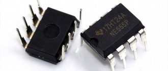
Implemented on MS NE 555, a well-known timer. Characteristics :
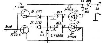
1. Power supply 12 V, 2. Shutdown delay time from 0 to 10 sec., 3. Relay with “dry” contacts, can be switched 250 V 10 A, 4. LED status indicators, 5. Possibility to set a different control limit by replacing C 1 .
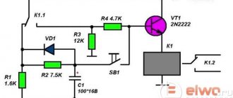
I didn’t draw a diagram based on the board; the NE 555 switching circuits are almost the same type. I found an approximate diagram in the open spaces, a slight difference in the hanging elements.
Soldering and appearance are good. The board is double-sided, mounting on one side. Dimensions 7 cm X 2 cm X 2 cm.
Double block - VCC(+) and GND(-) 12 V power supply. Triple block - NO (normally open contact), COM (common) and NC (normally closed contact).
I checked the battery operation of the screwdriver. When power is applied, the timer immediately starts and counts down the set interval. Red LED indicates circuit power supply, green LED indicates countdown. After reaching the specified shutdown threshold, the green diode goes out and the relay returns to its original state.
Restarting the timer is possible after removing and reapplying the supply voltage or installing an additional button between the (-) power supply and the 2nd leg of the MS.
Well, I checked the timer, turned the trimmer to the maximum 10 seconds and went to disassemble the car.
I took the trim off the door. The lock comes with a wiring harness. Among them I find constants (+ and -) to power the timer. I will switch the minus through the limit switch for reset and so that the board is energized only when the car is set to alarm.
I connect the power to the board.
There is still one connector on the lock. It is connected to the microswitches of the cylinder. One closes the car, the other opens it. The (+) power supply is switched. This is the plus I need. I will duplicate the holding with the key using the contacts of the timer relay.
I find a wire (you won’t get confused in three wires) that is responsible for closing and pressing the windows and cut it. Just in case, I solder in an isolation diode.
I solder a diode onto the board for the same purpose, having previously cut the track from the relay output. Maybe the diodes are unnecessary, but I played it safe. So that (+) does not fly to the relay when closing with a physical key and back when closing using a timer.
All that remains is to set the limit switch to turn on and reset the timer. Found this in an old tape recorder. I found the installation location experimentally. Minimal interference with the lock mechanism (only a small screw was screwed into the moving part).
I check and secure the board with ties to the standard harness holder.
All! All windows can be closed using the remote control! To say that I am pleased is to say nothing. The cost is 70 rubles and a couple of hours of time spent. And there was no need to get into the “brains” of the central locker.
A short video of work -
Thank you everyone and happy shopping!