One of my friends gave me the idea to make an electric bicycle with my own hands. At first the idea seemed strange to me, but then I got into it and even got excited. At the final stage of assembly, I had almost everything ready, all that was left was the PWM regulator. For some reason I also wanted to make it myself. I’m quite pleased with the result, so next I’ll tell you how to make a PWM controller for an electric motor with your own hands.
Source prom.st
About PWM regulator
PWM (PWM) controller for wide application - a device designed for smooth switching on, off and adjustment of power, speed, brightness and more.
Previously, to regulate the speed of electric motors, the supply voltage was changed. However, in modern electrical engineering this has been abandoned. Now the adjustment occurs by applying current pulses to the electric motor, which have different durations. This is what PWM (pulse width modulated) regulators do, which have recently become more and more popular.
PWM controller circuits are universal - they are suitable for adjusting the brightness of lamps, and for adjusting the speed of motor revolutions, and even for regulating the current strength in the charger.
The scope of application of PWM regulators is very wide.
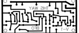
Review of the board
Assembled homemade PWM regulator board:
Source prom.st
The board is controlled manually and is carried out by a variable resistor or external voltage in the ranges:
0.45 V – device is turned off, duty cycle is 0%
0.5/3.5 V – smooth regulation, duty cycle from 0.1% to 99.9%
3.6 V – device on, duty cycle – 100%
The device operates at a constant voltage of 10 to 28 Volts.
The maximum voltage is limited by the maximum permissible voltage of the power switches, as well as the reverse voltage of the high-power diode in the load, when separate from the additional 15 V control power supply.
I advise you not to install a stabilizer if the voltage does not reach 15 Volts.
Instead, some kind of diode or regular jumper would be better.
If the voltage is from 15 to 28 Volts, then it is worth installing a linear (for example, 7815) or pulse stabilizer in the form of a ready-made module on the MP2307, and you must set the voltage on it to 15 Volts.
You can order them on the same Aliexpress.
If necessary, you can adjust the frequency with a continuously variable resistor.
To do this, you need to connect it to the board instead of a jumper.
Electronics for everyone
I needed to make a speed controller for the propeller. To blow away the smoke from the soldering iron and ventilate the face. Well, just for fun, pack everything into a minimum price. The easiest way to regulate a low-power DC motor, of course, is with a variable resistor, but to find a motor for such a small nominal value, and even the required power, it takes a lot of effort, and it obviously won’t cost ten rubles. Therefore, our choice is PWM + MOSFET.
I took the key IRF630 . Why this particular MOSFET ? Yes, I just got about ten of them from somewhere. So I use it, so I can install something smaller and low-power. Because the current here is unlikely to be more than an ampere, and the IRF630 is capable of pulling through itself under 9A. But it will be possible to make a whole cascade of fans by connecting them to one fan - that’s enough power. Now it’s time to think about how we’ll use PWM . The thought immediately suggests itself - a microcontroller. Take some Tiny12 and do it on it. I threw this thought aside instantly.
- I feel bad about spending such a valuable and expensive part on some kind of fan. I'll find a more interesting task for the microcontroller
- Writing more software for this is doubly frustrating.
- The supply voltage there is 12 volts, lowering it to power the MK to 5 volts is generally lazy
- The IRF630 will not open from 5 volts, so you would also have to install a transistor here so that it supplies a high potential to the field gate. Fuck it.
What remains is the analog circuit.
Well, that’s not bad either. It doesn’t require any adjustment, we’re not making a high-precision device. The details are also minimal. You just need to figure out what to do. Op amps can be discarded outright. The fact is that with a general-purpose op-amp, already after 8-10 kHz, as a rule, the maximum output voltage begins to drop sharply, and we need to jerk the field worker. Moreover, at a supersonic frequency, so as not to squeak.
Op-amps without such a drawback cost so much that with this money you can buy a dozen of the coolest microcontrollers.
Into the furnace! What remains are comparators; they do not have the ability of an op-amp to smoothly change the output voltage; they can only compare two voltages and close the output transistor based on the results of the comparison, but they do it quickly and without blocking the characteristics. I rummaged through the bottom of the barrel and couldn’t find any comparators. Ambush! More precisely, it was LM339 , but it was in a large case, and religion does not allow me to solder a microcircuit for more than 8 legs for such a simple task. It was also a shame to drag myself to the storehouse. What to do?
And then I remembered such a wonderful thing as an analog timer - NE555 . It is a kind of generator where you can set the frequency, as well as the pulse and pause duration, using a combination of resistors and a capacitor. How much different crap has been done on this timer over its more than thirty-year history... Until now, this microcircuit, despite its venerable age, is printed in millions of copies and is available in almost every warehouse for a price of a few rubles. For example, in our country it costs about 5 rubles. I rummaged through the bottom of the barrel and found a couple of pieces. ABOUT! Let's stir things up right now.
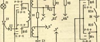
How it works If you don’t delve deeply into the structure of the 555 timer, it’s not difficult. Roughly speaking, the timer monitors the voltage on capacitor C1, which is removed from the THR (THRESHOLD - threshold). As soon as it reaches the maximum (the capacitor is charged), the internal transistor opens. Which closes the DIS (DISCHARGE - discharge) pin to ground. In this case, a logical zero appears at the OUT . The capacitor begins to discharge through DIS and when the voltage across it becomes zero (full discharge), the system will switch to the opposite state - at output 1, the transistor is closed. The capacitor begins to charge again and everything repeats again. The charge of capacitor C1 follows the path: “ R4->upper arm R1 ->D2 ”, and the discharge along the path: D1 -> lower arm R1 -> DIS . When we turn the variable resistor R1, we change the ratio of the resistances of the upper and lower arms. Which, accordingly, changes the ratio of the pulse length to the pause. The frequency is set mainly by capacitor C1 and also depends slightly on the value of resistance R1. Resistor R3 ensures that the output is pulled to a high level - so there is an open-collector output. Which is not able to independently set a high level.
You can install any diodes, the conductors are approximately the same value, deviations within one order of magnitude do not particularly affect the quality of work. At 4.7 nanofarads set in C1, for example, the frequency drops to 18 kHz, but it is almost inaudible, apparently my hearing is no longer perfect 
I rummaged around in the bins, found a program that itself calculates the operating parameters of the NE555 timer and assembled a circuit from there, for astable mode with a fill factor of less than 50%, and screwed in a variable resistor instead of R1 and R2, with which I changed the duty cycle of the output signal. You just need to pay attention to the fact that the DIS output (DISCHARGE) is connected to ground through the internal timer switch, so it could not be connected directly to the potentiometer , because when twisting the regulator to its extreme position, this pin would land on Vcc. And when the transistor opens, there will be a natural short circuit and the timer with a beautiful zilch will emit magic smoke, on which, as you know, all electronics work. As soon as the smoke leaves the chip, it stops working. That's it. Therefore, we take and add another resistor for one kilo-ohm. It won’t make a difference in regulation, but it will protect against burnout.
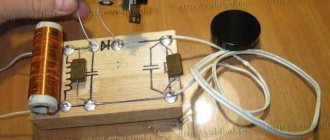
No sooner said than done. I etched the board and soldered the components:
The timer itself is hidden by the massive body of the transistor. I had to bend it so that it wouldn’t stick out.
I soldered a protective diode that protects the field device from breakdown when the load is interrupted on the motor itself.
Everything is simple from below. Here I am attaching a signet, in my native Sprint Layout - PWM.lay
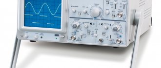
I turn it on... I poke it with an oscilloscope and see the following pictures:
This is at the output of the capacitor. We had a drink here. Initially, I wanted to install the 555 timer simply as a saw generator, and do the PWM on a comparator, but then I realized that I could do without a comparator.
And this is the voltage at the output of the timer itself. At different twist positions
Far left
Middle
Far right
And this is the voltage on the engine. A small transition process is visible. You need to put the conduit in parallel at half a microfarad and it will smooth it out.
As you can see, the frequency floats - this is understandable, because in our case the operating frequency depends on the resistors and capacitor, and since they change, the frequency floats away, but this does not matter. Throughout the entire control range, it never enters the audible range. And the entire structure cost 35 rubles, not counting the body. So - Profit!
Homemade controller circuit
This circuit contains a minimum number of components in the circuits of the microcircuits:
Source usamodelkina.ru
The main PWM controller from 0% to 100%, which will control all the power in the load, is assembled on a TL494 chip.
With this switching option, the internal offset is compensated to create dead time.
When switching high currents, strong interference occurs.
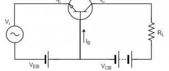
An isolated +15 Volt -12 Volt power supply with additional overload protection is assembled on the NE555 chip.
The main task is to regulate secondary voltages by changing the frequency.
Depending on the load, it operates at a frequency in the range of 120-480 kHz.
In case of overload, the pulse width, as well as the frequency, is reduced.
If there is no load, the positive arm on the transformer tends to 25 volts, and the negative voltage decreases until it reaches zero.
If there is no load on the transformer, then either the driver is not connected or it is idle.
To reduce noise and load on the wires by cutting off reactive energy, you should install a freewheeling load diode in close proximity to the load itself.
In this case, you can use conductors whose cross-section is smaller than those used when installing the diode away from the load.
Source ytimg.com
How to make it yourself
If you don’t want to spend money on purchasing a ready-made device, you can make it yourself. This way, you can not only save money, but also gain useful experience. So, to make a thyristor regulator you will need:
- soldering iron (to check functionality);
- wires;
- thyristor, capacitors and resistors;
- scheme.
As can be seen from the diagram, the regulator controls only 1 half-cycle. However, for testing performance on a regular soldering iron, this will be quite enough.
If you don’t have enough knowledge to decipher the diagram, you can familiarize yourself with the text version:
The use of regulators allows for more economical use of electric motors. In certain situations, such a device can be made independently. However, for more serious purposes (for example, monitoring heating equipment), it is better to purchase a ready-made model. Fortunately, there is a wide selection of such products on the market, and the price is quite affordable.
Based on the powerful triac BT138-600, you can assemble a circuit for an AC motor speed controller. This circuit is designed to regulate the rotation speed of electric motors of drilling machines, fans, vacuum cleaners, grinders, etc. The motor speed can be adjusted by changing the resistance of potentiometer P1. Parameter P1 determines the phase of the trigger pulse, which opens the triac. The circuit also performs a stabilization function, which maintains engine speed even under heavy load.
For example, when the motor of a drilling machine slows down due to increased metal resistance, the EMF of the motor also decreases. This leads to an increase in voltage in R2-P1 and C3 causing the triac to open for a longer time, and the speed increases accordingly.
Controller testing
One way to use this controller is to smoothly control the speed of an electric motor.
In this case, you don’t have to remove the standard discrete speed control circuit - it remains, is not disturbed and continues to work.
The circuit is connected with only three wires: plus at 12 volts, ground and the wire of the electric motor itself.
The board can also be used to replace the switch and quenching resistor in the original circuit.
First of all, when testing, make sure that all parts are in place and securely fastened.
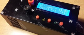
Next, the manufactured PWM controller for the electric bicycle motor must be simultaneously connected to both the battery and the bicycle motor, which will set it in motion.
Use a set of lithium battery cells with a nominal voltage of 80 Volts (these batteries are used in electric bicycles).
By turning the potentiometer clockwise, your bike's engine will gradually begin to rotate, and its speed will increase in proportion to the rotation of the handle.
If everything is in order, then your homemade PWM controller is assembled correctly.
Source ytimg.com
I recommend the following video, in which the author makes a PWM regulator with his own hands:
Operating principle of pulse converters
Operating principle of a pulse stabilizer
The main principle of operation is that when the regulating element is closed, electrical energy is accumulated in the integrating element. This accumulation is observed by increasing voltage. After the control element is switched off, i.e. opens the electricity supply line, the integrating component releases electricity, gradually reducing the voltage. Thanks to this method of operation, the pulse stabilization device does not consume a large amount of energy and can have small dimensions.
The regulating element can be a thyristor, a bipolar transient or a field-effect transistor. Chokes, batteries or capacitors can be used as integrating elements.
Note that pulse stabilization devices can operate in two different ways. The first involves the use of pulse width modulation (PWM). The second is a Schmitt trigger. Both PWM and Schmitt trigger are used to control the switches of the stabilization device.
As a result…
Do-it-yourself PWM controller is ready. Assembling it will not be difficult for anyone who has at least a little knowledge of radio engineering. I built my controller for use in an electric bike motor, but it can be used for more than just motors. This is a universal device - suitable for adjusting the brightness of the lamps, the speed of the motor, and the current in the charger.
Question
Write in the comments how reliable do you think PWM controllers from Aliexpress are?
Comments:
Metelkin
The article is good. It should be added that the pulse stabilizer is designed for low current, i.e. There is no way to connect a TV or computer through it, only a light bulb or some kind of cooler.
Romka
Does anyone know the circuit diagram of a stabilizer for an energy-saving light bulb and is it profitable to assemble it yourself? How much cheaper/more expensive is it than buying a new lamp?
Pashka
Which capacitor should be installed in the electricity storage unit for the stabilizer?
Leave a comment Cancel reply
Similar posts
Electrical appliances for home and industrial use
Voltage stabilizer - how to choose for a heating boiler. Stabilizer Era STA 3000 - a device for the home Voltage stabilizer 220 - reliable operation of equipment in the house.
Adjustment
Now let's talk about how you can regulate the speed of commutator motors. Due to the fact that the rotation speed of the motor simply depends on the amount of voltage supplied, any means of adjustment that are capable of performing this function are quite suitable for this.
Let's list a few of these options as examples:
- Laboratory autotransformer
(LATR). - Factory control boards
used in household appliances (you can use, in particular, those used in mixers or vacuum cleaners). - Buttons
used in the design of power tools. - Household
lighting regulators with smooth action.
However, all of the above methods have a very important flaw. Along with the decrease in speed, the engine power also decreases. In some cases, it can be stopped even just with your hand. In some cases, this may be acceptable, but in most cases, it is a serious obstacle.
A good option is to adjust the speed using a tachogenerator.
It is usually installed at the factory. If there are deviations in the motor rotation speed, an already adjusted power supply corresponding to the required rotation speed is transmitted to the motor. If you integrate motor rotation control into this circuit, then there will be no loss of power.
How does this look constructively? The most common are rheostatic rotation control, and those made using semiconductors.
In the first case, we are talking about variable resistance with mechanical adjustment. It is connected in series to the commutator motor. The disadvantage is the additional heat generation and additional waste of battery life. With this adjustment method, there is a loss of engine rotation power. Is a cheap solution. Not applicable for sufficiently powerful motors for the reasons mentioned.
In the second case, when using semiconductors, the motor is controlled by applying certain pulses. The circuit can change the duration of such pulses, which in turn changes the rotation speed without loss of power.
How to make it yourself?
There are various options for adjustment schemes. Let us present one of them in more detail.
Here is how it works:
Initially, this device was developed to adjust the commutator motor in electric vehicles. We were talking about one where the supply voltage is 24 V, but this design is also applicable to other engines.
The weak point of the circuit, which was identified during testing of its operation, is its poor suitability at very high current values. This is due to some slowdown in the operation of the transistor elements of the circuit.
It is recommended that the current be no more than 70 A. There is no current or temperature protection in this circuit, so it is recommended to build in an ammeter and monitor the current visually. The switching frequency will be 5 kHz, it is determined by capacitor C2 with a capacity of 20 nf.
As the current changes, this frequency can change between 3 kHz and 5 kHz. Variable resistor R2 is used to regulate the current. When using an electric motor at home, it is recommended to use a standard type regulator.
At the same time, it is recommended to select the value of R1 in such a way as to correctly configure the operation of the regulator. From the output of the microcircuit, the control pulse goes to a push-pull amplifier using transistors KT815 and KT816, and then goes to the transistors.
The printed circuit board has a size of 50 by 50 mm and is made of single-sided fiberglass:
This diagram additionally shows 2 45 ohm resistors. This is done for the possible connection of a regular computer fan to cool the device. When using an electric motor as a load, it is necessary to block the circuit with a blocking (damper) diode, which in its characteristics corresponds to twice the load current and twice the supply voltage.
Operating the device in the absence of such a diode may lead to failure due to possible overheating.
In this case, the diode will need to be placed on the heat sink. To do this, you can use a metal plate that has an area of 30 cm2.
Regulating switches work in such a way that the power losses on them are quite small. IN
In the original design, a standard computer fan was used. To connect it, a limiting resistance of 100 Ohms and a supply voltage of 24 V were used.
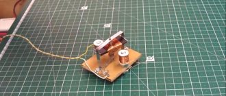
The assembled device looks like this:
When manufacturing a power unit (in the lower figure), the wires must be connected in such a way that there is a minimum of bending of those conductors through which large currents pass. We see that the manufacture of such a device requires certain professional knowledge and skills. Perhaps in some cases it makes sense to use a purchased device.
Assembly and inclusion
Connect the DC input power to CON2 and the output load to CON3. The PWM disable input is optional, if it is not required leave the connector disconnected and the output will be enabled.
The HEX file is ready to be programmed directly into the PIC12F683. The asm file contains the source code, which you can modify or simply view to see how it works. If you are going to change the code, we recommend downloading and installing Microchip MPLAB IDE, which allows you to easily edit, modify and program the PIC.
If you need to control the positive contact
In this case, we will need another mosfet transistor - P-channel. The circuit is similar, only the pull-up resistor is connected to the positive.
You will also need to invert the signal at the Arduino output, because when 5 volts are applied, the transistor will close, and when 0 volts is applied, it will open, which means that a PWM with a duty cycle of 30% will produce 70% power at the output of the circuit.
PWM on irf4905, power supply 5 v
It is worth making a reservation that such a circuit will only work with a power supply no higher than 5 volts , since in order to completely close the P-channel transistor it is necessary to pull its gate to the power positive, and the arduino is capable of delivering only 5 volts to the digital pin. This means that when powered at least slightly higher than the voltage supplied to the digital pin, the transistor will not completely close at the top of the PWM pulse and WILL HEAT VERY HEATED. It will also not be able to completely turn off the load.
If you need to control, for example, a 12-volt device, then the circuit will become a little more complicated. A so-called “swing arm” or field-effect transistor driver will be added. According to the classics, it is assembled on two and sometimes three transistors, but we have a slightly simpler option that works at low frequencies:
Arduino, PWM control via positive wire IRF4905