Briefly about the device
Structure of a pulse power supply.
Compared to a conventional power supply, the pulse generator has a rather complex circuit design. The mains voltage passes through the filter, is rectified and smoothed. The constant voltage is supplied to the inverter, where pulses with an amplitude of about 300 volts and a frequency of several kilohertz or tens of kilohertz are “cut” from it using transistor switches. The keys are controlled by a special circuit designed as a generator.
If the source is unregulated and unstabilized, then the generator simply generates pulses of a certain frequency. If stabilization and regulation of the output voltage is needed, this is done using pulse width modulation (PWR, PWM). The pulses follow at a constant frequency, and the voltage is regulated by changing their length. In the same way, you can limit the output current, as well as protect against overload or short circuit. For this purpose, adjustment (feedback) circuits are provided - permanent or with the possibility of online adjustment.
The pulses converted to the secondary winding are rectified in the usual way, pass through a smoothing filter and are supplied to the consumer. Due to the high conversion frequency, the dimensions of the pulse transformer are small. The capacitance (and size) of the smoothing capacitors in the output filter is also small - due to this, the pulse generator gains in weight and size indicators.
More details here: Description of operation and design of a switching power supply
METHODS FOR CHECKING TRANSFORMERS.
Alexander Stolovykh
In this article, the author introduces readers to several ways to test pulse, isolation and line transformers. The article provides a method for improving oscilloscopes S1-94, S1-112 and the like for more convenient diagnostics of transformers. When repairing TVs, VCRs and other electronic equipment, it is often necessary to check transformers. There are many methods that allow you to reject faulty transformers with a certain probability. This article discusses methods for testing transformers, switching power supplies, horizontal scan transformers of televisions and monitors, as well as horizontal scan transformers (TDKS).
METHOD 1 To check, you will need a sound generator with a frequency range of 20.100 kHz and an oscilloscope. To the primary winding of the transformer being tested through a capacitor with a capacity of 0.1. 1 µF supplies a sinusoidal signal with an amplitude of 5.10 V. The signal is observed on the secondary winding using an oscilloscope. If in any part of the frequency range it is possible to obtain an undistorted sinusoid, we can conclude that the transformer is working. If the sine wave signal is distorted, the transformer is faulty. The connection diagram is shown in Fig. 1, and the shape of the observed signals is in Fig. 2, respectively. METHOD 2 To test the transformer, connect a capacitor with a capacity of 0.01 in parallel to the primary winding. 1 µF and apply a signal with an amplitude of 5-10 V from an audio frequency signal generator to the winding. By changing the generator frequency, we try to cause resonance in the resulting parallel oscillatory circuit, monitoring the signal amplitude using an oscilloscope. If you short-circuit the secondary winding of a working transformer, the oscillations in the circuit will disappear. It follows from this that short-circuited turns disrupt resonance in the circuit. Therefore, if there are short-circuited turns in the transformer under test, we will not be able to achieve resonance at any frequency. The connection diagram is shown in Fig. 3. METHOD 3 The principle of testing a transformer is the same, only instead of a parallel circuit, a series circuit is used. If the transformer has short-circuited turns, at the resonance frequency a sharp breakdown of oscillations occurs, and it will be impossible to achieve resonance. The connection diagram is shown in Fig. 4. METHOD 4 The first three methods are more suitable for testing power transformers and isolation transformers, and the serviceability of TDKS transformers can only be assessed approximately. To check horizontal transformers, you can use the following method. We apply rectangular pulses with a frequency of 1.10 kHz of small amplitude to the collector winding of the transformer (you can use the output of the oscilloscope calibration signal). We connect the oscilloscope input there and draw a conclusion based on the resulting picture. On a working transformer, the amplitude of the resulting differentiated pulses should be no less than the amplitude of the original rectangular ones. If the TDKS has short-circuited turns, then we will see short differentiated pulses with an amplitude two or more times smaller than the original rectangular ones. This method is very rational, since it allows you to use only one measuring device when checking, but, unfortunately, not every oscilloscope has a generator output intended for calibration. In particular, such popular oscilloscopes as S1-94, S1-112 do not have a separate calibration generator. I propose to make a simple generator on a single chip and place it directly in the oscilloscope housing, which will help quickly and efficiently test horizontal transformers. The generator circuit is shown in Fig. 5. The assembled generator can be placed in any convenient place inside the oscilloscope, and the power can be supplied from a 12 V bus. To turn on the generator, it is convenient to use a dual toggle switch (P2T-1 -1 V), it is better to place it on the front panel of the device in a free place not far from oscilloscope input connector. . When the generator is turned on, power is supplied through a pair of contacts on the toggle switch, and another pair of contacts connects the output of the generator to the input of the oscilloscope. Thus, to check the transformer, it is enough to connect the transformer winding to the input of the oscilloscope using an ordinary signal wire. METHOD 5 This method allows you to check the TDKS for interturn short circuits and open circuits in the windings without using a generator. To check the transformer, disconnect the TDKS terminal from the power source (110...160 V). We connect the collector of the horizontal scanning output transistor with a jumper to the common wire. We load the power supply along the 110.160 V circuit with a 40.60 W, 220 V light bulb. We find a voltage of 10.30 V on the secondary windings of the power supply transformer and through a resistor with a resistance of approximately 10 Ohms we supply it to the disconnected terminal of the TDKS. Using an oscilloscope, we monitor the signal at the resistor. If there is an interturn short circuit in the transformer, the picture will look like a “dirty fluffy rectangle”, and almost all the voltage will drop across the resistor. If there are no short circuits, the rectangle will be clean, and the voltage drop across the resistor will be fractions of a volt. By monitoring the signal on the secondary windings, it is possible to determine their malfunction. If there is a rectangle, the windings are working, if not, they are broken. Next, we remove the 10 Ohm resistor and attach a load (0.2. 1.0 kOhm) to each secondary winding of the TDKS. If the output picture with the load practically repeats the input one, we can conclude that the TDKS is working properly, and feel free to return everything to its place. Thus, using one of the above methods, you can easily determine the malfunction of a suspicious transformer.
Read also: Crafts on a metal lathe
METHODS FOR CHECKING TRAN FORMERS
M. G. RYAZANOV
I want to share a simple and reliable (100%!) method for checking split transformers in TVs, monitors, etc. To do this, we use the collector winding of the transformer. We apply rectangular pulses of 1.10 kHz of small amplitude to it. I use the calibration signal output of the C1-114 oscilloscope for this. We connect the oscilloscope input there, and draw a conclusion based on the resulting picture. With a working transformer, the maximum amplitude range of the resulting differentiated pulses should be no less than the amplitude of the original rectangular ones. If the split transformer has short-circuited turns, then we will see short differentiated pulses with an amplitude two or more times less than the original, rectangular ones. With a little experience, this method can also determine the malfunction of transformers of network switching power supplies. The method works without soldering the transformer. Naturally, you need to make sure that there is no short circuit in the secondary circuits of the environment.
A very convenient and simple probe for checking TDKS and OS line coils on TVs.
Romanov. M., Lod, Israel.
I have been using it for 6-7 years, and during this time almost all faulty TDKS were defective with it. The reliability of diagnostics is confirmed by the practice of its use. The main indicator when checking a soldered TDKS is the sound heard in the piezoceramic emitter with a frequency of 15 kHz, which is easy to hear if the transformer or OS is working. When checking the TDKS, only the collector winding is connected. Details. Piezoceramic emitter (for example, from a Chinese alarm clock), KT315 transistors or similar, 1N4148 diodes. Resistors located in the collectors of transistors that include LEDs (R5, R8) will have to be selected based on the clear response of LED1 when connecting any conductor and LED2 only when connecting a working TDKS.
Using this device is very simple: connect the two ends of the collector winding of the transformer under test to points LX1, if the TDKS is working, LED1 lights up and a 15 kHz squeak is heard, if there is no squeak, the TDKS is faulty. The deflection system is also checked, only instead of a squeak, LED2 lights up. Any short-circuited turn or broken diode in the high-voltage winding of the line transformer or deflection system being tested disrupts the resonance, and the sound is absent or weakened to such an extent that it is barely audible.
Note: information from the TV Repair website in Russian
Where to start, how to find the right scheme
The best repair option is if there is a circuit diagram for a specific power supply. In reality, everything is somewhat more complicated. Manufacturers do not include circuit diagrams in the documentation for power supplies. You have to look for them on the Internet. The problem is that even well-known manufacturers are not enthusiastic about showing off their developments, and small companies from Southeast Asia do not have their own websites at all. We have to collect from the entire network what enthusiasts have found and posted. And if it is relatively easy to find a circuit for computer power supplies, then for pulse generators intended, for example, to power LED strips, the situation is more complicated.
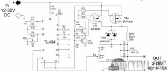
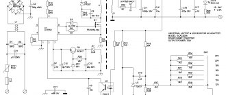
SMPS SKS-320.
Thus, for the SKS-320 power supply, when requesting a diagram, a well-known search engine produces only one adequate picture (obviously drawn by a volunteer from China). Using this device as an example, the troubleshooting algorithm will be described below.
Schematic diagram of the UPS SKS-320.
For other sources, the diagram may not be found at all. In this case, the best solution is to copy the circuit from the board yourself. This requires certain qualifications - you must, at a minimum, know what electronic components look like, and also have an approximate idea of the expected result. To do this, you need to know what circuit design the power supplies are made of. To make your work easier, you can mark the power paths on the board with a marker and number the elements (if they are not already numbered).
Another way is to find a similar circuit, which may not completely coincide with the real block, but this is better than nothing.
Basic faults of a switching power supply
External manifestations of a malfunction may be as follows:
- extraneous noise, smell of smoke, burnt insulation when turned on (at idle or under load);
- The switching power supply does not start when turned on - there is no power-on indication, there is no output voltage (or all voltages);
- one of the output voltages is missing (if the power supply has several channels);
- unstable output voltage;
- increased or decreased output voltage.
Separately, it is necessary to highlight a malfunction when the fan of a unit with forced cooling does not turn on. The problem itself does not affect performance, but in the near future it may lead to overheating and breakdown.
If the first problem on the list is observed, the power supply must be immediately de-energized and not connected to the 220 volt network until the problem is eliminated.
How can I check the UPS?
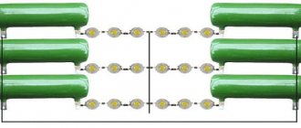
If in doubt, you can check the operation of the UPS. To do this, it must be turned on under load - some sources simply do not start at idle. As an equivalent, you can use car light bulbs if the unit is designed for an output voltage of 12 volts, or other incandescent light bulbs, connecting them in series and parallel to create the required load. If there are no suitable lamps, you can make up a load of resistors of the required resistance and required power.
A light bulb as a power supply load.
For a simple check of functionality, the current through the lamps must be at least 5..10% of the UPS rating. If the source is with forced cooling, you need to load it so that the current is at least half of the maximum allowable (or better, closer to the upper limit). This is necessary to force the temperature relay to operate to check that the fan is turned on.
Converter design
Before you begin directly checking a pulse transformer (IT), it is advisable to know how it works, understand the principle of operation and distinguish between existing types.
Such a pulse device is used not only as part of a power supply, it is used when constructing protection against short circuits in idle mode and as a stabilizing element. A pulse transformer is used to convert the magnitude of current and voltage without changing their shape. That is, it can change the amplitude and polarity of various types of pulses, coordinate various electronic cascades with each other, and create reliable and stable feedback. Therefore, the main requirement for it is to preserve the shape of the pulse.
This is achieved by reducing parasitic quantities, such as interturn capacitance and inductance, by using small cores, the arrangement of turns, and reducing the number of windings. The main characteristics of the transformer are: power and operating voltage. Structurally, the device can be made in the following form:
- rod - the magnetic circuit of such a transformer is made of U-shaped plates wrapped around windings;
- armored - W-shaped plates are used, and the windings are located in coils, forming a kind of armor;
- toroidal - its appearance resembles the geometric figure of a torus, while it does not have coils, and the winding is wound on the core;
- mixed (armored rod) - assembled from four coils and a combined type magnetic circuit.
The magnetic core in the transformer is made of electrical steel plates, except for the toroidal form, in which it is made of rolled or ferromagnetic material. The coil frames are placed on insulators, and only copper wires are used. The thickness of the plates is selected depending on the frequency.
The arrangement of the windings can be made in a spiral, conical and cylindrical form. A feature of the first type is the use not of wire, but of a wide thin foil tape. Secondly, they are made with different insulation thicknesses, which affects the voltage between the primary and secondary windings. The third type is a structure with wire wound around a rod in a spiral.
Power supply repair technique
Those who are involved in restoring the functionality of electronic equipment know that 90+ percent of repairs come down to troubleshooting . Replacing a found faulty element in most cases takes little time and does not require special skills.
The second point is that impulse generators of the same type have structural weaknesses that lead to characteristic problems, but in general, troubleshooting is a creative process, and it is literally impossible to give step-by-step instructions. But it is quite possible to present a general search methodology, although one must understand that it is worthless without sufficient qualifications and the availability of instruments. At a minimum, you will need a multimeter and an oscilloscope.
Visually, you can only identify swollen and leaking oxide capacitors . Even if charred elements are visible during inspection, replacing them may not yield anything - the cause of burnout may be other components.
Swollen oxide capacitors are detected by visual inspection.
Troubleshooting
Diagnosing a faulty device must begin with analysis. For first estimates, knowledge of the power supply block diagram and the external manifestation of the malfunction is sufficient.
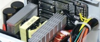
Location of the main elements on the SKS-320 SMPS board.
If, when turned on, the UPS shows no signs of life at all (does not heat up, no voltage indication, no subtle squeak is heard, no output voltage) or its output voltage is less than the rated voltage, then the first thing to check is the serviceability of the fuse (item 1 in the figure) . If it is OK, you need to check the voltage level on capacitor C5 (item 2, point 1 in the diagram). It should be about 300 volts. If there is no voltage, a malfunction of the high-voltage rectifier can be assumed. But first you need to make sure that ~220 volts reaches it. If not, you need to look for where it disappears.
Next you need to check the operation of the PWM controller. In this case, it is implemented on the TL494 chip (item 3). The functionality and numbering of its pins are summarized in the table.
| Function | Marking | Pin numbering | Pin numbering | Marking | Function | |
| Non-inverting input of error amplifier 1 | IN1 | 1 | 16 | IN2 | Non-inverting input of error amplifier 2 | |
| Amplifier 1 inverting input | | 2 | 15 | Amplifier 2 inverting input | ||
| Feedback | FB | 3 | 14 | Vref | Stabilized voltage +5.0 volts (current up to 10 mA) | |
| Setting the pause time between pulses (Dead time) | DTC | 4 | 13 | OTS | Mode (push-pull/single-stroke) | |
| Frequency setting circuit capacity | C | 5 | 12 | VCC | Power pin | |
| Frequency setting circuit resistance | R | 6 | 11 | C2 | Collector of output transistor 2 | |
| 0 volt | GND | 7 | 10 | E1 | Output transistor emitter 1 | |
| Output transistor collector 1 | C1 | 8 | 9 | E2 | Emitter of output transistor 2 | |
You need to check with an oscilloscope that there are antiphase pulses at outputs 8 and 11 of the microcircuit. If they are not there, you need to check the presence of supply voltage at pin 12 (item 4) of the TL494.
The shape of the pulses at pins 1 and 11 of the microcircuit.
If it is absent, you need to find the reason for the loss. If there is power, but there are no pulses, you need to check the wiring of the microcircuit.
If there is generation, you need to use an oscilloscope to verify the presence of pulses on the primary winding of transformer T1 (points 3,4 in the figure). Their amplitude should be about 150 volts. If not, you need to check the serviceability of the divider capacitors C5, C6. An ESR meter is very useful for this.
Measuring capacitor parameters using an ESR meter.
If one or both capacitors have poor insulation quality, they must be replaced. If you don’t have an ESR meter, you can measure the voltage at point 2. There should be about 150 volts - half of the voltage at point 1. If it differs significantly, this also indicates a malfunction of one or two capacitors. If everything is in order there, check the serviceability of transistors Q4 , Q5 (item 5), transformer T2 (item 7), transistors Q1 , Q2 (item 6), as well as all diodes in the driver circuit and the inverter output stage.
If everything is in order, and there are pulses on the primary winding, but not on the secondary, you need to check the transformer T1 (pos. 8), checking the integrity of all windings.
If there are pulses on the secondary winding, you need to check the rectifier elements - the secondary rectifier assembly D3 (item 9). If it is completely faulty, then there will be no output voltage. If only one diode fails, the output voltage will be lower.
Also, the cause of high and low voltage may be a malfunction of the feedback circuits. In the circuit, the voltage feedback is implemented on the operational amplifier U1 . There is nothing on the board that looks like an op-amp, therefore, there is a slight discrepancy between the modification of the power supply and the found circuit. You need to be prepared for this, and you need to cope with such a situation yourself, having understood the features of the circuitry. Current feedback is organized through inductor L1 (item 10) and a 680 Ohm shunt. By measuring the temperature on this throttle, the automatic fan switching is organized; the sensor is installed in close proximity to the throttle. You can check whether the cooler turns on when there is no corresponding load by heating the sensor using, for example, a hair dryer. If the fan does not start, you need to look for a fault.
Checking the fuel assembly for interturn and open circuit without a generator.
M. G. RYAZANOV.
If there is a suspicion of a fuel assembly and there is an oscilloscope, then: cut off the fuel assembly leg from the power supply (+115 V, +160 V, etc.); On the secondary power supplies we find output B at 10.30 and connect via R-10 Ohm to the cut off terminal of the fuel assembly; Let's admire the oscillogram:
a) at R=10 Ohm. If the interturn short circuit is a dirty fluffy “rectangle”, almost all the voltage sits on it, if there is no interturn circuit, then a fraction of a volt;
b) on the secondary windings - if there is something missing somewhere, then there is a break;
c) remove R=10 Ohm, attach a load (0.2. 1.0 kOhm) to each secondary winding of the fuel assembly, if the output picture with the load practically repeats the input - the fuel assembly is alive and well; we return everything to its place.
Alexander Omelyanenko
The author believes that methods for testing pulse transformers with low-level signals without desoldering from the circuit are unreliable. It offers two simple methods for testing transformers in near-operational conditions. Of course, their dismantling is required, but the reliability of the test results is guaranteed! Pulse transformers of power supplies and line scanners most often fail due to overheating of the windings. When power switches break down, the current in the winding increases sharply, which leads to its local heating with subsequent damage to the insulation of the winding wire. More often this happens in small-sized transformers wound with thin wire, for example, in the power supplies of modern VCRs, video players and line transformers (TDKS) of televisions. As a result of overheating of the winding wire, interturn short circuits occur, sharply reducing the quality factor of the transformer, which disrupts the operating mode of the self-oscillator of a switching power supply (SMPS) or the horizontal scan cascade. Checking pulse transformers of power supplies and TDKS is a fairly relevant topic; many methods for detecting interturn short circuits have been described. The results of testing pulse transformers by measuring the resonant frequency, inductance or winding quality factor are unreliable. The resonant frequency of a transformer, in particular, depends on the number of turns, the capacitance between the layers of windings, the properties of the core material and the height of the gap. Interturn short circuits do not eliminate resonance, but only increase the resonant frequency and reduce the quality factor of the coil. The shape of the test sinusoidal voltage is not distorted by short-circuited windings, and it is generally unreasonable to use rectangular pulses due to the occurrence of shock excitation pulses. There are also devices based on this principle, but they are ineffective. Core saturation can affect the shape of the pulse, but in this case a high-power generator is needed. Apparently, for these reasons, the effectiveness of the known methods is very low, and the test results are unreliable. Below we offer simple reliable methods for testing pulse transformers in a mode close to operating. The horizontal scan output stage of the TV or its switching power supply (SMPS) is used as a signal generator. The proposed methods make it possible to safely detect points of breakdown of the insulation of the TDKS body, the so-called “fistulas”. To check using the first method, you need a working TV, the horizontal scan of which is used as a generator. The TDKS being tested must be dismantled and its filament winding connected to the filament voltage terminals on the kinescope board, as shown in Fig. 1. For the second method, a working SMPS is used as a generator, it can even be from a TV that is being repaired. To check the TDKS, the winding intended for connecting the line transistor is connected to the secondary winding of the SMPS transformer, designed to generate a voltage of 110. 140 V (Fig. 2).
Checked TDKS Fig. 1. Connection of the tested TDKS through the filament winding
In both cases, the TDKS turns out to be in a mode close to the operating one, and the criterion for its serviceability can be considered the appearance at the anode terminal of a high voltage capable of “breaking through” 2.3 cm of air space. To make a spark gap, you can use a wire with two alligator clips. One “crocodile” is connected to the negative terminal of the anode winding, and the second is hung on a “suction cup”, where a spark gap is formed. The presence of short-circuited turns is easily determined by the overload of the generator (line scan or SMPS) and the absence of discharges in the high-voltage circuit. Suspicious SMPS transformers can be checked using the second method, by connecting a winding intended for a power switch to the generator output. A sign of the presence of short-circuited turns in the tested transformer is an overload of the SMPS, generation failure and protection activation. Finally, a reminder: when working with high voltages, remember the safety rules!
“Repair of electronic equipment” No. 1, 2003
When is the best time to contact the service?
If you do not have the minimum required equipment, it is better to contact a specialized organization that repairs switching power supplies. Without a minimum of equipment, an undertaking is doomed to failure in 99% of cases. Also, you should not hope to repair the device if there is no circuit diagram (at least in any form) and with insufficient qualifications. There is little point in undertaking repairs (and even taking them to service) in a situation where some of the elements have burned out. They can be replaced, but the insulating properties of the section of the board covered with soot will be far from those declared by the manufacturer, and you won’t have to wait long for a new malfunction.
For clarity, we recommend a series of thematic videos.
But in general, repairing impulse generators is a thankless task and not very profitable. They are not so expensive that you need to start a painstaking troubleshooting. But if there is no other choice or the process itself is enjoyable, then the review materials will be useful.