Parameter calculations
On a simple transformer the primary winding has 440 turns for 220 volts. It turns out 1 volt for every two turns. Formula for counting turns by voltage:
It will be interesting➡ Tesla coil (Transformer) self-assembly on your own
N = 40-60 / S, where S is the cross-sectional area of the core in cm2. The constant 40-60 depends on the quality of the core metal. Let's make a calculation for installing the windings on the magnetic circuit. In our case, the transformer has a window 53 mm in height and 19 mm in width. The frame will be textolite. Two cheeks at the bottom and top 53 - 1.5 x 2 = 50 mm, frame 19 - 1.5 = 17.5 mm, window size 50 x 17.5 mm.
- The winding of a simple high voltage transformer is 2.18 x 450 = 981 turns.
- Low voltage for filament 2.18 x 5 = 11 turns.
- Low voltage filament 2.18 x 6.3 = 14 turns.
We calculate the required diameter of the wires. The power of the transformer core with your own hands is 170 watts in size. On the network winding the current is 170 / 220 = 0.78 amperes. Current density is 2 amperes per mm2, standard wire diameter according to the table is 0.72 mm. The factory winding is made of 0.5 wire, the factory saved money on this.
The assembled magnetic core, together with the components and connecting elements, forms the core of the transformer. The part on which the windings are wound is the rod. The area of the system intended to complete the circuit and not carrying any turns of the circuit is called the yoke. The arrangement of the rods in space serves to divide the system into the following types.
Types of arrangement of rods.
How to connect
Connecting transformers in parallel operation is allowed only if all the listed conditions are met. It is possible to operate devices with different groups of windings:
- in groups with a difference of 4 hours (120 degrees), a circular rearrangement of the windings is performed;
- groups with a difference of 6 hours (180 degrees), for example 0, 4, 8 and 6, 10, 2, are connected after changing the places of the beginning and end of the winding of one of the transformers;
- in odd groups, two phases on the high and low voltage windings are swapped.
In all cases, the windings are re-phased.
All installation and switching work is carried out in the absence of high voltage.
Manufacturing of windings
The coil is placed on a wooden block with the dimensions of the magnetic core. A hole for the winding rod is pre-drilled in it. This part is inserted into the machine, and the winding manufacturing process begins:
- 2 layers of varnished fabric are wound on the reel;
- one end of the wire is fixed on the cheek and the handle of the machine begins to slowly rotate;
- the coils must be laid tightly, isolating each wound layer from the adjacent one with varnished cloth;
- after the primary winding coil is wound, the wire is cut and its second end is fixed on the cheek next to the first.
Insulating tubes are put on both terminals, and the outside of the winding is covered with insulation. The secondary winding coil is wound in the same sequence.
Repair and service
A transformer is a complex piece of equipment. Periodic maintenance and repair will be required. It is recommended to entrust this work to professionals. Only a person with appropriate training has the right to carry out such work.
With an increased heating rate and the presence of noise, it is necessary to rewind the transformer circuits. This procedure can only be performed by an unqualified specialist with a minimum level of knowledge in the field of electrical engineering.
The device has a magnetic drive. It is common to coils. The first circuit is responsible for reducing, and the second circuit is responsible for increasing electricity in the network. Inspection of the transformer is carried out using a certain technology.
Examination
First, a visual inspection of the block is carried out. If overheating is observed during operation, deformations, irregularities, and swelling of the insulation appear on the surface. If the inspection does not reveal any deviations, you need to find the input and output of the device. The first of them is connected to the first coil. This is where a magnetic field appears when electricity is supplied. The output is connected to the secondary winding.
The output signal is filtered. This indicator needs to be measured. The collapsible parts of the housing structure are removed. You need to gain access to the microcircuits. This will allow you to measure the voltage with a multimeter. In this case, you will need to take into account the nominal indicators. If the measurement result is less than 80% of the value specified by the manufacturer, the primary circuit is not functioning correctly.
The first coil is disconnected from the device. It no longer receives electricity. Then the secondary circuit is checked. If there is no filtering, power from the measuring device is used. If there is no normal voltage in the system, the equipment requires repair.
After checking, if the component elements are in good condition, the structure is assembled in the reverse order. If necessary, the unit is repaired.
Design and principle of operation
The appearance of a typical current transformer is shown in Figure 1. A characteristic feature of these models is the presence of a dielectric housing. Case shapes can be different - from rectangular to cylindrical. Some designs do not have pass-through bars in the center of the body. Instead, a hole was made to wrap around the wire, which serves as the primary winding.
Read also: Headdress for a fur coat (93 photos)
Rice. 1. Current transformer
Dielectric materials are selected depending on the voltage for which the device is intended and on its operating conditions. To service industrial energy systems, powerful CTs with cylindrical ceramic housings are manufactured (see Fig. 2).
Rice. 2. Industrial ceramic current transformer
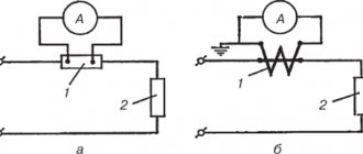
A feature of the transformer is the mandatory presence of a load element (resistance) in the secondary winding (see Fig. 3). The resistor is necessary in order to prevent operation in mode without secondary loads. The operation of a current transformer with unloaded secondary windings is unacceptable due to strong heating (up to destruction) of the magnetic circuit.
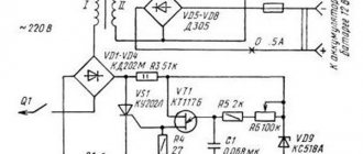
Rice. 3. Schematic diagram of a current transformer
Maintenance and repair
Step-up transformers are technically complex devices, so self-correction of breakdowns is highly discouraged .
The only thing that can be done with your own hands is rewinding the windings of the device .
Let us take as an example the type that uses multiple windings. This unit contains a magnetic core, which is common to all three inductors. As a rule, one coil is a step-down coil and the other a step-up coil in this device.
It would be a good idea to learn the procedure for checking transformers, which will help you avoid potential problems in the future. Let's look at the whole procedure step by step :
- First you need to inspect the entire block. As a rule, overheating of the system provokes the appearance of some bulges or irregularities, which indicate deformation of some parts.
- We determine the input and output of the device. The first circuit must be connected to the first coil of the device, where the magnetic field itself is formed. The second part, which acts as a receiver of energy from the magnetic field, must be connected to the secondary winding.
- Then you need to determine the filtering of the output signal. It is noteworthy that it is identical for the diodes and capacitors on the second coil of the device.
- Next, you need to remove some parts of the case so that you have full access to the device’s microcircuits. This is necessary so that voltage readings can be determined using a multimeter.
- If the obtained indicators are significantly less than expected (less than 80% of optimal), then the probable cause of the breakdown lies in the entire circuit that connects around the primary winding. To correct the causes, you should disconnect the first coil from the electricity supply to it.
- Next you need to check the secondary output. If there is no filtering, then you need to use power from a multimeter. If you notice that the optimal voltage is not achieved, then the reason may be in the transformer itself, or in the output terminals.
In general, it is better to entrust all these manipulations to the appropriate specialist , who will not only correctly disassemble and assemble the device, but also check the voltage frequency indicators in individual sections of the primary and secondary winding circuits.
What is idle mode
One of the most used electrical devices is the transformer. This equipment is used to change the magnitude of electrical voltage. Let's consider the features of the transformer no-load mode, taking into account the rules for determining characteristics for various types of devices.
The transformer consists of primary and secondary windings located on the core. When voltage is applied to the input coil, a magnetic field is formed, inducing a current in the output winding. The difference in characteristics is achieved due to the different number of turns in the input and output coils.
The idle mode is understood as the state of the device in which, when an alternating current is supplied to the input coil, the output coil is in an open state. This situation is typical for a unit connected to the mains, provided that the load to the output circuit has not yet been turned on.
Short circuit mode
During the experiment you can find:
- no-load electric current (measured with an ammeter) - usually its value is small, no more than 0.1 of the rated current of the first winding;
- power lost in the magnetic circuit of the device (or in other words, losses in steel);
- voltage transformation indicator - approximately equal to the value in the primary circuit divided by that for the secondary (both values are data from voltmeters);
- Based on the results of measurements of current, power and voltage of the primary electrical circuit, the power factor can be calculated: the power is divided by the product of two other quantities.
Manufacturing workflow of coil frames
Transformer coil.
When using a round core, it is first wrapped with tape insulation and then the wire begins to be wound directly onto it, distributing the required number of turns throughout the entire ring.
After the winding of the primary winding is completed, it is covered with 3-4 layers of varnished cloth and then the turns of its secondary part begin to be wound on top. When using conventional magnetic cores, the coil frame is made as follows:
- a sleeve pattern is made with cuffs on the sides of the ends;
- cheeks are cut out of cardboard;
- roll the coil body along the marked lines into a small box and seal it;
- put the upper parts (cheeks) on the sleeve and, bending the flaps, glue it.
After this, the wire is covered with tape insulation, having previously brought the ends of the windings out.
Device principle
When considering how a voltage-increasing transformer works, you need to delve into the basic principles of the design. The basis for the operation of a transformer is the mechanism of electromagnetic induction. The metal core is in an insulating environment. The circuit includes two coils. The number of windings is not the same. Coils with more turns in the first circuit than in the second can increase the indicator.
AC voltage is supplied to the primary circuit. For example, this is a current in the network of 110 (100) V. A magnetic field appears. Its strength increases with the correct ratio of windings in the core. When electricity passes through the second winding in the step-up transformer, a current with a certain indicator appears. For example, an indicator of the characteristics of a 220 V network is provided.
In this case, the frequency remains the same. To supply direct current to the power supply line, a converter is installed in the circuit. This device can be used in boost-type equipment. The device is capable of working not only to change voltage, but also frequency. Certain equipment is powered by direct current.
Where did he come from
At the beginning of the 19th century, scientists studied the properties of the magnetic field. And it was experimentally shown that an alternating magnetic field is capable of creating a current: it was recorded by instruments on a conductor. However, for a long time no one measured its value.
By the middle of the same century, the properties of ferromagnets and the parameters of the magnetic field were studied, and even a prototype of a transformer appeared - the Ruhmkorff coil. Finally, in 1876, the Russian scientist P. N. Yablochkov patented the world's first rod transformer.
A little later, the first transformers with a closed core began to be produced in England, which became the prototype of almost all modern devices of this type. All further work was carried out in the direction of improvement, and they were based on studying the operational properties of this device. Thus, cores made of laminated material and oil cooling were introduced. In the USSR, the spread of transformers went along with the electrification of the entire country, from the late 20s of the last century.
Operating principle of a step-up transformer
A step-up transformer works on the same principle as a regular transformer. Step-up transformers draw lower voltage and provide higher voltage. Their work is based on Faraday's laws and rotation coefficient theory.
Inside a step-up transformer, current flows due to the input voltage. The flow of current induces a magnetic flux around the windings, and this flux passes through the core of the transformer.
The voltage in the secondary windings is induced by the secondary winding.
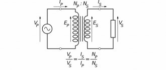
The next operating principle is the rotation coefficient. The gear ratio is expressed as the ratio of the number of turns of the primary winding to the turns ratio of the secondary winding. It is also described as the ratio of input voltage to output voltage.
Turnover ratio = Nprimary/Nsecondary =Vprimary/Vsecondary ———————- (i)
Or, Vsecondary = Vprimary * (Nsecondary / Nprimary) ——————— (ii)
Here Nprimary = number of turns of the primary winding.
Nsecondary = Number of turns of the secondary winding
Vprimary = primary side voltage
Vsecondary = Secondary side voltage
Using the marked equation (ii), we attempt to calculate the secondary stress. It is clear that the input voltage is constant. Now by changing the transformation ratio we can get the desired output voltage. A step-up transformer is used to create a higher voltage output. This is why the ratio (Nsecondary / Nprimary) is set to greater than 1.
Now from the equations we can notice that the secondary N will be larger as opposed to the step down transformer. Therefore, a step-up transformer has a larger number of turns in its secondary windings.
Learn how a transformer works. Click here for navigation!
Functions and operation of transformers
In electronics, transformers are indispensable devices. However, for them to work most effectively, it is necessary to have a good understanding of what the transformer is stepping down or stepping up. Depending on the needs, they increase or, conversely, decrease the potential in circuits with alternating current.
With the advent of different transformer devices, it became possible to deliver electricity over significant distances. Losses on power line wires are noticeably reduced when the alternating voltage increases and the current decreases. This occurs along the entire length of the conductors connecting the power plant with connected consumers. At each end of such lines, the voltages are reduced to a safe level, facilitating the operation of the equipment used.
Which transformer is called step-up and which is called step-down, and what is the difference between them?
The short answer is that a device that produces a higher potential, compared to the input, is considered a booster. If the reverse process occurs, and the potential at the output is less than at the input, such a device will be a step-down device. In the first case, the secondary winding has a larger number of turns than the primary, and in the second, on the contrary, a secondary winding with fewer turns is used. This is how they differ radically from each other.
Can a step-down transformer be used as a step-up transformer?
Yes, you can. Since to change the functions it is enough to change the connection diagram of the windings with the potential source and the load. Accordingly, the functionality of the step-down transformer will change.
In practice, in order to improve the efficiency of the device, the inductance of all windings is calculated for the exact operating values of current and voltage. These indicators must be maintained in their original state when the step-up and step-down transformer change their functions to the opposite.
How to determine which winding belongs to one or another
Structurally, transformers are made according to such a principle that it is impossible to immediately determine their differences, that is, which wires are called and actually are the primary, and which of them are the secondary winding. Therefore, to avoid confusion, markings are used. The symbol “H” is provided for the high-voltage winding; in step-down devices it serves as the primary winding, and in step-up devices it serves as the secondary winding. Low voltage windings are marked with an “X”.
In order to understand the features, differences and operating principle of each of these devices, they should be considered in more detail.
Bell transformer - parameters and application
Bell transformers have one purpose - to reduce the network voltage to a level suitable for a home or a specific device. This is so that the bell can be placed outside, such as on a fence, where high humidity or the possibility of splashing increases the risk of electric shock. At low voltages this is not dangerous.
The parameters of bell transformers do not change much, but the choice is often severely limited by technical problems.
- Output voltage and output current . Their level is determined by checking the call requirements. Bell transformers with voltages greater than 8 V are relatively rarely used these days. 12 V is the level needed for large, complex doorbells or intercoms. In both cases, this is an absolutely safe voltage. Many bell-type transformers have multiple terminals, combinations of which produce different output voltages (for example, 4, 8, or 12 V);
- Installation method . Many older electrical installations still have a few or dozens of transformers installed. Technically they are usually effective, although efficiency, safety and aesthetics leave much to be desired. These transformers were installed directly on the wall, but today this solution is practically not used. Currently, developers prefer to install transformers for the T-35 bus. A transformer on a DIN rail can be installed without additional holes in the structure and is more versatile;
- Safety . In this regard, the differences are small, since overheating and overload protection are standard, but in each case it is worth paying attention to the offer of individual manufacturers.
Step-down transformers
For certain devices used in everyday life, a voltage of 220V is unnecessary - it is recommended to use step-down transformers to connect them (220 to 15 volts or 220 to 10 volts).
The advantages of using these mini-transformers for the home include:
- protection against electric shock and fire (especially important in bathhouses, bathrooms and other rooms with high humidity);
- saving energy consumption (low-voltage lighting devices consume several times less energy than conventional ones);
- extending the service life of devices.
Chargers for phones, laptops and other gadgets already have built-in transformers, but when installing low-voltage lighting using LED and halogen lamps, you need to independently install devices to reduce the voltage.
Advantages and disadvantages of cores
- Stacked ones are more often used for constructing magnetic cores with an arbitrary cross-section, limited only by the width of the plates. Voltage transformation devices with a square cross-section have the best parameters. The disadvantage of this type of core is the need to tightly tighten the plates, the low fill factor of the coil space, as well as increased dissipation of the magnetic field of the device.
- Twisted cores are much easier to assemble than type-type ones. The entire W-type core consists of four parts, while the U-shaped type has only two parts in its design. The technical characteristics of such a transformer are much better than those of a type-setting transformer. The disadvantages include the need for a minimum gap between parts. With physical impact, the plates of the parts can peel off, and in the future it is very difficult to achieve a tight fit.
- Toroidal cores have the shape of a ring, which is made of transformer iron tape. Such cores have the best technical characteristics and almost complete elimination of magnetic field dissipation. The disadvantage is the difficulty of winding, especially wires with a large cross-section.
In W-type transformers, all windings are usually made on the central rod. In a U-shaped device, the secondary winding can be wound on one rod, and the primary winding on another. Especially often, there are design solutions when windings divided in half are wound on both rods, and then connected to each other in series. At the same time, the wire consumption for the transformer is significantly reduced and the technical characteristics of the device are improved.
Other types
In accordance with the performance characteristics, the presented equipment differs in several ways. Depending on the number of circuits, there are single-phase (domestic) and three-phase (industrial) designs.
Various substances are used as a cooling system. There are oil and dry varieties. In the first case, the equipment costs less. Oil is a flammable substance. When used, high-quality protection against accidents is provided. Dry units are filled with a non-flammable substance. They are more expensive, but the requirements for their installation are fair.
Coolant circulation in the system can be forced or natural. There are designs that combine these methods. The variety of types allows everyone to choose the optimal type of device.
Operation
To understand what voltage-increasing transformers are, you need to understand the principle of operation. The equipment is manufactured for power plants whose design schemes belong to the pass-through category.
A step-up transformer at power plants is used to provide populated areas and other objects with current with certain technical indicators. Without a converter, the high voltage gradually decreases along its path. The end consumer would receive insufficient electricity. At the final power plant in the circuit, thanks to this installation, electricity of the appropriate value is received. The consumer receives a network voltage of up to 220 V. Industrial networks are provided with up to 380 V.
A diagram showing the operation of a transformer in a line includes several elements. The generator at the power plant produces 12 kV electricity. It is supplied through wires to step-up substations. A transformer apparatus is installed here, designed to increase the indicator in the line to 400 kV.
From the substation, electricity enters the high-voltage line. Next, the energy enters the step-down substation. Here it drops to 12 kV.
Transformers with a reverse operating principle direct the current to the low-voltage transmission line. At the end, another step-down unit is installed. From it, electricity with an indicator of 220 V is supplied to houses, apartments, etc.
Varieties
The category of boosting types of equipment includes a number of devices that differ in design, purpose, and technical characteristics:
- Autotransformer. It has one combined winding.
- Power. The most common type among devices that increase voltage.
- Anti-resonant. Has a closed design. Due to their special operating principle, they have compact dimensions.
- Grounded. The windings are connected in a star or zigzag pattern.
- Peak transformers. Separate direct and alternating current.
- Household. The improvement in the characteristics of electricity during the operation of a transformer is carried out in a small range. They help eliminate interference in the household network, protect equipment from surges, low and high electricity.
The presented designs differ in power and technical characteristics.
Transformer types
As with any technical device, step-up transformers can be of various types, differing in power ratings, scope of use, etc.
Let's consider each type of this device in more detail:
- The autotransformer has only one winding with a pair of end terminals. As a rule, these are single-phase type transformers, in which there are primary and secondary coils.
- Current transformers have a larger number of windings compared to the previous type. In addition, the design of such devices uses a magnetic core, resistors and optical sensors responsible for adjusting the voltage frequency.
- A power-type unit is a special device that transmits current between circuits through the process of electromagnetic induction.
- The anti-resonance type unit is a cast device that has an almost completely closed structure. Both three-phase and single-phase devices are available for sale. In many ways, these devices are similar to power units, but have more compact dimensions.
- Grounded devices differ from others in the special structure of the windings, which are connected to each other by a zigzag or star.
- Peak transformers are used to separate AC and DC current. These devices have become quite widespread in computer technologies and radio communications.
- Home separation devices are used as a transmitter of electricity from an AC source to the device itself. Household devices with a power of 220 volts are used as a protective measure against the effects of electric current and to prevent interference in the operation of various devices.
Step-up voltage transformers
Voltage transformation is present everywhere in every area of our lives and activities. The voltage generated at the power plant is increased to several kilovolts in order to be transmitted with minimal losses through power lines over many thousands of kilometers. And then it is again reduced at transformer substations to our usual values of 380/220 volts.
Step-up transformers are not used to stabilize voltage in cases where its value in the network is constantly changing. For home use, only stabilizers are used.
Let's look at the principle of operation of a voltage transformer in more detail, without plunging into unnecessary complications.
Types of products
Now we will describe some of these converters and the features of their design.
Power converter
This is a device that operates in networks and serves to increase or decrease voltage during power transmission. In large power systems, the voltage generated by the power plant is first increased to several hundred volts (or even megavolts) to reduce transmission losses. Then step-down transformers are installed in the regions, and thus the electricity reaches your apartment in several steps. The last transformer in front of your house steps down the voltage from 10 kV to 220 V.
Since our transmission lines are three-phase, with a shift of 120 degrees, there are three coils in your yard booth, and the voltage between the secondary windings of any two of them is 400 (in fact, with the loads turned on - 380) volts. And between any of the phases and the neutral - 220. That’s why on the door of the substation it says “10 kV/400 V/220 V”. Such products are produced in rod and armor types.
Also, a step-down transformer is found in a number of household appliances, where 220 V is converted to 12.
Instrument transformers
They can be found in large substations and power supply plants. They are used to measure the parameters of high-voltage networks, since it is simply impossible to connect measuring equipment at high voltage. Fundamentally, they do not differ from power ones, it’s all about the operating mode and connection diagram.
For measurement accuracy, such transformers are connected to the network in such a way that they have the least possible impact on the measured indicators.
Since these devices are designed to measure relevant parameters, they are subject to certain accuracy class requirements. The measurements take place on a scale, and if the deviations in the secondary winding are small, then in the primary they will be many times higher - that is, they need to be multiplied by the transformation ratio. Therefore, such transformers are subject to regular inspections.
Pulse options
Designed to convert voltage and current that have a pulsed (not sinusoidal) change graph. The task of such an element in the circuit is to transmit a pulse without distorting its shape, which is quite difficult if you remember about parasitic inductances and capacitances, as well as the properties of the core. Therefore, when calculating such transformers, special attention is paid to the latter - it must have good inductance and at the same time not cause “smearing” of the signal.
Speaking about pulse electrical transformers, one cannot fail to mention peak transformers, whose task is to convert a sinusoidal signal into a pulse one. To achieve this, two methods are used:
- a large resistance is placed in series in the primary winding;
- A magnetic shunt is placed between the windings.
In both cases, the emphasis is on changing the characteristics of the magnetic flux, the change in which determines the shape of the signal in the secondary winding.
Welding devices
This is a type of step-down converter, and the reason for the design differences of this converter from the others is its operating mode. If a simple transformer operates under load, then a welding transformer operates in a short circuit. Accordingly, it must withstand the high currents that flow through its secondary winding. Of course, they try to minimize the current by placing the windings further away from each other, but the very essence of the arc welding process requires current. Therefore, the cross-section of the wire in the secondary winding is large, and the cables that welders carry around are well insulated.
Autotransformers
These are not classic converters: they do not have a separation into primary and secondary windings in the literal sense of the word, they are directly connected to each other.
Changing the voltage is achieved by changing the number of turns. Most often, such devices have a third terminal, and in some cases they are adjustable.
Autotransformers have found their application where a large transformation ratio is not needed, for example, in stabilizers. Within certain limits, they allow you to adjust the voltage to the standard required by the load.
Currently, they are often found in laboratories and, oddly enough, on the railway. Such a scheme ensures uninterrupted power supply over long distances with a minimum of losses.
These are not all varieties of this converter, both in design and purpose. You can write about the use of a transformer for a long time: it has taken its strong place in the electrical power industry and radio electronics for a long time. In the meantime, we’ll better understand its structure.
Which transformer is called a step-up transformer?
A step-up transformer is an ordinary transformer (see the purpose and principle of operation of a transformer) that increases the voltage value of an electric current. On the primary winding it is lower, and on the secondary winding it is higher. Thus, the voltage at the output of the device is higher and, due to a certain number of turns of the winding and cross-section, has the desired value.
The principle of operation of a step-up transformer is the value of K (transformation ratio).
When K>1 the transformer is a step-down transformer, and when K is a step-up transformer circuit
Application of step-up transformers
The devices are installed in electrical lines and power supplies of consumer points. According to the Joule-Lenz law, as the current increases, heat is released, which heats the wire. To transmit energy over long linear distances, the voltage is increased and the currents are decreased. When reaching the consumer, the power is reduced, since for safety reasons it would be necessary to use massive insulation.
At the beginning of the chain, a step-up transformer is installed, and at the receiving point the indicators are reduced. Such combinations are used repeatedly along power lines, achieving favorable conditions for transporting electricity and creating acceptable values for the consumer.
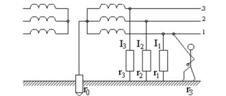
Due to the presence of three phases in the network, three-phase units are used for energy transformation. Sometimes a group is used in which the devices are combined into a star model, with a common conducting rod.
Although the efficiency of high-power units reaches almost one hundred percent, a lot of heat is still generated. A typical 1 GW power plant transformer produces several megawatts. To reduce this phenomenon, a cooling system has been developed in the form of a tank containing non-flammable liquid or transformer oil and a strong air heat distribution device. Cooling is often water-based; the dry principle is used at low power.
Step-up toroidal transformer
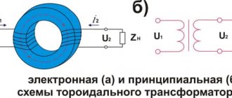
As you understand, when we say “toroidal transformer,” we usually mean a network single-phase transformer, power or measuring, step-up or step-down, whose toroidal core is equipped with two or more windings.
A toroidal transformer works in principle the same way as transformers with other forms of cores: it lowers or increases the voltage, increases or decreases the current - it converts electricity. But a toroidal transformer, with the same transmitted power, is smaller in size and lighter in weight, that is, has better economic indicators.
The main feature of a toroidal transformer is the small total volume of the device, reaching up to half in comparison with other types of magnetic cores.
The laminated core is twice as large in volume as a toroidal strip core with the same overall power.
Therefore, toroidal transformers are more convenient to install and connect, and it is no longer so important whether we are talking about internal or external installation.
Any specialist will say that the toroidal core shape is ideal for a transformer for several reasons:
- firstly, saving materials in production,
- secondly, the windings evenly fill the entire core, distributed over its entire surface, leaving no unused spaces,
- thirdly, since the windings are shorter, the efficiency of toroidal transformers is higher due to the lower resistance of the winding wires.
Winding cooling is another important factor.
The windings are effectively cooled by being arranged in a toroidal shape, hence the current density can be higher.
Losses in the iron are minimal and the magnetizing current is much lower. As a result, the thermal load capacity of the toroidal transformer turns out to be very high.
Energy savings are another plus in favor of a toroidal transformer.
Approximately 30% more energy is saved at full load, and approximately 80% at idle, compared to laminated magnetic cores of other forms. The dissipation index of toroidal transformers is 5 times less than that of armored and rod transformers, so they can be safely used with sensitive electronic equipment.
With a power of a toroidal transformer up to a kilowatt, it is so light and compact that for installation it is enough to use a metal pressure washer and a bolt. All the consumer needs to do is select a suitable transformer based on load current and primary and secondary voltages. When manufacturing a transformer at the factory, the cross-sectional area of the core, the area of the window, the diameters of the winding wires are calculated, and the optimal dimensions of the magnetic circuit are selected, taking into account the permissible induction in it.
Why are voltage-increasing transformers installed near power plants?
Any conductor has its own resistance and therefore heat losses inevitably occur in power lines due to heating of the conductor . The amount of heating is proportional to the square of the current in the circuit, so by increasing the voltage to hundreds of kilovolts, we, according to Ohm’s law, lower the current, and therefore reduce heat losses and the size of power line conductors, saving materials and costs.
- See the principle of operation of transformers in the transmission of electrical energy over a distance
Video: Step-up transformer
Tips for choosing
Before purchasing a voltage stabilizer, you need to decide whether it is needed or not, but for preventive purposes it is still worth installing, since the voltage in electrical networks often varies.
When choosing a mini-transformer, the following characteristics are taken into account:
- Number of phases.
- Output power.
- Weight of the device.
- Transformer dimensions.
- Operational life.
- Operating voltage range.
- Speed of reaction to power surges.
The load of specific devices must be clarified. Single-phase transformers are purchased for low-power household appliances, three-phase stabilizers are purchased for a large number of devices that require load distribution.
One of the most popular and sought-after transformers is the Resanta ASN, a single-phase digital stabilizer with an affordable price of 2,600 rubles. This transformer is mounted on the wall.
A more expensive and reliable model is the Shtil stabilizer. Its approximate cost is 4,000 rubles. The Shtil stabilizer is optimally suited for protecting electronic equipment and household appliances at alternating voltage.
Technological connection to electrical networks
- Required power calculator - an approximate calculation of the need for electrical power to submit an application for technological connection;
- Cost calculator - approximate calculation of the cost of technological connection to electrical networks, depending on the type of connection (existing or new);
- Connection stages - a detailed description of the main stages required for technological connection to electrical networks;
- Answers of JSC Lenenergo to frequently asked questions on the technological connection of additional capacity or new capacity and the conclusion of an energy supply agreement.