Types of power supplies
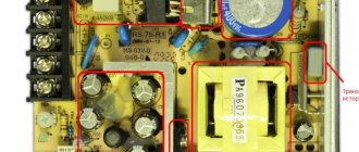
Today, switching voltage sources are widely used. Compared to traditional transformer circuits, they have a significant advantage in energy efficiency and weight and size indicators. It is believed that at load currents of more than 5 amperes they have undeniable preferences. But they also have disadvantages - for example, the generation of RF interference into the supply network and into the load. And the main obstacle to home assembly is the complexity of the circuits and the need for special skills to make winding parts. Therefore, it is better for a semi-skilled home craftsman to start making a power supply according to the usual principle with a network step-down transformer.
Distinctive features of three-phase equipment
The operating principle of the device, assembled according to an electrical circuit for a rectifier powered by three mains phases, is based on the presence of a small ripple in the output voltage. The waves overlap each other in the process, preventing the voltage from dropping to zero.
The welding installation is constructed by including semiconductors behind the transformer windings in phases. The terminals are connected, resulting in a single output. Through such a bridge, waves divided in two are passed, forming a rapid pulsation, but with less force. In such a design, you will need a zero output, and the transformer is connected to the power supply according to a special circuit.
Craftsmen know in practice that the highest quality work is obtained with the use of devices operating on direct current, providing an arc with stable combustion and a durable seam. In order to obtain the necessary parameters, despite the growth of technological discoveries and the emergence of innovations in instrument making, craftsmen with their own hands produce and still use the simplest rectifiers.
Transformer power supply circuit
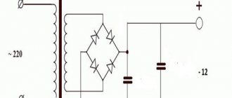
Schematic diagram of the power supply.
The circuit of a 12 volt power supply operating from a 220 V network consists of the following components:
- A step-down transformer . It consists of iron, primary and secondary (there may be several) windings. Without going deeply into the principle of operation, it should be noted that the output voltage depends on the ratio of the turns of the primary (n1) and secondary (n2) windings. To obtain 12 volts, the secondary winding must contain 220/12 = 18.3 times fewer turns than the primary.
- Rectifier. Most often it is performed in the form of a full-wave circuit (diode bridge). Converts alternating voltage into pulsating voltage. The current passes through the load twice in one direction per period.
Operation of a full-wave rectifier. - Filter .
Converts pulsating voltage into constant voltage. It charges when voltage is applied and discharges during pauses. It consists of a high-capacity oxide capacitor, in parallel with which a ceramic capacitor with a capacity of about 1 μF is often connected. To understand the need for this additional element, we must remember that the oxide capacitor is designed in the form of strips of foil rolled into a roll. This roll has parasitic inductance, which significantly degrades the quality of filtering high-frequency interference. To do this, an additional HF pulse short-circuit capacitor is turned on. Equivalent filter circuit with oxide and additional capacitors. - Stabilizer . May be missing. Schemes of simple but effective units are discussed below.
The following sections discuss the procedure for selecting and calculating each element of a 12-volt DC voltage source.
Types of devices, their features
DIY welding rectifier
A homemade welding rectifier is needed to effectively power a household or industrial structure with small volumes of work and work cycles.
In industry, more powerful equipment is used; operations with it do not create pauses during welding.
During this period, the hot parts cool down, the speed of the procedure decreases, which does not interfere with home appliances.
These products consist of elements:
- transformer
- capacitor unit
- rectifier
When starting to create a welding device, the master needs to decide on the direction of work and its dimensions.
The following depends on the volume of production and the number of connections:
- selection of the necessary electrodes
- system parameters
- material characteristic
The assembler, having selected the necessary diagram and materials, and having assembled the device step by step, will achieve the necessary indicators in the system.
Transformer selection
There are two ways to obtain a suitable transformer. Independent production of a step-down block and selection of a suitable one in the factory. In any case, you need to keep in mind:
- at the output of the step-down winding of the transformer, when measuring the voltage, the voltmeter will show the effective voltage (1.4 times less than the amplitude);
- on the filter capacitor without load, the constant voltage will be approximately equal to the amplitude voltage (they say that the voltage on the capacitor “rises” by 1.4 times);
- if there is no stabilizer, then under load the voltage on the capacitor will drop depending on the current;
- For the stabilizer to operate, a certain excess of the input voltage over the output voltage is required; their ratio limits the efficiency of the power supply as a whole.
From the last two points it follows that for normal operation of the power supply, the transformer voltage must exceed 12 V.
Why remake the device?
Now you know that the question “So which current is better: alternating or constant?” has no answer. Devices on a break and devices on a permanent basis are two different phenomena with their own advantages and disadvantages. And ideally, it is better to have in your arsenal universal equipment that can cook with both direct and alternating current.
There are such devices on sale, but they are incomparably expensive. If you are a professional, then it makes sense to buy such a device. But if you are an amateur and cook a couple of times a year at your dacha or in the garage, then it is better to purchase a transformer device and modify it a little. A transformer operating on alternating current can be equipped with the ability to switch to direct current. This way you will get an inexpensive universal device, which will also be powerful and reliable.
Self-winding transformer
The complete calculation and manufacture of a homemade power transformer is complex, time-consuming, and requires tools and skills. Therefore, a simplified path will be considered - selecting a block suitable for hardware and converting it to 12 V.
If there is a ready-made transformer, but there is no wiring diagram for it, you need to call its windings with a tester. The winding with the highest resistance will most likely be the mains winding. The remaining windings must be removed.
Next, you need to measure the thickness of the iron set b and the width of the central plate a and multiply them. The cross-sectional area of the core will be S=a*b (in sq.cm). It determines the power of the transformer P=
. Next, the maximum current in amperes is calculated, which can be removed from a winding with a voltage of 12 volts: I = P/12.
Determination of core area.
Next, the number of turns per volt is calculated using the formula n=50/S. For 12 volts, you need to wind 12*n turns with a margin of about 20% for losses in copper and on the stabilizer. And if it is not there, then the voltage drop under load. And the last step is to select the cross-section of the winding wire according to the schedule for a current density of 2-3 mA/sq.mm.
Selecting copper wire.
For example, there is a transformer with a 220 V primary winding with a set of iron 3.5 cm thick and a middle tongue width of 2.5 cm. This means S = 2.5 * 3.5 = 8.75 and the power of the transformer
=3 W (approx.) Then the maximum possible current at 12 volts is I=P/U=3/12=0.25 A. For winding, you can choose a wire with a diameter of 0.35..0.4 sq. mm. For 1 volt there are 50/8.75 = 5.7 turns, you need to wind 12 * 5.7 = 33 turns. Taking into account the reserve - about 40 turns.
Selection of a finished transformer
If you have a ready-made transformer with a secondary winding suitable for current and voltage, you can try to select a ready-made one. For example, in the TPP series there are suitable products with a voltage of secondary windings close to 12 volts.
| Transformer | Designation of secondary winding terminals | Voltage, V | Allowable current, A |
| Chamber of Commerce and Industry48 | 11-12, 13-14, 15-16, 17-18 | 13,8 | 0,27 |
| TPP209 | 11-12, 13-15 | 11,5 | 0,0236 |
| TPP216 | 11-12, 13-14, 15-16, 17-18 | 11,5 | 0,072 |
The advantage of this solution is minimal labor intensity and reliability of factory execution. Minus - the transformer contains other windings, the overall power is also designed for their load. Therefore, in terms of weight and size, such a transformer will lose.
Multi-station welding rectifiers - counting work stations
Three-phase networks also allow you to connect multi-station welding machines. The power of a household, single-phase 220 Volt network is simply not enough for such a powerful load. To ensure the operation of all posts, the rectifiers have a rigid external Volt-Amp characteristic. Each welding lead has its own rheostat and choke for individual adjustment.
Their advantage is lower equipment maintenance costs, and their scope of application is welding sites with a large volume of work. These could be construction sites where complex metal structures are being installed or shipyards. That is, the area of application is industry, but not everyday life. The number of connected welding stations for a multi-station rectifier will be calculated using the formula:
- n= Ivyp/k* Iload;
- where Ivypr is the rated current for which the rectifier is designed;
- Iload – current required for one post;
- k is a coefficient that takes into account the simultaneous operation of posts; for mechanical welding it is taken within the range of 0.5-0.7.
Selecting diodes and making a rectifier
Diodes in the rectifier are selected according to three parameters:
- highest permissible forward voltage;
- highest reverse voltage;
- highest operating current.
According to the first two parameters, 90 percent of available semiconductor devices are suitable for operation in a 12-volt circuit; the choice is mainly made based on the maximum long-term permissible current. The design of the diode body and the method of manufacturing the rectifier also depend on this parameter.
If the load current does not exceed 1 A, you can use foreign and domestic one-ampere diodes:
- 1N4001-1N4007;
- HER101-HER108;
- KD258 (“droplet”);
- KD212 and others.
KD105 (KD106) devices are designed for lower currents (up to 0.3 A). All of the listed diodes can be mounted either vertically or horizontally on a printed circuit board or circuit board, or simply on pins. They don't need radiators.
Diode bridge made of low-power elements.
If large operating currents are needed, then other diodes must be used (KD213, KD202, KD203, etc.). These devices are designed for operation on heat sinks; without them they will withstand no more than 10% of the maximum rated current. Therefore, you need to select ready-made heat sinks or make them yourself from copper or aluminum.
Another diode bridge design.
It is also convenient to use ready-made bridge diode assemblies KTs405, KVRS or similar. There is no need to assemble them - just apply an alternating voltage to the corresponding terminals and remove the constant one.
Assembly of KVRS3510.
What is good about the device and what hinders it?
How to convert an AC welding machine into a DC welding machine - the necessary semiconductor circuit with a rectifier device will answer this question for the master:
- The three-phase system has the best performance; it allows you to use network power up to 380 V.
- Such equipment is used where a large continuous process is needed in order to weld large steel parts without interruption during this time period. With the help of these powerful devices you can produce gates, containers, and any utility metal structures.
- Such a tool will be useful mainly not in a private household, but for small businesses and the sale of manufactured products. This is because these are bulky and heavy structures, unlike devices with fewer phases, they require additional installations to move the device.
In such a system, the transformer is capable of reducing weight, but you need to be able to wind its core yourself or buy a ready-made one with the necessary parameters.
Capacitor capacity
The capacitance of the capacitor depends on the load and the ripples it tolerates. To accurately calculate capacity, there are formulas and online calculators that can be found on the Internet. For practice, you can focus on the numbers:
- at low load currents (tens of milliamps), the capacitance should be 100..200 µF;
- at currents up to 500 mA, a capacitor of 470..560 μF is needed;
- up to 1 A – 1000..1500 µF.
For higher currents, the capacitance increases proportionally. The general approach is that the larger the capacitor, the better. Its capacity can be increased to any limit, limited only by size and cost. In terms of voltage, you need to take a capacitor with a serious margin. So, for a 12-volt rectifier it is better to take a 25-volt element than a 16-volt one.
These arguments are valid for unstabilized sources. For a power supply with a stabilizer, the capacity can be reduced significantly.
Output voltage stabilization
A stabilizer at the output of the power supply is not always needed. So, if you plan to use a power supply in conjunction with sound-reproducing equipment, then the output must have a stable voltage. And if the load is a heating element, the stabilizer is clearly unnecessary. To power an LED strip, you can do without the most complex power supply module, but on the other hand, a stable voltage ensures independence of the brightness of the glow during changes in the network and extends the life of the LED lamp.
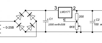
If the decision to install a stabilizer has been made, then the easiest way is to assemble it on a specialized microcircuit LM7812 (KR142EN5A). The connection circuit is simple and does not require adjustment.
Stabilizer for 7812.
The input of such a stabilizer can be supplied with voltage from 15 to 35 volts. A capacitor C1 with a capacity of at least 0.33 μF must be installed at the input, and at least 0.1 μF at the output. The capacitor of the filter unit usually acts as C1 if the length of the connecting wires does not exceed 7 cm. If this length cannot be maintained, then the installation of a separate element will be required.
The 7812 chip has protection against overheating and short circuit. But it does not like reversing the polarity at the input and applying external voltage to the output - its life time in such situations is calculated in seconds.
Important! For load currents above 100 mA, installing an integrated stabilizer on the heat sink is mandatory!
Operating principle of a single-phase bridge circuit
The process of alternating current flow can be represented as a wave oscillating at a certain frequency. This procedure is very fast, which can be imagined as at one specific moment, a current passes first in one direction and then in the other.
In welding, specialists ensure that these movements are carried out unilaterally:
- A semiconductor is soldered into the secondary winding of the transformer; it carries out electrical transmission in the desired direction, which is direct current. Since alternating current has frequencies, its waves will create pauses that are unacceptable in the work process.
- In the circuit, the electrical components are soldered in the opposite direction with respect to each other, then the electron flow will flow in the opposite direction.
- If you create a circuit with pairs of elements directed towards each other, you will get a flow of waves oscillating from zero to maximum. This limit is calculated on the possibility of a secondary transformer winding.
- In the same way, fluctuations are obtained that decrease to a minimum, from the moment of which a new rise begins. In this case, a plus pole voltage is generated, and its minus is located in the transformer winding.
- This circuit is used with an output device in place, so as not to disassemble the winding; it can be created by winding it yourself. This design is famous for its efficiency in relation to the number of semiconductor elements.
- Dividing the winding into several sections allows you to use only part of it.
- The most convenient and applicable for electrical engineers is the bridge rectifier structure. A similar plan consists of a square with semiconductors on the sides. Some of its corners output direct current, others show the voltage output from the transformer.
This example has the advantage that it does not require creating a lead from the second winding, but it will require a lot of semiconductor gates. Welding will be with low power; electrodes of special sizes are selected for them, and parts with limited parameters are welded. It should be taken into account that the parallel connection of a capacitor device reduces wave vibrations during operation of the welding machine.
Increasing the output current of the stabilizer
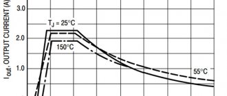
The above circuit allows you to load the stabilizer with a current of up to 1.5 A. If this is not enough, you can power the unit with an additional transistor.
Circuit with an NPN structure transistor
External NPN transistor.
This circuit is recommended by the developers and is included in the datasheet for the chip. The output current should not exceed the maximum collector current of the transistor, which must be equipped with a heat sink.
Circuit with pnp transistor
If there is no semiconductor triode of the npn structure, then you can power the stabilizer with a semiconductor triode pnp.
External PNP transistor.
A silicon low-power VD diode increases the 7812's output voltage by 0.6 V and compensates for the voltage drop across the transistor's emitter junction.
Parametric stabilizer
If for some reason an integrated stabilizer is not available, you can make a unit on a zener diode. It is necessary to select a zener diode with a stabilization voltage of 12 V and designed for the corresponding load current. The highest current for some 12-volt domestic and imported zener diodes is indicated in the table.
| Zener diode type | D814G | D815D | KS620A | 1N4742A | BZV55C12 | 1N5242B |
| Load current | 5 mA | 0.5 A | 50 mA | 25 mA | 5 mA | 40 mA |
| Stabilization voltage | 12 volts | |||||
Circuit diagram of a simple parametric stabilizer.
The resistor value is calculated using the formula:
R= (Uin min-Ust)/(In max+Ist min), where:
- Uin min – minimum input unstabilized voltage (must be at least 1.4 Ust), volts;
- Ust – zener diode stabilization voltage (reference value), volts;
- In max – highest load current;
- Ist min – minimum stabilization current (reference value).
If a zener diode for the required voltage is not available, it can be made up of two connected in series. In this case, the total voltage should be 12 V (for example, D815A at 5.6 volts plus D815B at 6.8 volts will give 12.4 V).
Important! You cannot connect zener diodes (even of the same type) in parallel “to increase the stabilization current!”
Zener diodes are not connected in parallel.
You can power up the parametric stabilizer in the same way - by turning on an external transistor.
Powerful stabilizer circuit.
For a powerful transistor, a radiator must be provided. The supply voltage in this case will be less than Ust of the zener diode by 0.6 V. If necessary, the output voltage can be adjusted upward by turning on a silicon diode (or chain of diodes). Each element in the chain will increase Uout by approximately 0.6 V.
Stabilizer circuit with zener diode and diode.
Output voltage regulation
If the power supply voltage needs to be regulated from zero, then the optimal circuit would be a parametric stabilizer with the addition of a variable resistor.
Smooth voltage regulation.
A 1 kOhm resistor connected between the base of the transistor and the common wire will protect the triode from failure if the potentiometer motor circuit breaks. When you rotate the variable resistor knob, the voltage at the base of the transistor will change from 0 to Ust of the zener diode with a lag of approximately 0.6 volts. It must be taken into account that the parameters of the node will be worse due to the use of a potentiometer - the presence of a moving contact (even of good quality) will inevitably reduce the voltage stability at the base of the transistor.
Device layout
After all the components have been selected, or there is a clear idea of what they will be, you can begin to assemble the device. It is also important to understand what the future body of the device will be like. You can choose a ready-made one, or you can make it yourself if you have the materials and skills.
There are no special rules for the layout of components inside the housing. But it is advisable to arrange the nodes so that they are connected by conductors in series, as in the diagram, and over the shortest distance. It is better to place the output terminals on the side opposite the network cable. It is better to mount the power switch and fuse on the back wall of the device. To rationally use the inter-body space, some of the units can be installed vertically, but it is better to fix the diode bridge horizontally. When mounted vertically, convection currents of hot air from the lower diodes will flow around the upper elements and additionally heat them.
For those who don’t understand, watch the video: Simple DIY power supply.
Assembling a fixed supply DC power supply is not difficult. An average craftsman can do this; only basic knowledge of electrical engineering and minimal installation skills are needed.
How to make a straightener with your own hands?
If the craftsman has the necessary components, it is quite possible to make a homemade welding rectifier. Provided that all recommendations of specialists are followed, it is guaranteed to provide the process of manual arc welding with direct current, but it will be necessary to use a coated electrode.
It is also permissible to use wire without coating, but only if you have extensive experience in welding matters. For an inexperienced welder, it will be almost impossible to cope with it.
Diode bridge for welding machine.
Coating when melting the electrode prevents the penetration of air components into the molten metal of the welded joint. Without it, contact of molten metal with nitrogen and oxygen will reduce the strength properties of the seam, making it brittle and porous.
First you will need to select or wind up a step-down transformer with your own hands with the required parameters. Assemble the transformer before connecting the diode bridge.
If you choose to manufacture the device yourself, it is important to correctly calculate its elements, including:
- magnetic circuit parameters;
- current number of turns;
- cross-sectional dimensions of busbars and wires.
On a note! Calculations for the manufacture of transformers are carried out using a unified methodology, so this task does not present any difficulties even for an inexperienced welder with school knowledge of electricity.
The work cannot be done without LEDs: they are needed as current conductors in one single direction. The simplest diode rectifier, created using a bridge circuit, is mounted on a radiator for the purpose of heat exchange and cooling.
Powerful diodes for a welding machine, like the VD-200, emit a fairly large amount of thermal energy during operation. To ensure a falling current characteristic, a choke will need to be connected in series to the circuit.
Active variable resistance in such a circuit will provide the welder with the ability to smoothly regulate the welding current. Next, one pole needs to be connected to the welded wire, and the second to the work object.
An electrolytic capacitor in the circuit is needed as a smoothing filter to reduce ripple.
It is not difficult to wind the rheostat on your own, but for such a task you will need a ceramic core and nickel or nichrome wire. The actual wire diameter will be determined by the amount of adjustable current in the welding operation.
The calculation of the rheostat resistance must be carried out taking into account the specific resistance of the electrode, its cross-section and total length.
Electrical circuit for welding with a diode bridge.
The current adjustment step for welding depends on the diameter of the turns. If you correctly assemble the listed parts into a single unit, the welding process will be accompanied by direct current. It would not be superfluous to install a resistor that prevents short circuits during operation.
It can occur when the wire touches metal without igniting the arc. If at this time there is no resistance on the capacitor, it will instantly discharge, a click will occur, the electrode will collapse or stick to the metal.
If you have a resistor, you can smooth out the discharges on the capacitor and make ignition of the electrode easier and softer. Making a device for rectifying weld current with your own hands will allow you to create the most accurate and durable welds. .
