Almost all automated systems contain a device such as a limit switch, which is responsible for turning them off when the moving part reaches a certain point. In lighting control systems, limit switches are used as sensors.
When programmed circumstances arise, they generate a signal.
- Inductive proximity sensors
What are limit switches
Limit switches are electrical devices designed to open and close a working circuit. They are mounted on moving mechanisms to limit their movement within specified boundaries. The functions that these devices perform are identical to a standard switch.
The filling of the limit switches is enclosed in a durable housing, most often metal. All its elements are optimized for easy fastening and easy orientation in space. Bright, different-colored LEDs allow you to control the power supply and sensor response. Two pairs of contacts, most often found in the limit switch, make it possible to monitor the state of its connection.
If the signal is not followed by a signal return when the pair is closed, this indicates a fault in the cable leading to the switch. After the sensor is triggered, it is possible to use an open pair of contacts to pass the signal.
Operating principle of an inductive sensor
The inductive sensor is discrete. The signal at its output appears when metal is present in a given zone.
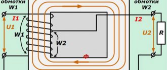
The proximity sensor is based on a generator with an inductor. Hence the name. When metal appears in the electromagnetic field of the coil, this field changes dramatically, which affects the operation of the circuit.
Induction sensor field. The metal plate changes the resonant frequency of the oscillatory circuit
And the circuit containing the comparator outputs a signal to a key transistor or relay. No metal - no signal.
Inductive npn sensor circuit. A functional diagram is shown, which shows: a generator with an oscillating circuit, a threshold device (comparator), an NPN output transistor, protective zener diodes and diodes
Most of the pictures in the article are not mine; at the end you can download the sources.
Types of limit switches
There are three main groups of limit switches: mechanical, non-contact, magnetic. The main function of all these devices is to automatically disconnect the working mechanism the moment its moving part reaches the set position. These switches serve not only to open a circuit, but also to connect it.
The operation of the circuit in the end sensors is coordinated in two ways: by direct action on the moving contacts and by positional control of them. In the first case they are called contact, in the second - non-contact. An example of contact limit switches are sensors responsible for closing car doors.
The photo shows the design of a track-type limit switch. Its main components are: cover (1), base (2), contacts (3), roller (4), lever (5), sealing strip (6)
Sensors of this type can not only turn mechanisms on and off, but also establish the position of the object being monitored. These include sensors that determine the fuel level. The signal for their operation is a change in resistance corresponding to a certain level of liquid.
The disadvantage of contact sensors in the presence of mechanical moving parts is a relatively short service life due to ineffective protection from moisture and dust. The advantage is simple design, installation and operation. Contactless switches are much more reliably protected from external influences. Their resource is also longer.
Purpose
The inductive sensor is designed to control the movement of the working element without direct contact with it. The main areas of application for it are machine tools, precision medical devices, process automation systems, measurement and control of product shape. In accordance with the provisions of clause 2.1.1.1 of GOST R 50030.5.2-99, this is a sensor that creates an electromagnetic field in the sensitivity area and has a semiconductor switch.
The scope of application of inductive sensors is largely determined by their high reliability and resistance to external factors. Their readings and operation are not affected by many environmental factors: moisture, condensation, accumulation of dust and dirt, ingress of solid particles. Such features are provided by their design and design data.
Mechanical type limit switches
The control of limit switches of this type can be roller or lever. They are triggered as soon as the control mechanism in the form of a wheel, button or lever experiences mechanical impact. In this case, the position of the contacts changes - they can close or open. The process is accompanied by a signal - control or warning.
Most often, limit switches have two contacts - open and closed. There are single end devices, but they are rare. In any case, there are contacts in each case, and a working diagram with their numbers is shown on the panel.
The design of roller VCs provides for switching off by pressing the actuator on a button in the form of a small rod. Since it is connected to dynamic contacts, at the moment of contact the supply circuit opens.
The difference between lever switches is that their movable contacts are connected to a small lever by means of a rod or a rod. The action occurs when the actuator presses this lever.
The photo shows a mechanical limit microswitch KW4-3Z-3 with a pressure bar. It differs from the standard one in the stroke of the working element. It is used in CNC machines and 3D printers
In addition to standard end devices, there are microswitches. They work on the same principle, but their adjustment during installation requires greater precision due to the small stroke. To increase the working stroke, they resort to such a technique as including an intermediate element in the circuit - a lever with a roller.
This type of switches is used both in production and at home. A large number of control units are used in the elevator design. Among them is a switch in the form of a sensor that limits the minimum and maximum height of the elevator, signals a rope break, gives a signal to open the door and performs many other actions. There are microswitches on the doors of many apartments that turn on the light in the room when it is opened.
Features of automotive limit switches
In automobiles, such mechanical end sensors are included in alarm and lighting circuits. Their feature is the presence of one input with a positive potential connected to it. The housing is the negative terminal, pressed against a metal element on the car body that is free of paint.
This element is connected to the vehicle ground by a cable. The main condition is that the switch should not come into contact with a wet surface. Connect the end sensors when installing a car alarm using a diagram. Their outputs can be installed both on the doors and in the interior on lighting fixtures.
To turn it on when the door is opened, and turn it off when it closes, a short circuit to positive is performed. If there is illumination of the interior ceiling and doors, a block of limit switches is used, which performs various functions. As a result of the block being triggered, important sensors are blocked when attempting to open the locks.
Features of contactless limit switches
One of the varieties of limit switches is their non-contact modification (BVK). The communication of the devices is configured to trigger when a specific object enters the sensitivity zone.
These limit switches are adjusted to a specific material and a given size. As soon as an object with such parameters enters the sensitive zone, the amplitude of the generator oscillations is transformed
There are no moving parts in the device itself, and there is no mechanical contact between the object of influence and the switch element configured for it. The BVK consists of the following parts:
- sensitive element;
- power key;
- component that analyzes the signal.
The distance at which the device begins to operate is set based on the modification of the sensor and the requirements of the process. The exclusion of both moving and rubbing elements significantly increases the reliability of these devices. Contactless sensors, or proximity sensors as they are also called, have extensive functionality. There are two categories - switches and position sensors.
The first task of the BVK is to detect the position of an object. In addition, the sensor performs counting, positioning, separation, and sorting of objects. It can control speed, movement, calculate rotation angle, correct skew and perform many other actions.
Sensitive devices are used in industry, in the transport industry, as an element of automation, and in oil refining. Based on the principle of detecting approaching objects, BKVs are distinguished between inductive, capacitive, optical, and ultrasonic.
Inductive proximity sensors
They are tuned to materials both metallic and amorphous. Among those reacting to metal there are magnetic and ferromagnetic options. Inside the sensor there is a core - metal or magnetized.
The switch can receive power with a wide range of voltage values - from 10V at direct current, alternating - from 264 V. The output signal is created at 0.2 A in the case of direct current and 0.5 A in alternating current
If we describe the design of such a sensor in more detail, it consists of a converter that includes a copper coil located in a ferrite cup. Its functions include redirecting the vector of electromagnetic lines to the front part of the switch. The oscillator in the circuit can be either with a fixed negative resistance or any other type.
The magnetic field lines are oriented perpendicular to the direction of the current flowing through the turns of the magnetized core. The alternating force field is caused by the alternating voltage at the core inputs. The next important component is the signal conditioner, which creates hysteresis and the range of action of the control signal. It includes a trigger controlled detector.
The diagram shows an inductive motion switch in action. Its main element is an inductor driven by a generator
The key to the operation of an inductive limit switch is the changes that occur when an object approaches or moves away. As soon as the voltage threshold exceeds the permissible value, the sensor is activated by connecting a trigger that opens the key.
Capacitive limit switches, non-contact
After the object appears, the vibrator circuit of the capacitive device is started, and time parameters are set. As the object approaches the sensor, the capacity of the latter increases, and the frequency generated by the multivibrator decreases. As soon as the frequency threshold is exceeded, the device will turn off. The block diagram of a capacitive sensor is similar to an inductive device: both models contain a generator and a detector.
The principle of operation of a capacitive type limit switch is based on changing the capacitance of the receiving element - the capacitor. In such sensors, the switching operation begins when dielectric and metal objects enter their field
In addition to the generator that generates the electric field, their design includes such basic parts as a demodulator. It acts as a converter of the amplitude of high-frequency oscillations with a simultaneous change in voltage. The next important component is the trigger, which is responsible for a certain signal level, switching and hysteresis dependence.
To increase the input signal to a set value, an amplifier is included in the capacitive switch circuit. The LED indicator monitors the settings and operation of the device. An element such as a compound protects the switch from moisture and solid particles. A plastic or brass body protects everything inside it from mechanical damage. The kit also includes mounting hardware.
The switching element in this device is located on a capacitor and is a plate that interacts with a vibrator. The role of the threshold element is performed by a comparator connected to the vibrator. The latter, in turn, is connected to a frequency and voltage converter.
Capacitive limit switches react to solid materials, powdery, liquid, both electrically conductive and non-conductive
The difference between capacitive models and inductive ones is that the former react to air humidity and changes in density. The latter are insensitive to such influences.
Ultrasonic switch design
The design of ultrasonic limit switches provides for the presence of quartz sound emitters that form pulsed waves with a length of 100 - 500 kHz, and a receiver whose settings correspond to a certain frequency. When the amplitude of sound waves changes as a result of maneuvers of a moving object, the BVK microswitch records the new values and, based on this, controls the output signals.
The operating principle of ultrasonic sensors is based on the change in time during which a sound wave travels from the sensor to the controlled object. The detection distance of such devices is quite large - up to 10 m. Their big advantage is that they can detect an object of any shape and color that reflects sound.
The operation of this ultrasonic sensor is based on a simple principle: as soon as a signal is received on one of its legs, the other receives a pulse with a length equal to the distance to the object
Such sensors are used to detect objects with a flat surface occupying a perpendicular position relative to the detection center line. Inaccuracies in their work can cause:
- Sudden, high-power air currents that strengthen or weaken the wave.
- Sudden change in temperature. With a large amount of heat emitted by an object, the speed of the propagated waves changes.
- Deviation from the vertical of the angle between the horizontal plane of the object and the axis of the sensor. If this error exceeds 10⁰, the sensor does not operate.
- Angular outlines of the object. In this case, its identification is very difficult.
Vibrations propagate in solid, gaseous, liquid media, and the speed depends on the relevant parameters. Ultrasonic sensors have no moving parts, so there is no relationship between the number of cycles and the service life of the device. They are characterized by increased resistance to all kinds of external influences.
Contactless optical switches
BKVs of this type control objects that both block radiation and reflect it. When an object enters the space between the switch and the light source, the sensor interrupts the light output. The element responsible for this action can be a relay or semiconductor. The response radius extends up to 150 m.
This is a photo of an optical type end sensor. It determines the positions of the extreme points of movement of moving parts in 3D printers and CNC machines
Proximity sensors operate in a wide temperature range - from -60 to +150⁰С. They can withstand pressures of about 500 atm and can be used in aggressive environments and even in conditions of increased explosion hazard.
Application of inductive sensor
Inductive proximity sensors are widely used in industrial automation to determine the position of a particular part of the mechanism. The signal from the sensor output can be input to a controller, frequency converter, relay, starter, and so on. The only condition is matching the current and voltage.
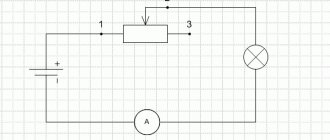
Operation of an inductive sensor. The flag moves to the right, and when it reaches the sensor's sensitivity zone, the sensor is triggered.
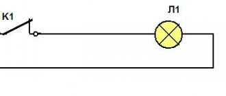
By the way, sensor manufacturers warn that it is not recommended to connect an incandescent light bulb directly to the sensor output. I have already written about the reasons - the current when the lamp is turned on significantly exceeds the rated one.
Magnetic limit switches
This type of switches, which are also called float switches or reed switches, is gradually replacing mechanical models. Their contacts change position when they are at some distance from the magnet. In this case, a signal is sent to the control circuit.
The reed switch contains one or two contacts made of a special material - a ferromagnet. The magnetic limit switch is small in size. It is placed in a housing made of plastic or glass, and mounted into an electrical circuit at its break.
The contacts in such a switch can be open, closed, or switchable. In devices of the first type, the contact closes when triggered. Normally closed contacts open in similar circumstances, and switched contacts behave according to the situation.
The choice of model depends on specific circumstances. Reed switches are used in the design of sliding gates. With their help, the structure is stopped when it reaches the extreme position when opening or closing.
Some float models are used as part of a security alarm at the entrance to a house. When the door is closed, the circuit is closed due to the influence of the magnetic field on the limit switch. The opening of the door provokes the movement of the magnet and the opening of the contact, causing the alarm to turn on.
When installing magnets, take into account their polarity. If installed incorrectly, they will not perform their intended functions.
The fact that there is no mechanical contact in this design is its advantage, which increases longevity. They are distinguished by the simplest structure, based on the interaction of magnetically controlled contacts with a conventional magnet.
Newspaper of ZAO MPO Elektromontazh
Newspaper "MPO ELEKTROMONTAZH" May 2013
In the room
Accent
- MPO Elektromontazh at the Mosbuild-2013 exhibition
Let there be light
- LED spotlights General lighting
From distant travels
- Milan and Hannover are nearby
Famous brand
- Unica sockets and switches
- Dospel fans
New assortment
- Modul installation products
- Magnetic contactors KT
- Don't look down on capacitors...
- Inductive proximity switches
Tool
- NWS fitting tools
- Taste of tension
Cable management
- Magic cambrics
- Repairing a power cable?
The past of great discoveries
- James C. Maxwell
Happy holiday
- Military power of light
Newspaper archive by year
All articles by newspaper section
Rules for connecting limit switches
Although limit switches themselves are designed quite simply, they are used in equipment with complex electrical circuits. Consequently, their connection must be carried out by specialists and strictly according to the schematic diagrams, based on the technical features.
Let's look at an example of connecting a simple mechanical switch in a 3D printer. This is necessary in order to set the extreme coordinates for its carriage. The plug-in limit switch has 3 contacts - COM, NO, NC. When the sensor is open, the first and last contacts are at +5V. The second contact (NO) is grounded.
In the diagram, contacts COM (1) and NO (2) are in a closed state, and COM and NC (3) are open. When the printer carriage reaches its extreme position, the COM and NC contacts are connected and it rebounds by 2 mm
The sensor is connected using two wires - red and black. When the device fires, you should hear a typical click. The indicator switch is connected in the same way, but it also has a third wire - green. Its activation is indicated by a lit LED and a click. Its connectors on the board have designations: for the red wire V (+5 V), for black - G (ground), for green - S (signal).
The same letters indicate the connectors on the optical switch. It will more accurately control the operation of the carriage, but may malfunction in dusty conditions and sunlight. The activation of the optical pair is accompanied by the inclusion of a light-emitting diode and occurs completely silently.
Limit switches are widely used by furniture makers, installing them in wardrobes. Connection is carried out according to the instructions included with each model. The diagram shows the location of the fastening of the plastic structure with the key. For the middle door, it must be installed so that it does not interfere with the correct movement of the other section door along the guides.
The diagrams show the procedure for connecting limit switches for sliding doors in sliding wardrobes (option b) and for swing doors (option a)
If a limit switch is installed for a swing door, it is fixed using self-tapping screws inside the cabinet. When the door is closed, the button presses, opens the circuit and the lighting does not work. When open, the door releases the button and the lighting turns on.
Advantages and disadvantages
Compared to other types of sensor devices, inductive sensors continue to occupy a significant niche, increasing the pace of implementation in various fields of industry and sectors of the national economy. This frequent use is explained by a number of significant advantages:
- high reliability due to simple design and absence of moving contacts;
- can operate both from a household network and from special generators, converters and other power sources;
- capable of providing significant output power - on the order of several tens of watts;
- characterized by high sensitivity in the measurement zone.
But, at the same time, there are also disadvantages of inductive sensors that do not allow their use everywhere. Among the most significant disadvantages are their bulky dimensions, which do not allow them to be mounted in any devices. Disadvantages also include the dependence of operating parameters on temperature and other factors that correct for accuracy.
Limit switch markings
Each of these switching devices is marked accordingly. By deciphering it, you can obtain all the information about a specific model of limit switch. If there is an entry VU222M on it, then it means that this is a limit switch of the VU222 series. The moving element is a modernized lever.
This block diagram shows the symbol of a limit switch intended for operation in control circuits operating from alternating and direct current with a maximum voltage of 660V
Let us decipher in detail, for example, the marking of the VP 15M4221-54U2 switch. It is equipped with one movable active element of the 15 series. It has one make contact and one break contact, equipped with a pusher with a roller. The level of protection is IP54 on the drive side, “U” indicates the climatic version, and number 2 indicates the placement category. The product complies with TU U 31.2-25019584-005-2004.
Characteristics (parameters)
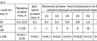
When choosing an inductive sensor to solve a specific problem, they are guided by the parameters of the circuit in which it will operate and the basic logic of the circuit. Therefore, the compliance of their parameters must be checked:
- supply voltage - determines the permissible minimum and maximum potential difference at which the inductive sensor operates normally;
- minimum operating current – the lowest load value at which switching will occur;
- actuation distance - the permissible distance distance at which switching will occur;
- inductive and magnetic resistance - determines the conductivity of electric current and magnetic induction lines for a specific model;
- correction factor - used to make corrections, depending on additional factors;
- switching frequency – the maximum possible number of switching times per second;
- overall dimensions and installation method.
Who makes limit switches
Many companies produce such sensors. Among them there are recognized leaders. Among them is the German company Sick, as the main manufacturer of such high quality products. Autonics supplies the market with contactless limit switches of inductive and capacitive types.
High quality contactless sensors are produced by the Russian company. They are characterized by ultra-high tightness (IP 68). These limit switches operate in the most hazardous environments, including explosive ones, and various installation methods are available.
Ukrainian limit switches are popular. Switches and limit switches VP, PP, VU are produced here. The warranty, subject to compliance with all operating rules, is 3 years.
Download instructions and manuals for some types of inductive sensors:
• Autonics_PR / Inductive proximity sensors.
Detailed description of the parameters, pdf, 135.28 kB, downloaded: 3164 times./ • Autonics_proximity_sensor / Catalog of Autonics proximity sensors, pdf, 1.73 MB, downloaded: 1867 times./
• Omron_E2A / Catalog of Omron proximity sensors, pdf, 1.14 MB, downloaded: 2441 times./
• TEKO_Table of interchangeability of switches from foreign manufacturers / How can TEKO sensors be replaced, pdf, 179.92 kB, downloaded: 1872 times./
• Turck_InduktivSens / Sensors from Turck, pdf, 4.13 MB, downloaded: 2395 times./
• pnp npn / Scheme for connecting sensors using PNP and NPN schemes in the Splan program/ Source file., rar, 2.18 kB, downloaded: 3781 times./