A 12V transformer power supply is used to convert the mains voltage to the level required for the operation of a specific device. Today, this type of power supply is equipped with protection systems against sudden voltage surges, short circuits, and to normalize high-frequency interference. The design is reliable with comparative simplicity and low cost. A power supply with a transformer type can be independently designed and assembled at home.
Types of power supplies
Today, switching voltage sources are widely used. Compared to traditional transformer circuits, they have a significant advantage in energy efficiency and weight and size indicators. It is believed that at load currents of more than 5 amperes they have undeniable preferences. But they also have disadvantages - for example, the generation of RF interference into the supply network and into the load. And the main obstacle to home assembly is the complexity of the circuits and the need for special skills to make winding parts. Therefore, it is better for a semi-skilled home craftsman to start making a power supply according to the usual principle with a network step-down transformer.
Homemade power supply circuit
Schemes on how to assemble a homemade transformer-type power supply were presented above, but for convenience we offer another diagram for your reference, with clear symbols.
This diagram shows a step-down transformer with two windings and a diode bridge for rectification.
This is a simple circuit that allows any novice electrician to assemble a homemade power supply with a transformer.
Transformer power supply circuit
Schematic diagram of the power supply.
The circuit of a 12 volt power supply operating from a 220 V network consists of the following components:
- A step-down transformer . It consists of iron, primary and secondary (there may be several) windings. Without going deeply into the principle of operation, it should be noted that the output voltage depends on the ratio of the turns of the primary (n1) and secondary (n2) windings. To obtain 12 volts, the secondary winding must contain 220/12 = 18.3 times fewer turns than the primary.
- Rectifier. Most often it is performed in the form of a full-wave circuit (diode bridge). Converts alternating voltage into pulsating voltage. The current passes through the load twice in one direction per period.
Operation of a full-wave rectifier. - Filter .
Converts pulsating voltage into constant voltage. It charges when voltage is applied and discharges during pauses. It consists of a high-capacity oxide capacitor, in parallel with which a ceramic capacitor with a capacity of about 1 μF is often connected. To understand the need for this additional element, we must remember that the oxide capacitor is designed in the form of strips of foil rolled into a roll. This roll has parasitic inductance, which significantly degrades the quality of filtering high-frequency interference. To do this, an additional HF pulse short-circuit capacitor is turned on. Equivalent filter circuit with oxide and additional capacitors. - Stabilizer . May be missing. Schemes of simple but effective units are discussed below.
The following sections discuss the procedure for selecting and calculating each element of a 12-volt DC voltage source.
Rectifier
The transformer power supply usually uses a bridge rectifier with one, two or four diodes.
We use a bridge rectification circuit
The use of a bridge rectifier is shown in this diagram:
How does it work
The operating principle of a bridge-type rectifier is as follows: during a half-cycle flow, the electric current flows through two diodes, which are switched on in the forward direction. This allows the capacitor to receive a ripple voltage at twice the frequency from the supply.
Above is a diagram of how to use a bridge-type rectifier in a design. To understand how a bridge-type DC and AC voltage rectifier works, you can use this diagram for reference:
The triangles in the diagram are diodes that allow the bridge rectifier to operate.
How to solder
To solder the bridge rectifier, use the following diagram:
Transformer selection
There are two ways to obtain a suitable transformer. Independent production of a step-down block and selection of a suitable one in the factory. In any case, you need to keep in mind:
- at the output of the step-down winding of the transformer, when measuring the voltage, the voltmeter will show the effective voltage (1.4 times less than the amplitude);
- on the filter capacitor without load, the constant voltage will be approximately equal to the amplitude voltage (they say that the voltage on the capacitor “rises” by 1.4 times);
- if there is no stabilizer, then under load the voltage on the capacitor will drop depending on the current;
- For the stabilizer to operate, a certain excess of the input voltage over the output voltage is required; their ratio limits the efficiency of the power supply as a whole.
From the last two points it follows that for normal operation of the power supply, the transformer voltage must exceed 12 V.
Principle of operation
The transformer on this type of power supply allows you to convert the 220V voltage received from a regular electrical network to the required voltage level for a specific device.
The generator of electromagnetic fields is a conductor through which alternating current passes, and due to the fact that it is wound into a coil on a transformer, its action is produced more tightly. According to the law of electromagnetic induction, an alternating field is induced in the secondary winding.
Self-winding transformer
The complete calculation and manufacture of a homemade power transformer is complex, time-consuming, and requires tools and skills. Therefore, a simplified path will be considered - selecting a block suitable for hardware and converting it to 12 V.
If there is a ready-made transformer, but there is no wiring diagram for it, you need to call its windings with a tester. The winding with the highest resistance will most likely be the mains winding. The remaining windings must be removed.
Next, you need to measure the thickness of the iron set b and the width of the central plate a and multiply them. The cross-sectional area of the core will be S=a*b (in sq.cm). It determines the power of the transformer P=
. Next, the maximum current in amperes is calculated, which can be removed from a winding with a voltage of 12 volts: I = P/12.
Determination of core area.
Next, the number of turns per volt is calculated using the formula n=50/S. For 12 volts, you need to wind 12*n turns with a margin of about 20% for losses in copper and on the stabilizer. And if it is not there, then the voltage drop under load. And the last step is to select the cross-section of the winding wire according to the schedule for a current density of 2-3 mA/sq.mm.
Selecting copper wire.
For example, there is a transformer with a 220 V primary winding with a set of iron 3.5 cm thick and a middle tongue width of 2.5 cm. This means S = 2.5 * 3.5 = 8.75 and the power of the transformer
=3 W (approx.) Then the maximum possible current at 12 volts is I=P/U=3/12=0.25 A. For winding, you can choose a wire with a diameter of 0.35..0.4 sq. mm. For 1 volt there are 50/8.75 = 5.7 turns, you need to wind 12 * 5.7 = 33 turns. Taking into account the reserve - about 40 turns.
Rewinding a transformer with your own hands. Case Study
Now, having understood some points that you need to know, let's start rewinding the transformer. Next, an example of rewinding in a “live story format” will be described, if I were to record all my actions in chronological order for you under a dictaphone :). So, the “Record” button is turned on, the cassette film with a characteristic rustling winds the film from one reel to another. It’s evening, the table lamp is burning on the table, and the smell of rosin is in the air...
A friend asked me to assemble a bipolar power supply to power the Yunost-21 synthesizer. It was necessary to obtain stable +/- 10 volts at the output. I did not find a specific transformer in my amateur radio stocks. It was decided to manufacture it ourselves to the required parameters. The basis for the modification was an armor-type transformer with an Ш-shaped magnetic core, which previously worked in the power supply of a single-channel amplifier. According to preliminary calculations, the total load on the transformer in the amplifier was 3A, which corresponded with a margin for the load of the designed power supply.
Taking into account the overall power of the transformer and the thickness of the wire of the secondary winding, I figured that the primary winding should be wound with wire of a suitable diameter (measurements with a micrometer after winding the secondary winding confirmed this). Measuring the no-load current also confirmed the suitability of the selected transformer (there was no need to rewind the primary)
All that remained was to deal with the secondary winding.
For a bipolar power supply, it is necessary to have two symmetrical windings designed for 1 Ampere load (the transformer for conversion already has them). We connect the transformer to a 220V network and measure the voltage at the taps of the windings. We write down the obtained values on a draft for subsequent calculations. Next, we disassemble the transformer to rewind it.
Unscrew the studs and remove the transformer brackets. Before us is a W-shaped armor-type magnetic circuit. It consists of W-shaped plates and I-shaped plates, which alternate with each other and are rearranged in a certain way.
To facilitate the disassembly process, carefully remove the varnish/paint
Removal of the paint coating (if necessary) is carried out extremely carefully so as not to damage the surface of the plates and not to leave a burr that can short circuit the magnetic circuit plates. If possible, we do without these manipulations.
First, the I-shaped plates must be removed. Carefully pry it up with a knife or a flat thin screwdriver, pry it up and pull them all out. After this, we remove the W-shaped plates from the transformer coil frame one by one.
After the transformer coil has been separated from the magnetic circuit, we proceed to further actions. We are now faced with the task of counting the number of turns in the secondary windings. We do not touch the primary winding.
Based on the measurement results, the two secondary windings have the same voltages and are symmetrical to each other (they mirror the number of turns). If we find out the number of turns of one winding, we will know how many there are in the other. After counting, you won’t have to completely wind up all the turns; we’ll just calculate how much wire needs to be wound in order to get the desired voltage.
Having sat down at the table in a calm atmosphere, we place in front of us a piece of paper, a pen (pencil) and a transformer coil. We begin to unwind the wire and count the turns being wound. After every ten winding turns, we mark a piece of paper with a mark, for example, a vertical line, which will correspond to 10 turns. We will do the same when winding wire onto a reel. This is necessary in order not to get confused and lose count. You can also use a simple calculator, adding the values of the turns.
Some tips:
-Before work, make sure that there are no sharp surfaces of furniture around you on which the winding wire may rub or get caught (do not damage the enamel insulation of the winding wires!);
-Wind the wire onto a separate reel. This way it will be laid evenly without damage, which will allow it to be reused;
-It is also important to carefully wind the wire to avoid the formation of loops and creases in the process - this way we will keep the wire relatively straight and will not damage the enamel coating of the copper wire when bending it
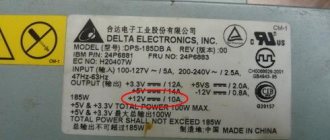
Selection of a finished transformer
If you have a ready-made transformer with a secondary winding suitable for current and voltage, you can try to select a ready-made one. For example, in the TPP series there are suitable products with a voltage of secondary windings close to 12 volts.
| Transformer | Designation of secondary winding terminals | Voltage, V | Allowable current, A |
| Chamber of Commerce and Industry48 | 11-12, 13-14, 15-16, 17-18 | 13,8 | 0,27 |
| TPP209 | 11-12, 13-15 | 11,5 | 0,0236 |
| TPP216 | 11-12, 13-14, 15-16, 17-18 | 11,5 | 0,072 |
The advantage of this solution is minimal labor intensity and reliability of factory execution. Minus - the transformer contains other windings, the overall power is also designed for their load. Therefore, in terms of weight and size, such a transformer will lose.
Metal power transmission line supports according to their intended purpose
According to the space they occupy in the power line, metal supports are divided into
- intermediate,
- corner,
- end,
- branch supports.
Often the supports that carry increased loads in the line are corner, end and branch supports; they are called anchor supports. You read anchored, understand reinforced.
The calculation of the load of manufactured supports is quite complex and, as a result, the marking of supports according to their purpose is also a little confusing. For example, multifaceted metal supports for 0.38 kV overhead power lines developed by ROSEP according to its specifications can be of the following types:
- Intermediate (P1M);
- Angular intermediate (UP1M);
- End anchor (K1M);
- Corner anchor (UA1M);
- Branch anchor (AO1M);
- Transitional intermediate (PP1M);
- Transitional anchor (PA1M);
- Transitional corner anchor (PUA1M);
- Transitional branch anchor (TAA);
- Transitional anchor branch (PAO).
Selecting diodes and making a rectifier
Diodes in the rectifier are selected according to three parameters:
- highest permissible forward voltage;
- highest reverse voltage;
- highest operating current.
According to the first two parameters, 90 percent of available semiconductor devices are suitable for operation in a 12-volt circuit; the choice is mainly made based on the maximum long-term permissible current. The design of the diode body and the method of manufacturing the rectifier also depend on this parameter.
If the load current does not exceed 1 A, you can use foreign and domestic one-ampere diodes:
- 1N4001-1N4007;
- HER101-HER108;
- KD258 (“droplet”);
- KD212 and others.
KD105 (KD106) devices are designed for lower currents (up to 0.3 A). All of the listed diodes can be mounted either vertically or horizontally on a printed circuit board or circuit board, or simply on pins. They don't need radiators.
Diode bridge made of low-power elements.
If large operating currents are needed, then other diodes must be used (KD213, KD202, KD203, etc.). These devices are designed for operation on heat sinks; without them they will withstand no more than 10% of the maximum rated current. Therefore, you need to select ready-made heat sinks or make them yourself from copper or aluminum.
Another diode bridge design.
It is also convenient to use ready-made bridge diode assemblies KTs405, KVRS or similar. There is no need to assemble them - just apply an alternating voltage to the corresponding terminals and remove the constant one.
Assembly of KVRS3510.
What is their difference and what is better to choose: let’s summarize
And so, generally speaking, the power supply, the electronic transformer, and the driver belong to the category of electrical converters. But, each of them has its own purpose in applied electronics. In theory, they are interchangeable, but most equipment they are designed for will not work with similar devices or will not work correctly.
What can each of them be used for:
- Driver – used to connect an LED; it is not practical to use a driver for other devices. The driver is already installed in the LED bulbs as a required component. However, it should be noted that a specific driver is used exclusively for a semiconductor or group of semiconductors that matches its parameters. If one of the LEDs burns out, the driver will no longer match the new current.
- Power supply - suitable for switching on low-voltage equipment with a constant supply voltage of 12 V, 24 V, etc. Often used to connect LED strips, since the strips already have variable resistors and do not need to limit the current. But they need to use a rectifier, which is provided by the power supply, since the LED is sensitive to any fluctuations in the supply quantities.
- Electronic transformer - often used for halogen lamps, which is due to the presence of a minimum load, without which it simply will not start. LED devices for an electronic transformer may not be enough, but halogen ones are more than enough. But the halogen lamps themselves can be turned on either from a transformer or from a power supply, since they operate from actual voltage.
Capacitor capacity
The capacitance of the capacitor depends on the load and the ripples it tolerates. To accurately calculate capacity, there are formulas and online calculators that can be found on the Internet. For practice, you can focus on the numbers:
- at low load currents (tens of milliamps), the capacitance should be 100..200 µF;
- at currents up to 500 mA, a capacitor of 470..560 μF is needed;
- up to 1 A – 1000..1500 µF.
For higher currents, the capacitance increases proportionally. The general approach is that the larger the capacitor, the better. Its capacity can be increased to any limit, limited only by size and cost. In terms of voltage, you need to take a capacitor with a serious margin. So, for a 12-volt rectifier it is better to take a 25-volt element than a 16-volt one.
These arguments are valid for unstabilized sources. For a power supply with a stabilizer, the capacity can be reduced significantly.
Filter
In transformer-type blocks, filtering and cutting off the component variables are mandatory. For this purpose, these devices use high-capacity electrolytic capacitors.
Purpose
An electrolytic capacitor, which acts as a filter in these devices, is used both when the unit operates with constant and alternating voltage. But in some cases, the choice of capacitor may be different.
Output voltage stabilization
A stabilizer at the output of the power supply is not always needed. So, if you plan to use a power supply in conjunction with sound-reproducing equipment, then the output must have a stable voltage. And if the load is a heating element, the stabilizer is clearly unnecessary. To power an LED strip, you can do without the most complex power supply module, but on the other hand, a stable voltage ensures independence of the brightness of the glow during changes in the network and extends the life of the LED lamp.
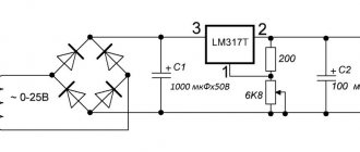
If the decision to install a stabilizer has been made, then the easiest way is to assemble it on a specialized microcircuit LM7812 (KR142EN5A). The connection circuit is simple and does not require adjustment.
Stabilizer for 7812.
The input of such a stabilizer can be supplied with voltage from 15 to 35 volts. A capacitor C1 with a capacity of at least 0.33 μF must be installed at the input, and at least 0.1 μF at the output. The capacitor of the filter unit usually acts as C1 if the length of the connecting wires does not exceed 7 cm. If this length cannot be maintained, then the installation of a separate element will be required.
The 7812 chip has protection against overheating and short circuit. But it does not like reversing the polarity at the input and applying external voltage to the output - its life time in such situations is calculated in seconds.
Important! For load currents above 100 mA, installing an integrated stabilizer on the heat sink is mandatory!
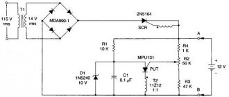
What is a triac
The thyristor has a drawback that complicates its use in an alternating current network - it passes through only one half-wave and the output produces a constant pulsating voltage instead of an alternating voltage. Therefore, these devices are used in pairs or together with a diode bridge. The triac is free from this drawback.
A triac is similar in appearance to a thyristor. Just like a thyristor, it opens with a current pulse flowing through the control electrode, but this device passes both half-waves through itself and is capable of operating in an alternating current network.
Schematic diagram of a triac current regulator for active and inductive loads. The design of a triac regulator is similar to a thyristor regulator. The difference is that the triac controls both polarities and therefore there is no need to use a diode bridge or back-to-back connection of elements.
In addition, the polarity of the control voltage does not matter for the triac, which simplifies the pulse control circuit.
Increasing the output current of the stabilizer
The above circuit allows you to load the stabilizer with a current of up to 1.5 A. If this is not enough, you can power the unit with an additional transistor.
Circuit with an NPN structure transistor
External NPN transistor.
This circuit is recommended by the developers and is included in the datasheet for the chip. The output current should not exceed the maximum collector current of the transistor, which must be equipped with a heat sink.
Circuit with pnp transistor
If there is no semiconductor triode of the npn structure, then you can power the stabilizer with a semiconductor triode pnp.
External PNP transistor.
A silicon low-power VD diode increases the 7812's output voltage by 0.6 V and compensates for the voltage drop across the transistor's emitter junction.
Parametric stabilizer
If for some reason an integrated stabilizer is not available, you can make a unit on a zener diode. It is necessary to select a zener diode with a stabilization voltage of 12 V and designed for the corresponding load current. The highest current for some 12-volt domestic and imported zener diodes is indicated in the table.
| Zener diode type | D814G | D815D | KS620A | 1N4742A | BZV55C12 | 1N5242B |
| Load current | 5 mA | 0.5 A | 50 mA | 25 mA | 5 mA | 40 mA |
| Stabilization voltage | 12 volts | |||||
Circuit diagram of a simple parametric stabilizer.
The resistor value is calculated using the formula:
R= (Uin min-Ust)/(In max+Ist min), where:
- Uin min – minimum input unstabilized voltage (must be at least 1.4 Ust), volts;
- Ust – zener diode stabilization voltage (reference value), volts;
- In max – highest load current;
- Ist min – minimum stabilization current (reference value).
If a zener diode for the required voltage is not available, it can be made up of two connected in series. In this case, the total voltage should be 12 V (for example, D815A at 5.6 volts plus D815B at 6.8 volts will give 12.4 V).
Important! You cannot connect zener diodes (even of the same type) in parallel “to increase the stabilization current!”
Zener diodes are not connected in parallel.
You can power up the parametric stabilizer in the same way - by turning on an external transistor.
Powerful stabilizer circuit.
For a powerful transistor, a radiator must be provided. The supply voltage in this case will be less than Ust of the zener diode by 0.6 V. If necessary, the output voltage can be adjusted upward by turning on a silicon diode (or chain of diodes). Each element in the chain will increase Uout by approximately 0.6 V.
Stabilizer circuit with zener diode and diode.
Output voltage regulation
If the power supply voltage needs to be regulated from zero, then the optimal circuit would be a parametric stabilizer with the addition of a variable resistor.
Smooth voltage regulation.
A 1 kOhm resistor connected between the base of the transistor and the common wire will protect the triode from failure if the potentiometer motor circuit breaks. When you rotate the variable resistor knob, the voltage at the base of the transistor will change from 0 to Ust of the zener diode with a lag of approximately 0.6 volts. It must be taken into account that the parameters of the node will be worse due to the use of a potentiometer - the presence of a moving contact (even of good quality) will inevitably reduce the voltage stability at the base of the transistor.
Low voltage in the network: why does this happen?
Reduced or weak load on the electrical network for a private home is not uncommon. Also, very often there is not enough power for the dacha. This fact causes a lot of inconvenience, not to mention the fact that a person cannot use the help of a washing machine. What to do in such a situation, where to call, complain, and most importantly, how to check the quality of the power supply yourself? Insufficient voltage in the network is an extremely unpleasant situation, but almost everyone faces it. If the lighting is poor and the light bulb only indicates its presence, then this is not a big problem. It will be worse when washing is not possible, boiling water is impossible, there is no way to cook food on an electric stove, or the refrigerator operates intermittently. This often happens when the network voltage is less than 180 volts. If everything works at this voltage, then this does not have a very good effect on the devices and the operation process takes a longer time.
Let us highlight several main reasons for low voltage:
- The cross-section of the cable that enters the house is incorrect;
- The switch is not connected correctly;
- The substation transformer is rebooting or has partially failed;
- The cross-section of the main line is small;
- Skewed phases.
These were the most common reasons listed. If you understand that the cause of low voltage in your home is the same as in points 1, 2 or 6, then you can correct the cause yourself. If the other 3 reasons or one of them suits you, then you should contact service stations.
Device layout
After all the components have been selected, or there is a clear idea of what they will be, you can begin to assemble the device. It is also important to understand what the future body of the device will be like. You can choose a ready-made one, or you can make it yourself if you have the materials and skills.
There are no special rules for the layout of components inside the housing. But it is advisable to arrange the nodes so that they are connected by conductors in series, as in the diagram, and over the shortest distance. It is better to place the output terminals on the side opposite the network cable. It is better to mount the power switch and fuse on the back wall of the device. To rationally use the inter-body space, some of the units can be installed vertically, but it is better to fix the diode bridge horizontally. When mounted vertically, convection currents of hot air from the lower diodes will flow around the upper elements and additionally heat them.
For those who don’t understand, watch the video: Simple DIY power supply.
Assembling a fixed supply DC power supply is not difficult. An average craftsman can do this; only basic knowledge of electrical engineering and minimal installation skills are needed.
Electronic autotransformer
A more modern way of adjustment is the use of electronic devices. Any of them can be made with your own hands.
Thyristor regulator
The simplest circuit of such a device is a variable resistor connected between the anode and the control electrode of the thyristor. This allows you to receive a pulsating DC voltage and control it in the range of 0-110V.
To regulate the alternating voltage 0-220V, an anti-parallel connection circuit is used, and a resistor is connected between the control electrodes.
Instead of two thyristors, it is advisable to use a triac, and use a dimmer for incandescent lamps as a control circuit.
Transistor control
The highest quality adjustment is obtained when using a transistor regulator. It provides a smooth change and correct shape of the output voltage.
The disadvantage of this circuit is that the output transistors heat up. To reduce it and increase efficiency, it is advisable to connect the regulator to the output terminals of the autotransformer - rough adjustment is carried out by switching windings, and smooth adjustment is carried out using transistors.
PWM controller
The most modern way is to use a PWM controller (pulse width modulation). Field-effect or insulated gate bipolar transistors (IGBTs) are used as power elements.