This abbreviation does not denote the switch itself, but its type, or rather, the type of switch contact circuit. From the above letters you can understand what kind of switching circuit is located in the housing.
The contact diagram of the switches cannot be laid out on the case, since there is not enough space; to simplify it, we came up with designations for the type of switch using a set of letters, thanks to which you can find out the number of poles and the number of directions (or circuits) in this switch. The number of poles is essentially inputs, i.e. number of electrically unrelated switches controlled by a common drive. The number of directions is the outputs, i.e. the contacts to which the poles are connected. The number of outputs (directions) and the number of inputs (poles) do not always match. In the USA, the terminology is different and is designated: Two-Way, Three-Way, Double Pole.
Application
Solid state relays are used to control electronic devices, equipment and automatic systems connected to an electrical network with a power of 20 to 480 watts.
Used in various fields:
- automation of industrial processes;
- various household installations;
- heat regulation systems in heating elements;
- in lighting control systems and motion sensors;
- car electronics.
The relay is found in refrigerators, kettles, washing machines, heating elements, and uninterruptible power supplies.
The areas of use of solid-state devices depend on their design, connection diagrams and other operating conditions.
TSRs do not require constant maintenance and can be installed in any hard-to-reach places.
The popularity of solid-state devices is increasing every day, thanks to widespread automation.
DPDT
This abbreviation “ DPDT ” stands for Double Pole - Double Throw. They are essentially two SPDT switches that have two poles and two directions. They have two poles (contacts), each of which can be connected to one contact or to the other. Each group is not electrically connected to each other. Each of them can switch completely different circuits. They have only one thing in common: they work simultaneously. Example, relay RES-9. But there are switches with a large number of contacts, for example four groups, this is the RES-22 relay.
Types and classification
By installation method
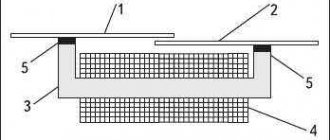
Various models of SSRs are available with mounting on supporting surfaces, printed circuit boards or DIN rails.
Figure 3. Device for installation on a printed circuit board.
To cool the relay, special radiators are used, installed between the support and the block.
For additional protection against overheating, thermal paste is applied to the surface of the device to increase heat transfer by increasing the contact area.
There are models designed to be attached directly to the wall with screws.
For installation in an electrical panel, TTRs with DIN rail mounts are available.
Rail mounting.
To remove excess heat, the relay is attached to the rail through brackets.
By type of switching network switching
The devices differ:
- With a “through zero” regulator. Triggered at zero voltage. Designed for devices with weak inductive, resistive or capacitive loads.
- Instant. Used when sudden operation is required.
- Phase. In such devices, when the resistance value changes, the power at the load changes. It is used to adjust the lighting level in incandescent lamps, or the temperature in heating elements.
By type of operating current
Solid state relays can be controlled by electrical circuits with two types of current:
- permanent;
- variables.
DC switching is used at constant voltages up to 32 volts.
Most operate on alternating currents. Such devices are characterized by instantaneous operation, efficiency and low degree of electromagnetic interference. Operating voltages are 90-250 volts.
By number of connected phases
There are:
- Single-phase, operating in the range of 10-100 and 100-500A, are installed in household appliances.
- Three-phase, 10-120 A, switching voltage on three phases at once.
Single-phase devices are controlled using an analog signal and a variable resistor.
The design of three-phase relays involves reversible operation, providing regulation of several electrical circuits simultaneously.
Three phase relay
To make the correct connection when installing equipment, wires of different colors are connected to the three-phase relay.
One-letter symbolism of elements
Letter codes corresponding to individual types of elements most widely used in electrical circuits are combined into groups designated by one symbol. Letter designations correspond to GOST 2.710-81. For example, the letter “A” refers to the “Device” group, consisting of lasers, amplifiers, remote control devices and others.
The group denoted by the symbol “B” is deciphered in the same way. It consists of devices that convert non-electrical quantities into electrical ones, which does not include generators and power supplies. This group is complemented by analogue or multi-digit converters, as well as sensors for indications or measurements. The components themselves included in the group are represented by microphones, loudspeakers, sound pickups, ionizing radiation detectors, thermoelectric sensitive elements, etc.
All letter designations corresponding to the most common elements are combined into a special table for ease of use:
| The first letter character required to be reflected in the marking | Group of main types of elements and devices | Elements that make up the group (the most typical examples) |
| A | Devices | Lasers, masers, remote control devices, amplifiers. |
| B | Equipment for converting non-electrical quantities into electrical ones (without generators and power supplies), analogue and multi-charge converters, sensors for indications or measurements | Microphones, loudspeakers, sound pickups, ionizing radiation detectors, sensitive thermoelectric elements. |
| C | Capacitors | Capacitors with different capacities |
| D | Microassemblies, integrated circuits | Digital and analog integrated circuits, memory and delay devices, logic elements. |
| E | Miscellaneous elements | Various types of lighting devices and heating elements. |
| F | Designation of the fuse on the diagram, arresters, protective devices | Fuses, arresters, discrete current and voltage protection elements. |
| G | Power supplies, generators, crystal oscillators | Rechargeable batteries, power supplies on an electrochemical and electrothermal basis. |
| H | Signal and indication devices | Indicators, light and sound signaling devices |
| K | Contactors, relays, starters | Voltage and current relays, time relays, electrothermal relays, magnetic starters, contactors. |
| L | Chokes, inductors | Chokes in fluorescent lighting. |
| M | Engines | DC and AC motors. |
| P | Measuring instruments and equipment | Counters, clocks, indicating, recording and measuring instruments. |
| Q | Switches and disconnectors in power circuits | Power circuit breakers, short circuiters, disconnectors. |
| R | Resistors | Varistors, variable resistors, thermistors, potentiometers. |
| S | Switching devices in signaling, control and measuring circuits | Various types of switches and switches, as well as switches triggered by various factors. |
| T | Transformers, autotransformers | Stabilizers, voltage and current transformers. |
| U | Various types of converters and communication devices | Rectifiers, modulators, demodulators, discriminators, frequency converters, inverters. |
| V | Semiconductor and vacuum devices | Diodes, thyristors, transistors, zener diodes, vacuum tubes. |
| W | Antennas, lines and elements operating at ultrahigh frequencies. | Antennas, waveguides, dipoles. |
| X | Contact connections | Sockets, current collectors, pins, dismountable connections. |
| Y | Mechanical devices with electromagnetic drive | Cartridge brakes, electromagnetic clutches. |
| Z | End devices, limiters, filters | Quartz filters, modeling lines. |
Design
The main element of solid-state relays is an electronic board consisting of three main elements:
- A control unit that provides stable voltage levels, which at the input ranges from 70 to 220 Volts.
- Interchange unit , consisting of elements that send and receive a light signal. A transparent dielectric is located between the transmitting and receiving elements.
- Power keys:
- for direct current - based on transistors.
- for variable - on base
triacs or thyristors.
Relay internals.
The device must be mounted after the load, followed by grounding, to prevent short circuits.
Connection diagrams
Electrical circuits are constructed depending on the characteristics of the load connection.
The most common schemes include:
- Open or open . When a control signal is present, the relay is energized. When the inputs are de-energized, the devices are in a switched off state.
- Closed. In the absence of a control signal, the relay load is energized. When the inputs are de-energized, the connected devices are in working order.
- Three-phase - contacts are connected according to the “Star”, “Star-neutral” or “Triangle” circuit.
- Reversible - include two levels of control. Manufactured in a three-phase version.
Electrical circuits with solid-state relays are assembled exactly according to the diagram, observing polarity.
Incorrect connection of devices can lead to electric shock or failure due to short circuit.
Sandbox: Endgames
Good afternoon, dear readers!
This topic will be relevant for beginners. Experienced 3D makers will most likely not be interested. Today I will try to talk about limit switches. In order for the 3D printer carriage to understand its extreme position, the origin point with coordinates X0, Y0, Z0, it is necessary to use EndStop or, as we call them, limit switches (limit switches). There are different types of end caps:
- Mechanical;
- Optical;
- Magnetic;
- Other.
Mechanical ones, in turn, are divided into regular and indicator ones. A mechanical limit switch is essentially a simple switch (button) that is activated when it comes into contact with the carriage. When the limit switch is triggered, a signal is sent to the microcontroller port. Based on this signal, the microcontroller turns off the stepper motor (SM) and rolls the carriage back a few mm. Regular limit switch
Regular limit switch, has contacts COM, NO, NC.
In the open position:
The COM and NC contacts are at +5V. NO contact - ground (GND) COM and NC contacts are closed.
In closed position:
Our contacts COM (+5V) and NO (GND) are closed. The COM and NC contacts open. To connect, you need two wires, red and black. When triggered, a click is heard.
Indicator limit switch
The indicator one has the same contacts except for the presence of a third wire (green). Red wire - 'V' VCC +5V Black wire - 'G' GND - Ground Green wire - 'S' Signal +5V
The principle of operation is the same as that of a simple limit switch, but it has an LED that lights up when triggered. Three wires are required for connection. When triggered, a click is heard and the LED lights up. Optical limit switch
An optical pair is installed inside the optical end switch, which is triggered when an “obstacle” appears that falls into the gap between the LED and the photoresistor. Such limit switches are considered more accurate compared to mechanical limit switches. They cost more, but it is better to install them if possible. The operation is silent; when activated, the LED lights up. May not work in sunlight or dust, false alarms may occur.
SourceOn the board there are letters near the connector - V, S, G. Red wire - 'V' VCC +5V Black wire - 'G' GND - Ground Green wire 'S' Signal Operating principle of optical limit switches
5v is supplied to the LED through a limiting (pull-up) resistor.
The resistance of the photodiode/phototransistor is measured. For 5V logic, resistance installed on the sensor R1=180 Ohm (181); R2=2.2 kOm (222); R3=1 kOm (102). Source High signal ~5v (closed), low ~3v (open) Magnetic limit switch
Hall sensor - the sensor is triggered when a magnetic field (polarity) appears from the source.
Nowadays there are analogue and digital sensors. Digital, in turn, can be divided into unipolar
and
bipolar
.
Unipolar
- they operate in the presence of a field of a certain polarity and turn off when the field induction decreases.
Bipolar
- react to a change in field polarity, that is, one polarity turns on the sensor, the other turns it off. Also has 3 pins and is based on TLE4905L.
Source I would also like to note such delights as a proximity sensor, a pressure sensor, a sensor based on a piezo emitter, but that’s a completely different story...
firmware
supports mechanical and optical sensors.
For mechanical ones, the following values must be specified in the configuration.h file: For mechanical limit switches: const bool X_MIN_ENDSTOP_INVERTING = false; const bool Y_MIN_ENDSTOP_INVERTING = false; const bool Z_MIN_ENDSTOP_INVERTING = false; For optical end switches: const bool X_MIN_ENDSTOP_INVERTING = true; const bool Y_MIN_ENDSTOP_INVERTING = true; const bool Z_MIN_ENDSTOP_INVERTING = true; After this, the operation of the limit switches can be checked using the M119 command in the console. The response should be the following text: x_min: open - the limit switch did not work, x_min: TRIGGERED - the limit switch worked, Installation
Usually, only minimal (left) limit switches are installed on a 3D printer, they are installed only for the sake of the Home command [
G28 Y0 X0 Z0]
Maximum limit switches (right ) are not installed, since the firmware has a software limitation and the printer (if there are no problems) will not go beyond the limits set in the firmware.
You can also define maximum limit switches for the Home position. To do this, you need to change the value from -1 MIN to 1 MAX (1 = MAX, -1 = MIN) #define X_HOME_DIR 1 #define Y_HOME_DIR 1 #define Z_HOME_DIR 1 Connection
We connect the minimum limit switches to the RAMPS to the contacts X- Y- Z-, + 5V (red), GND (black), S (green/yellow).
In my printer, I implemented the connection of limit switches along the X and Y axes mechanically, and optically along the Z axis. I think this is relevant for the Z axis, but not important for other axes. The limit switch along the X axis had to be slightly altered, since the limit switch I had was not convenient to attach to my carriage and it had a short arm. The result is a collective farm like this, the end switch works thanks to that.
The optical end switch was sold with a white wire; its contact order is different. The wire was replaced with a regular three-color one (taken from an old mechanical limit switch), and the wires in the chip were also swapped. The result is the following diagram: - End switch Red-Green-Black - RAMPS Red-Black-Green
Now you can connect as usual.
Thank you all for your attention!
Operating principle
To understand the operating principle of solid-state relays, you need to know their design features.
The interaction of the controlled and control signal is ensured by galvanic or optical isolation.
One of the main elements of the SSR is an opto-isolator, or optocoupler in the form of an LED and a photosensitive device that isolates the input from the output.
When electricity passes through the LED connected to the input section of the solid state relay, it lights up. Focusing through the gap, the light is transmitted to a photosensitive transistor or semistor.
The principle of operation of the device is to close and open contacts that transmit voltage.
The circuitry of all solid-state devices is approximately the same. Minor differences between different models do not affect its functionality at all.
The mechanism works by closing and opening the contact terminals that transmit voltage.
Specifications
When choosing a TSR, one is guided by the following characteristics:
- dimensions;
- voltage value at the input and output;
- overload capacity;
- power consumption;
- material of manufacture;
- type of installation;
- insulation strength, etc.
The characteristics of solid-state relays may vary depending on the type of device.
Table 1. Average characteristics of TSR.
| Name | Index |
| Operating currents | no more than 7.5 mA |
| Insulation resistance | >50 MOhm/500V DC |
| Relay control method for DC current | instantly via optocoupler |
| Switching method in relays for alternating current | when crossing zero |
| Overload capacity | up to 10 rated currents for 10 ms |
| Built-in protection | replaceable fuses |
| Insulation strength | 2.5 kV AC for 1 minute |
Diagram of symbols used in the relay.
Diagram of symbols used in the relay.
Relay contact designation.
COM is the common contact of the relay, which is movable.
Often denoted as BASE or COMMON. The common contact is also called a pole, and those with which it connects are called directions. NC (Normal Close) – contact with which the common is normally closed (normally closed). This means that the contacts are closed when the relay is de-energized and open when current is applied to the control coil.
NO (Normal open) – contact with which the common is normally open (normally open). Those. when the relay is de-energized, the contacts are open, and when voltage is applied to the coil, the contacts are closed.
In the circuit with NC we see that current flows through the relay when the coil is de-energized and in order to open the circuit we need to apply voltage to the coil, and in the second case, with the coil de-energized and no current flows through the relay contacts.
The normal state is the original state of the relay. But it is worth noting that there are types of relays, for example, polarized ones, for which there is no concept of a normal state, since it can change, and accordingly the NO contact can become NC and vice versa.
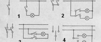
Types of switches.
According to the type of switching, all relays can be divided into 2 main types:
— the relay opens or closes the contact (SPST). Such a relay has one input and one output, and works like a key. Moreover, one such relay can contain several pairs of independent contacts, i.e. have several databases with your own contacts (DPST).
— the relay switches between two or more contacts (SPDT. There is one base, but there may be several outputs. Such relays can also have several pairs of contacts (DPDT).
SPDT (Single Pole, Double Throw). One pole, two directions. Those. There is one common contact that can be switched in two directions.
DPDT (Double Pole, Double Throw). Two poles in two directions, i.e. 2 groups of switches. Essentially these are two SPDT relays in one, but sharing a common coil. Sometimes a DPDT type relay is designated -2SPDT. In this way, relays with a much larger number of switches can be implemented.
SPST (Single Pole, Single Throw). One pole per direction. Formally, this is a controlled switch that can be either normally closed or normally open.
DPST (Double Pole, Single Throw). Two poles in one direction. A double pole DPST relay is equivalent to two SPST switches (NO Normally Open and NC Normally Closed) and can be used to switch two different loads.
We have 2 scenarios depending on the relay type
Without coil voltage:
With NO, the loads will be OFF as no current can flow.
With NC the loads will be ON as current can flow
With coil voltage:
With NO, the loads will be ON as current can flow.
With NC the loads will be OFF as no current can flow.
Designation options.
On complex relay combinations you can find detailed designations for the types of switches. As already written above, a DPDT relay can be designated as 2SPDT, although everything is clear here, but in the case of DPST NC-NO we can choose not which of the directions is normally closed, but which is normally open, so a designation like 2SPST-1NC- is introduced. 1NO.
We must understand that in this situation DPST NC-NO = 2SPST-1NC-1NO.
General table of symbols.
| Switching type | Switching type (alternative designation) | Switching diagram | Description |
| SPST-NO | A | SPST-NO (Single Pole Single Throw – Normally Open) One contact per switch, normally open | |
| SPST-NC | B | SPST–NO (Single Pole Single Throw — Normally Closed) One contact to turn on, normally closed | |
| SPDT | C | SPDT (Single Pole Double Throw) One contact per switch | |
| DPST-NO (2SPST-2NO) | 2A | DPST NO (Double Pole Single Throw, Normally Open) Two switching contacts, normally open | |
| DPST-NC (2SPST-2NC) | 2B | DPST NC (Double Pole Single Throw, Normally Closed) Two switching contacts, normally closed | |
| DPST NC-NO (2SPST-1NC-1NO) | 1A1B | DPST-NC-NO (Double Pole Single Throw- Normally Closed - Normally Open) Two switching contacts: one normally closed, the other normally open | |
| DPDT | 2C | DPDT (Double Pole Double Throw) Two switching contacts |
The difference between solid state relays and electromagnetic ones
Electromagnetic models have a control coil and a movable contact group.
The coil is supplied with voltage from a push-button station or control system.
Electricity flowing through the coil creates an electromagnetic field that attracts the armature with the contact group. The contacts are closed.
The main difference between solid-state relays is the absence of a control coil and a movable power contact group.
Depending on the scope of application, the functions of power contacts are performed by transistors, thyristors, triacs and other semiconductor switches.
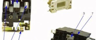
Due to the absence of moving parts, solid-state relays are not subject to mechanical wear.
Figure 7. Disassembled device.
Helpful information
Other related articles:
- Operating principle of the vacuum relay, general information. -High voltage vacuum relays. Areas of use. -High voltage vacuum relays. Basic terms and definitions.
Relay contact designation.
COM is the common contact of the relay, which is movable. Often denoted as BASE or COMMON. The common contact is also called a pole, and those with which it connects are called directions.
NC (Normal Close) – contact with which the common is normally closed (normally closed). This means that the contacts are closed when the relay is de-energized and open when current is applied to the control coil.
NO (Normal open) – contact with which the common is normally open (normally open). Those. when the relay is de-energized, the contacts are open, and when voltage is applied to the coil, the contacts are closed.
In the circuit with NC we see that current flows through the relay when the coil is de-energized and in order to open the circuit we need to apply voltage to the coil, and in the second case, with the coil de-energized and no current flows through the relay contacts.
The normal state is the initial state of the relay (with the coil de-energized). But it is worth noting that there are types of relays, for example, polarized ones, for which there is no concept of a normal state, since it can change, and accordingly the NO contact can become NC and vice versa.
Types of switches.
According to the type of switching, all relays can be divided into 2 main types:
— the relay opens or closes the contact (SPST). Such a relay has one input and one output, and works like a key. Moreover, one such relay can contain several pairs of independent contacts, i.e. have several databases with your own contacts (DPST).
- the relay switches between two or more contacts (SPDT). There is one base here, but there may be several exits. Such relays can also have several pairs of contacts (DPDT).
SPDT (Single Pole, Double Throw). One pole, two directions. Those. There is one common contact that can be switched in two directions.
DPDT (Double Pole, Double Throw). Two poles in two directions, i.e. 2 groups of switches. Essentially these are two SPDT relays in one, but sharing a common coil. Sometimes a DPDT type relay is designated -2SPDT. In this way, relays with a much larger number of switches can be implemented.
SPST (Single Pole, Single Throw). One pole per direction. Formally, it is a controlled switch that can be either normally closed (NC) or normally open (NO).
DPST (Double Pole, Single Throw). Two poles in one direction. A double pole DPST relay is equivalent to two SPST switches (NO Normally Open and NC Normally Closed) and can be used to switch two different loads.
We have 2 scenarios depending on the relay type
Without coil voltage:
With NO, the loads will be OFF as no current can flow.
With NC the loads will be ON as current can flow
With coil voltage:
With NO, the loads will be ON as current can flow.
With NC the loads will be OFF as no current can flow.
Designation options.
On complex relay combinations you can find detailed designations for the types of switches. As already written above, a DPDT relay can be designated as 2SPDT, although everything is clear here, but in the case of DPST NC-NO we can choose not which of the directions is normally closed, but which is normally open, so a designation like 2SPST-1NC- is introduced. 1NO.
We must understand that in this situation DPST NC-NO = 2SPST-1NC-1NO.
General table of symbols.
| Switching type | Switching type (alternative designation) | Switching diagram | Description |
| SPST-NO | A | SPST-NO (Single Pole Single Throw – Normally Open) One contact per switch, normally open | |
| SPST-NC | B | SPST–NC (Single Pole Single Throw - Normally Closed) One contact to turn on, normally closed | |
| SPDT | C | SPDT (Single Pole Double Throw) One contact per switch | |
| DPST-NO (2SPST-2NO) | 2A | DPST NO (Double Pole Single Throw, Normally Open) Two switching contacts, normally open | |
| DPST-NC (2SPST-2NC) | 2B | DPST NC (Double Pole Single Throw, Normally Closed) Two switching contacts, normally closed | |
| DPST NC-NO (2SPST-1NC-1NO) | 1A1B | DPST-NC-NO (Double Pole Single Throw- Normally Closed - Normally Open) Two switching contacts: one normally closed, the other normally open | |
| DPDT | 2C | DPDT (Double Pole Double Throw) Two switching contacts |
Advantages and disadvantages
The advantages of solid-state models include:
- absence of noise and vibration;
- compact dimensions;
- wide scope of application;
- instantaneous switching speed (thousandths of milliseconds);
- no electromagnetic interference when turned on;
- long service life due to the absence of moving parts;
- constant output resistance throughout the entire service life;
- minimal electrical energy consumption;
- possibility of load regulation;
- low sensitivity to vibrations, high humidity, dust, and magnetic fields.
The switching life of solid-state relays is a thousand or more times higher than that of electromagnetic analogues.
When operating such devices, the possibility of sparks occurring during switching is eliminated, which allows the devices to be used in explosion- and fire-hazardous facilities.
The main disadvantages of solid-state relays:
- heating of the device due to high resistance in the pn junction circuit;
- frequent false alarms during power surges;
- the possibility of failure of the power switch due to overloads and short circuits;
- high price.
The SSR has a leakage current, due to which the phase wire may be energized even when the relay is turned off.
Devices designed to operate in direct current conditions require strict adherence to polarity when connecting output circuits.
Solid state relays are periodically checked for package integrity and insulation.
What does normally closed NC and normally open contact NO mean?
/ 13 Details Details Category: Electrical Created 23.11.2016 23:12 Published 23.11.2016 23:47 Silin Stanislav Olegovich
Have a good day, dear and much-respected readers of my site. In this article I want to tell you what NO and NC are. And in simple terms, normally closed and normally open contacts.
1. What are NO and NC needed for? 2. Explanation on the fingers. 3. Examples of using NO, NC. 4. Schemes of use. 5. Video review.
1. What are NO and NC needed for?
If we decipher the abbreviation, we get NO - Normal Open, NC - Normal Closed. In fact, if you see such inscriptions NO and NC on equipment, then you should immediately be overcome with joy. Because with the help of these contacts you can easily carry out various types of control depending on the conditions.
2. Explanation on the fingers.
In fact, everything is very simple if you see something like this: If you measure their state, whether the circuit is closed or open, with the network turned off, you will get: In fact, this is the meaning of NO and NC, this is the state of the indicated contacts without power supply . Then you can change their state programmatically (Program task: “transfer NO to NC at 18.00 and return it to its previous state at 18.07”, and on this NC - you have the supply phase for irrigation “hanging”, for example), or it will change itself during a certain event (the sensor “sensed” a gas leak and switched contact from NO to NC, which triggered the alarm.
3. Examples of using NO, NC.
Examples of using these contacts are simply limitless, for example
* In a wide variety of sensors (water leaks, gas leaks, smoke sensor, etc.) * Smart home relay modules. * Control panels for alarm systems. * DVRs. * Starters (when it is necessary to increase the controlled power). * In water valves (indicates the status of the valve without electricity supply).
4. Schemes of use.
In a smart home, these contacts are used constantly; in fact, the entire smart home is built on them; the relay outputs are controlled by software:
If the contact does not have enough power, for example, your contacts are designed for a load of 1 kW, otherwise they will burn out or stick (weld), and you need to turn on a load of 1.5 kW, then the circuit can be assembled using a starter:
5. Video review:
Selecting a Solid State Relay
The overload properties of SSRs that switch alternating current are significantly higher than those of devices that switch direct current.
Table 2. Relay overload capacity.
| Current type | Permissible maximum overload (Ampere) during 10 ms. | ||
| Constant | 90 | 250 | 380 |
| Variable | 120 | 300 | 410 |
When choosing, you need to consider the following aspects:
Switching methods
The most popular devices are those in which control is performed when passing through “0”.
This type of switching is suitable for resistive type loads. The method allows you to eliminate interference created when turned on.
Phase control
The phase method is used in resistive lighting control circuits, transformers, and infrared emitters.
The regulation process in phase control is smooth and seamless. The disadvantage of this method is the appearance of interference during switching.
Phase controlled relay.
A relay with a phase regulator can be recognized by its symbol on the body, in the area where the input terminals are located.
Parameters and types of loads
Load current is one of the most important parameters when choosing a relay.
For reliable operation, choose a relay with a reserve:
- 30-40% - with active load (heaters);
- 6-10% - for asynchronous electric motors;
- 8-12% - for incandescent lamps;
- 4-10% - for electromagnetic relay coils.
Particular attention is paid to the following parameters:
| 1. Load current limit | ranging from 10 to 500 amperes |
| 2. Switchable voltage level |
|
| 3. Control signal |
|
To connect an inductive load (for example, an electric motor), it is necessary to take into account the starting current, which exceeds the rated current by 600-100%
Availability of cooling
The reliability of solid-state relays depends on its operating temperature.
The temperature should not be allowed to exceed 60°C.
The temperature regime of the relay is influenced by various factors:
- ambient temperature;
- installation location;
- existing loads;
- presence of air circulation.
When using relays at high currents, excess heat should be removed to cooling radiators, fans or other cooling options should be provided.
When heated, for every 10°C the throughput of the device decreases by 20-25%. When solid-state relays heat up to 80°, the product fails.
Protection
There are various options for protecting solid state relays:
- RC circuit - against false triggering when operating on an inductive load.
- Varistors - for protection against short-term voltage surges on the load side. Devices are selected taking into account the value of the switching voltage (from 1.6 to 2).
- Semiconductor fuses - provide overload protection. It should be taken into account that the device current is up to 30% of the rated current.
- Shunt resistors mounted in parallel to the load ensure correct operation at low currents.
Relay design, designation and parameters
An electromagnetic relay is actively used to control various actuators, switch circuits, and control devices in electronics.
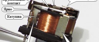
The relay design is quite simple. Its basis is a coil consisting of a large number of turns of insulated wire.
A soft iron rod is installed inside the coil. The result is an electromagnet. There is also an anchor in the relay design. It is attached to a spring contact. The spring contact itself is fixed to the yoke. Together with the rod and the armature, the yoke forms a magnetic circuit.
If the coil is connected to a current source, the resulting magnetic field magnetizes the core. He, in turn, attracts the anchor. The anchor is mounted on a spring contact. Next, the spring contact closes with another fixed contact. Depending on the relay design, the armature may mechanically control the contacts differently.
Relay device.
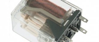
In most cases, the relay is mounted in a protective housing. It can be either metal or plastic. Let's look at the relay device more clearly, using the example of an imported Bestar electromagnetic relay. Let's take a look at what's inside this relay.
Here is the relay without the protective housing. As you can see, the relay has a coil, a rod, a spring contact on which the armature is attached, as well as actuating contacts.
On circuit diagrams, an electromagnetic relay is designated as follows.
The relay symbol in the diagram consists of two parts. One part (K1) is the symbol of the electromagnetic coil. It is designated as a rectangle with two terminals. The second part (K1.1; K1.2) are groups of contacts controlled by the relay. Depending on its complexity, a relay can have a fairly large number of switched contacts. They are divided into groups. As you can see, the designation shows two groups of contacts (K1.1 and K1.2).
How does a relay work?
The principle of operation of the relay is clearly illustrated by the following diagram. There is a control circuit. This is the electromagnetic relay K1 itself, the switch SA1 and the power battery G1. There is also an actuator circuit that is controlled by a relay. The executive circuit consists of load HL1 (signal lamp), relay contacts K1.1 and battery G2. The load can be, for example, an electric lamp or an electric motor. In this case, the HL1 signal lamp is used as a load.
As soon as we close the control circuit with switch SA1, current from power battery G1 will flow to relay K1. The relay will operate and its contacts K1.1 will close the actuator circuit. The load will receive power from battery G2 and lamp HL1 will light up. If you open the circuit with switch SA1, then the supply voltage will be removed from relay K1 and the contacts of relay K1.1 will open again and the lamp HL1 will turn off.
Switched relay contacts can have their own design. For example, a distinction is made between normally open contacts, normally closed contacts and switching contacts. Let's look at this in more detail.
Normally open contacts
Normally open contacts are relay contacts that remain open until current flows through the relay coil. To put it simply, when the relay is turned off, the contacts are also open. In diagrams, relays with normally open contacts are designated like this.
Normally closed contacts
Normally closed contacts are relay contacts that remain closed until current flows through the relay coil. Thus, it turns out that when the relay is turned off, the contacts are closed. Such contacts are shown in the diagrams as follows.
Switching contacts
Switching contacts are a combination of normally closed and normally open contacts. Switching contacts have a common wire that switches from one contact to another.
Modern widespread relays, as a rule, have switching contacts, but there may also be relays that have only normally open contacts.
For imported relays, normally open relay contacts are abbreviated NO. And normally closed contacts are NC. The common relay contact is abbreviated COM. (from the word common - “general”).
Now let's turn to the parameters of electromagnetic relays.
Parameters of electromagnetic relays.
As a rule, the dimensions of the relays themselves allow their main parameters to be printed on the housing. As an example, consider the imported Bestar BS-115C relay. The following inscriptions are written on its body.
COIL 12VDC is the rated operating voltage of the relay (12V). Since this is a direct current relay, the abbreviation for constant voltage is indicated (the abbreviation DC stands for direct current/voltage). The English word COIL is translated as “coil”, “solenoid”. It indicates that the abbreviation 12VDC refers to the relay coil.
Further on the relay the electrical parameters of its contacts are indicated. It is clear that the power of the relay contacts may be different. This depends both on the overall dimensions of the contacts and on the materials used. When connecting a load to the relay contacts, you need to know the power for which they are designed. If the load consumes more power than the relay contacts are designed for, then they will heat up, spark, and “stick.” Naturally, this will lead to rapid failure of the relay contacts.
For relays, as a rule, the parameters of alternating and direct current that the contacts can withstand are indicated.
For example, the contacts of the Bestar BS-115C relay are capable of switching an alternating current of 12A and a voltage of 120V. These parameters are encrypted in the inscription 12A 120VAC (the abbreviation AC stands for alternating current).
The relay is also capable of switching direct current with a power of 10A and a voltage of 28V. This is evidenced by the inscription 10A 28VDC. These were the power characteristics of the relay, or rather its contacts.
Relay power consumption.
Now let's turn to the power that the relay consumes. As you know, direct current power is equal to the product of voltage (U) and current (I): P=U*I. Let's take the values of the rated operating voltage (12V) and current consumption (30 mA) of the Bestar BS-115C relay and get its power consumption.
Thus, the power of the Bestar BS-115C relay is 360 milliwatts (mW).
There is another parameter - the sensitivity of the relay. At its core, this is the power consumption of the relay in the on state. It is clear that a relay that requires less power to operate is more sensitive compared to those that consume more power. A parameter such as relay sensitivity is especially important for self-powered devices, since the switched on relay consumes battery power. For example, there are two relays with power consumption of 200 mW and 360 mW. Thus, a 200 mW relay is more sensitive than a 360 mW relay.
How to check the relay?
The electromagnetic relay can be checked with a conventional multimeter in ohmmeter mode. Since the relay coil winding has active resistance, it can be easily measured. The resistance of the relay winding can vary from several tens of ohms (Ω) to several kilo-ohms (kΩ). Typically, the lowest winding resistance is found in miniature relays that are rated at 3 volts. Relays rated at 48 volts have much higher winding resistance. This can be clearly seen from the table, which shows the parameters of the Bestar BS-115C series relay.
| Rated voltage (V, constant) | Winding resistance (Ω ±10%) | Rated current (mA) | Power consumption (mW) |
| 3 | 25 | 120 | 360 |
| 5 | 70 | 72 | |
| 6 | 100 | 60 | |
| 9 | 225 | 40 | |
| 12 | 400 | 30 | |
| 24 | 1600 | 15 | |
| 48 | 6400 | 7,5 |
Note that the power consumption of all types of relays in this series is the same and amounts to 360 mW.
An electromagnetic relay is an electromechanical device. This is probably the biggest plus and at the same time a significant minus.
With intensive use, any mechanical parts wear out and become unusable. In addition, the contacts of powerful relays must withstand enormous currents. Therefore, they are coated with precious metal alloys such as platinum (Pt), silver (Ag) and gold (Au). Because of this, high-quality relays are quite expensive. If your relay still fails, then you can replace it.
The positive qualities of electromagnetic relays include resistance to false alarms and electrostatic discharges.
Home » Radio electronics for beginners » Current page
You might also be interested to know:
- Triac.
- Parameters of MOS transistors.
Short circuit protection
Short circuits can occur when the insulation in the electrical circuit is damaged, external influences or network overload.
To protect against short circuits, fast-acting fuses designed specifically for solid-state relays are used. Such devices are capable of breaking the circuit much faster than breakdown of the input element.
The most important indicator of fuses is the speed of operation.
The rated current values of fuse links are indicated by the manufacturer in the technical documentation. They must be higher than the maximum currents of the protected devices.
After tripping, the fuses must be replaced.
SSR connection
When connecting the relay, polarity must be strictly observed.
Voltage is supplied to the control inputs. Loads are connected to the output terminals. Connections are made using screw connections (no soldering).
When connecting voltage, make sure that the switching is carried out correctly.
It is not allowed to place devices near flammable materials.
The relay housing may become hot during operation. When the temperature rises above 60°C, install the SSR through a cooling radiator.
Connection diagram
Popular models
The most popular models include the following series of solid-state relays:
- SSR-40 DAH is a powerful, inexpensive 1-phase relay manufactured by FOTEK;
- HTH-6044.ZD3, 60A, 3-32V DC - solid-state relay designed to control single-phase loads up to 60A;
- HD-1044.ZA2 10A, 90-250V AC—single-phase solid-state relay manufactured by KIPPRIBOR for AC control signals;
- MD-1544.ZD3 15A, 3-32V DC - 1-phase relay in a reduced-size housing, designed to control single-phase loads up to 15A;
- G3PA 24-240V AC/DC is a three-phase relay manufactured by OMRON, output voltage from 24 to 480V.
Example of designation: SSR – 40 DAH stands for:
- SSR stands for single-phase model, (TTR stands for three-phase);
- 40 - load in Amperes;
- D - input signal at direct current, corresponding to 3-32 V; (V - resistance at alternating current 80-250 V);
- A - input voltage on alternating current (D - on direct current).
- N - output voltage range corresponding to 90-480 V.