The operation of underground power and telecommunication cables is associated with carrying out scheduled and repair measurements, as well as localizing damage in cable lines.
During routine measurements, primary parameters are often checked: insulation resistance, loop resistance, asymmetry. Often a bridge meter is sufficient for these jobs.
Repair and restoration work is a more labor-intensive process that requires well-trained specialists and a wide range of equipment. Localization of the defect requires the following actions:
- Determination of the presence of a defect and its identification (water in the cable, broken pair or core, insulation damage, short circuit, transient interference, noise, mixed-up pairs, parallel taps, etc.)
- Determination of the distance to the defect (using the bridge or reflectometric method).
- Localization of damage on the ground using path detectors or cable locators.
Determining the presence of a defect in a cable and its identification
Most often, to determine the presence of damage and identify its type, the same measurements are used as during routine measurements. To carry out such measurements, cable bridges, megohm meters, and ground resistance meters are used.
However, in some cases, multiple defects occur (several different types of defects at the same time). In this case, it is difficult to determine which of them makes the greatest contribution, since they mask each other. To determine such faults, it is necessary not only to measure the primary parameters of the cable, but also secondary ones: crosstalk, induced noise, attenuation, etc. In such cases, the repair team should be equipped with several instruments: cable bridge, megger, noise and interference analyzer, attenuation meter. There are, of course, complex analyzers that combine many functions in one housing. Thus, cable analyzers Greenlee SideKick Plus, Riser Bond 6000DSL, etc. have recently been often used to work with subscriber telephone lines.
They allow you to measure all the primary and secondary parameters of the cable line, send a tone to identify the pair at the return end, localize the damage using reflectometric and bridge methods, and even analyze the quality of the ADSL/VDSL channel by simulating a subscriber modem.
Searching for electrical wiring for preventive purposes
Usually, electricians or residents start looking for cables running through the apartment when there are problems with the light.
Meanwhile, you should take care of this in other situations:
- Before the planned redevelopment of the apartment. For any manipulations that even affect non-load-bearing structures (for example, when dismantling a partition or moving a doorway), it is important to take into account the location of electrical communications.
- Before installing sconces, hanging pictures or other wall accessories. To carry out such work, it is important to know where the cable is located so as not to stumble upon it when drilling holes or driving nails.
- When purchasing a home. Immediately after purchasing an apartment, it is advisable to draw up a plan for the electrical networks located along the walls and ceiling. On the diagram it is also worth noting the locations of sockets, switches, and junction boxes. Such markings will help when performing major/cosmetic repairs of the apartment, as well as when arranging furniture.
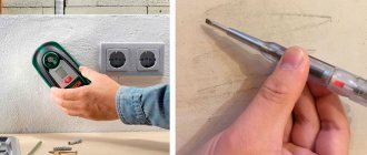
To search for an electrical route, you can use homemade or professional devices, which were described above.
Determining the distance to the location of cable damage underground
Determining the distance to the defect is carried out using one of two methods - reflectometric (using reflectometers) and bridge (using cable bridges). These methods have significant differences.
Cable bridges localize damage based on cable resistance and capacitance. During the measurement, they use auxiliary (known good) conductors or cable pairs, which allows them to measure the resistance (capacitance) of the good pair, compare these readings with similar values on the damaged pair and determine the distance to the defect. During measurements, they most often use a voltage of 180V - 500V, which makes it possible to determine even minor damage to the cable insulation.
Cable reflectometers send a pulse with an amplitude of approximately 20V to the pair (the pulse width is adjusted depending on the length of the line) and the type of damage and the distance to it are determined by the shape and delay of the pulses reflected from inhomogeneities (defects). This method will not allow you to detect minor insulation damage, but it will easily detect mixed-up pairs, parallel taps, Pupin coils, etc.
To increase efficiency, these methods are increasingly being combined in one device. In this version, for example, the IRK-PRO Alfa and KB Svyaz Sova devices are presented. The SideKick Plus and Riser Bond 6000DSL analyzers described above also have such functions.
It should be noted that the accuracy of determining the distance to a defect by the device and the accuracy of localizing damage in the cable are different things. After all, the measured distance still needs to be accurately measured, and this is a very difficult task, taking into account the cable reserves on the couplings, the unevenness of the cable depth, etc. In addition, a large error is introduced by inaccurately entered linear values of resistance and capacitance or the propagation coefficient (and they constantly change during operation).
Laying open electrical networks
Repair work associated with a break in a hidden wiring usually requires complex construction and repair work: dismantling the finish, gating the walls, followed by sealing and covering a section of the wall with decorative materials.
Eliminating a broken hidden wire often requires dismantling the finishing, so it is advisable to combine such work with a major renovation of the premises
Since immediate implementation of such manipulations is not always possible, in some cases it can be recommended to lay a new wire along the surface of the wall, covering it in a special box or tube.
You will become familiar with a detailed description of the rules and technology for laying an open electrical network by reading our recommended article.
Localization of damage on the ground
Once the approximate distance to the fault is known, a locator or cable locator generator is connected to the damaged pair and cable tracing begins. It is better to start tracing and searching for a defect in a damaged cable at a distance of 200-300 meters from the defect location determined by a cable bridge or reflectometer, from the nearest coupling, cable box or other place whose location is precisely known. Moreover, if the tracing starts from a cable cabinet or box, the generator must be installed in this place.
Tracing and localization of defects can be done in parallel or sequentially. In the first case, the route is first “beaten” using a locator, after which the damage is located using a cable locator. In the second case, tracing and localization of damage is carried out simultaneously: one specialist traces the line, the other - localizes the damage. For such cases, there are devices with one generator but two receivers, for example Search-310D-2M (2). There are also devices that combine not only means of searching and localizing damage, but also means of preliminary diagnostics and determining the distance to damage. Among them, we can highlight the ToneRanger device from Greenlee. Its advantages include:
- High accuracy of damage localization
- No dependence of diagnostic results on the length and temperature of the cable, the difference in the cross-section of the cores of different sections, the number of sections, the presence of water in the cable and couplings
- Measuring parameters such as:
- Insulation resistance
- Loop resistance
- Capacity
- Determining the distance to damage
- Localization of damage:
- Reduced insulation resistance
- Short circuit
- Break
- Confused couples
- Cable pair identification
- During measurements, it does not affect the transmission of information in adjacent DSL lines
- All-weather vibration and shock resistant design
Cable routing is described in detail in the section “Routing and identification of utilities (cables, pipelines, etc.)”, so we will not dwell on it here. Already during tracing, it is possible to localize some cable damage, such as a break or short circuit of a pair.
Localization of damage to cable insulation, as mentioned above, is carried out using a cable locator. Its components are contact pins (or, as shown in the figure, an A-frame) and a signal generator.
The generator is connected to the line and supplies high voltage pulses to it. Localization is done using contact pins or an A-frame with indicators. The A-frame consists of two contact pins connected to each other, measuring the potential difference at a point, finding where the current leaks into the ground. The leak point is determined after disconnecting the cable from the standard ground. A grounded generator is connected to the screen or core of the cable, creating conditions for the return of the “drained” current through the least resistance. The contact pins or A-frame are moved parallel to the cable line (above it), in the direction of the suspected damage, periodically sticking it into the ground, checking the indicator readings.
Depending on the location of the defect in relation to the A-frame (contact pins) and the generator, the voltmeter readings fluctuate to the right or left of zero (plus and minus, respectively). A shift of the indicator to a plus scale indicates that the cable damage is located between the A-frame and the end of the cable, and a shift to minus indicates that the device is between the generator and the A-frame. By moving the A-frame towards the damage, the location at which the indicator will show the opposite direction is determined. Having turned the frame 90 degrees, moving towards the defect, you need to find the next point at which the indicator will show the opposite direction. If the arrow is in the middle of “0”, this means that the insulation damage is located directly between the points of contact with the ground (A-frames). This point is the search target.
When localizing damage, the receiver readings may vary depending on the depth of the cable, heterogeneity of the soil (dry or wet, sand or clay) and the presence of metal objects directly near the line. In order not to be distracted by searching for such “problems”, you need to consider the following:
- near the damage, the indicator readings change sharply at one point;
- the value of the maximum indicator readings should be correlated with the value of damage resistance;
- Leakage can be checked “to a minimum” by inserting the pins at a greater distance from each other (if there are several damages nearby, this method is not suitable).
Causes of malfunctions
If the operating rules for electrical communications are observed, they can serve regularly for decades. But in practice, damage to electrical networks is quite common, which can be caused by various reasons.
These factors include:
- Long-term operation of the cable . Wiring can function flawlessly for many years, but after a certain time limit it begins to deteriorate. In this case, twists scatter in the network and leaks appear, which regularly knock out the RCD (its absence affects the increase in leaks). Sooner or later, such violations lead to interruptions, and then to a complete cessation of the power supply.
- Mechanical damage . Without knowing the layout of electrical networks, when drilling holes and driving nails into the wall, you can easily touch a wire, causing it to break and sometimes short circuit. Sometimes minor mechanical damage has a delayed effect: in this case, the integrity of the core may not be damaged immediately, but after several months or even a year.
- Defective wire or poorly executed electrical installation . Damaged cables tend to become constantly hot, which can have fatal consequences. After a sudden power surge, such wires may break.
- Incorrect use of adapters . Electrical wiring malfunctions can be caused by improper use of extension cords or tees. This can happen if several high-power household appliances are connected to the device, for example, a washing machine and dishwasher.
If the adapter is used incorrectly, the cables that come from it are subject to overheating and increased stress, which can lead to melting of the insulation.
In all cases, it is necessary to identify the location of the cable damage in order to immediately repair the damage.
The most common failures of extension cords
Conventionally, all extension cord breakdowns can be divided into three areas based on localization:
- Faulty wire (cable) . Fractures and wire burnouts.
- Plug malfunction. The studs are loose, the wire at the connection to the contact burns out.
- There is a fault in the contact block. The plate burns out (rarely) or the contacts become loose.
Most often, the wire breaks or burns out at the connection to the plug or at the entrance to the socket block. This fault can be easily identified even visually and repaired. It’s worse when the damage is somewhere inside the wire under the insulation, and it’s not visible visually. If you have a long (10 m or more) coil or simple extension cord, then it’s a pity to throw away the wire, so it’s better to strain yourself and repair it.
Using an ordinary Chinese extension cord as an example, we will show how all these faults can be repaired. They just took what was at hand - of course, for 200 rubles. You shouldn’t waste a lot of time, but if you have a good extension cord of 30 meters, it’s frankly a shame to throw it away.
General principle
The potential difference is created by distributed currents flowing in the soil volume, which in turn are induced by the electromagnetic field around the communication or arise as leakage currents in the MP insulation, where a galvanic connection with the soil is formed. Direct current and alternating current of high frequency (sound range) are used. The magnitude of the measured voltage and the nature of its change along the communication are informative parameters for MF localization. The operator moves along a track with two contact rods or plates (A-frame). In the first case, the potential difference is directly measured, in the second - through the capacitance of the plates. The plates are used for asphalt concrete pavements on the KL highway. Current is supplied to the damaged core from the end of the cable line. The A-frame (AR-500), developed by , is used in conjunction with the PP-500A Search Receiver from the Search Kits.
conclusions
Finding a broken wire is a rather difficult and serious matter that requires certain skills and knowledge.
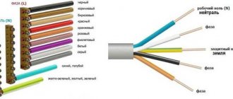
To quickly find the location of a damaged electrical wire, you need to know the layout of electrical communications. You can use logic to determine the area where an accident could have occurred. Find the exact location of the break, possibly using homemade or professional devices. You should find out which wire has burned out: phase or neutral, using the recommendations given in the article.
Using the information obtained, you can easily not only find the damaged wire and restore it, but also prevent a similar breakdown in the future.
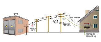
Elimination of broken neutral and phase wires
Breakage of the neutral wire
Elimination of the phase conductive core proceeds according to the following algorithm:
- The phase wire is de-energized.
- Using construction tools, finishing materials are removed from the surface of the walls. It is important to clear the area near the power line by 10-15 cm.
- The damaged core is separated from the network. It is important not to touch the insulating material on other adjacent cables.
- It is preferable to connect copper conductors by soldering. It is also recommended to use heat shrink or PVC tubing when restoring.
If the neutral cable has been damaged, it must be disconnected from the bus and a phase conductor must be attached in its place. Further, the algorithm is identical to the restoration of the phase wire.
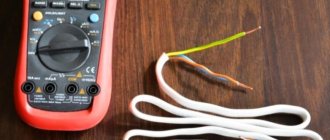
How to work with a tester
To use a multimeter, you need to know how it works. They can determine a short circuit, a broken wire in the wall, as well as the integrity of the insulation. Knowing the wiring diagram in the apartment, you can localize the damage and eliminate it. An inexpensive tester is an effective locator of a wiring break.
In order to use the multimeter, you need to remember the switch positions on the front panel. To search for a break, you will need resistance measurement or continuity testing modes (see figure).
Let's consider an example when the lighting in one of the rooms went out. There can be three types of faults:
- the switch has failed;
- the contact has disappeared at the place where the wires are connected to the switch;
- The conductor hidden in the gate broke.
All of them can be checked with a multimeter. In this case, it is necessary to follow the sequence of actions.
- It is necessary to de-energize the wiring in the apartment by turning off the circuit breakers in the electrical panel.
- How to check the switch? Having disconnected the wires from it, we check the resistance between its terminals. In one position of the switch the display should show 1 (open), and in the other - 0 (short circuit). If so, it means the switch is working. If there is a break in both positions, a new one is installed.
- We check whether there is voltage in the cable cores that supplies electricity to the junction box. Before checking, you need to put crocodiles on the ends of the probes, select the alternating voltage (ACV) measurement mode with a range above 200 V.
- Carefully connect the probes to the conductors one at a time. In order not to provoke a short circuit and not to suffer from electricity yourself, the ends of the wires should be placed as far from each other as possible.
- Electricity is reconnected to the wires. If a value greater than 200 appears on the display, it means the wiring is OK. If 0, you will have to look for an open circuit in the circuit going from the electrical panel to the distribution box.
All that remains is to check the hidden cable running from the junction box to the switch. How to find a broken wire in a wall?
- The electricity goes out.
- The tester operating mode switches to dialing.
- One of the probes is connected with a crocodile to one end of the cable core. Another probe goes to another cable core.
- In the distribution box, both wires being tested are connected, forming a closed circuit.
- If the cable is not broken, a sound signal will sound. If there is no signal, one of the wires is broken.
Damage to cable lines: methods and methods of detection
Most large electrical connections between energy consumers and sources are made using cable lines. Most often this is a system of cables, couplings and fasteners parallel to each other. Damage, even to the smallest extent, is fraught with at least economic losses.
Most common damage
Cable lines can be laid underground or above ground. In this case, the nature of their damage will be similar. Most often the following happens:
- one or more cores may be damaged. In this case, the circuit is made to the ground;
- several wires are damaged with a short circuit to each other;
- grounding cable break;
- gap without grounding;
- the occurrence of a so-called “floating breakdown”, when a short circuit occurs when the voltage increases, after normalization the situation stabilizes;
- the integrity of the insulating layer is damaged.
Any damage requires immediate repair. As power supply patterns are disrupted, the reliability of the entire power supply to end users is called into question. This also affects the technical and economic indicators of the entire network as a whole.
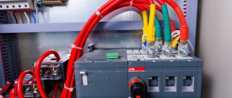
The photo shows that we are dealing with a low-Ohm breakdown; such a place of damage is the easiest to find.
The causes of damage may be:
- In different seasons, soil movement occurs. For example, in the spring, as a result of sudden thawing of individual sections, the lines may experience excessive tension, which leads to rupture;
- violation of supply conditions, in particular overcurrent;
- violations in line laying technology;
- work near lines that violate boundaries;
- lines may be exposed to transit currents.