Definition and classification
Electrical engineering is now divided into a wide range of subfields, including electronics, digital computers, computer engineering, energy, telecommunications, control systems, robotics, radio frequency engineering, signal processing, instrumentation, and microelectronics. The development of electrical engineering in our time stimulates the emergence of new types of instruments and devices.
You may be interested in: In “call” the accent will not cause problems. How about “let’s call you”?
Story
Early experiments with electricity included primitive batteries and static charges. However, the actual design, construction and manufacture of useful devices and systems began with the implementation of Michael Faraday's Law of Induction, which essentially states that the voltage in a circuit is proportional to the rate of change of the magnetic field through the circuit. This law applies to the basic principles of the electric generator, electric motor and transformer. The advent of the modern era was marked by the introduction of electricity into homes, businesses and industry. All this was made possible thanks to electrical engineering.
You may be interested in: Momentum of a particle and a mechanical system - definition and features
The list of the most famous pioneers in electrical engineering includes Thomas Edison (light bulb), George Westinghouse (alternating current), Nikola Tesla (induction motor), Guglielmo Marconi (radio), and Philo T. Farnsworth (television). These innovators turned ideas and concepts related to electricity into practical devices and systems that ushered in the modern age.
Since its inception, the field of electrical engineering has grown and branched into a number of specialized categories, including power generation and transmission systems, motors, batteries, and control systems. Electrical engineering also includes electronics, which itself branches into even more subcategories such as radio frequency (RF) systems, telecommunications, remote sensing, signal processing, digital circuits, instrumentation, audio, video, and optoelectronics.
Modern electrical engineering began with the invention of the diode tube thermionic vacuum tube in 1904 by John Ambrose Fleming. The vacuum tube basically acts as a current amplifier, outputting a multiple of its input current. It was the basis of all electronics, including radio, television and radar, until the mid-20th century. This was largely superseded by the transistor, which was developed in 1947 at AT&T's Bell Laboratories by William Shockley, John Bardeen and Walter Bratten, for which they received the 1956 Nobel Prize in Physics. Even then, the broad masses of the population had an idea of what electrical engineering was.
Topic No. 4. General issues of electrical engineering
DEFINITION AND MEANING OF ELECTRICAL ENGINEERING.
Electrical engineering is a field of science and technology that studies electrical and magnetic phenomena and their use for practical purposes.
Electrical engineering is one of the most important general professional disciplines that develops in students practical skills in using the laws of electrical circuit theory when solving specific technical problems, and introduces students to specific examples of the widespread use of various techniques for idealizing the phenomena and processes being studied, which are inevitable in the calculation and analysis of complex information transmission systems, measurement, control and automatic control.
To successfully study electrical engineering, knowledge of modern physical concepts about electromagnetic phenomena and electric current in various media is required. The fundamentals of methods for calculating electrical circuits are based on knowledge of the relevant branches of higher mathematics with the widespread use of computer technology.
Goals and objectives of the discipline:
— formation of clear ideas about the fundamental principles of electrical engineering, based on the laws of electricity and magnetism and defining the most important properties and methods of analysis and calculation of linear and nonlinear electrical circuits;
— training in the basics of analytical and numerical methods for calculating and analyzing equivalent circuits of linear electrical circuits with sources of direct, sinusoidal and pulsed currents and voltages in steady-state and transient modes;
— familiarization with the features and methods of analysis and calculation of equivalent circuits of electrical circuits containing linear elements;
— optimization of the conditions for achieving the goals of teaching the discipline, based on taking into account human resources, material support, experience and traditions of the supporting department and the level of mathematical and physical training of students.
— identification of the most important properties and characteristics of electrical circuits and electromagnetic devices, development of skills in measuring electrical quantities, processing experimental results and their analysis.
The objectives are:
— study of the general fundamentals of electrical engineering, the formation of clear ideas about the fundamental principles of electrical engineering, based on the laws of electricity and magnetism and defining the most important properties and methods of analysis and calculation of linear and nonlinear electrical circuits.
The phenomena now called electrical were first noticed in ancient China, India, and later in ancient Greece. Surviving legends say that the ancient Greek philosopher Thales of Miletus (640-550 BC) already knew the property of amber, rubbed with fur or wool, to attract scraps of paper, fluff and other light bodies. From the Greek name for amber - “electron” - this phenomenon later received the name electrification.
For many centuries, electrical phenomena were considered manifestations of divine power, until in the 17th century. Scientists have not come close to studying electricity. Coulomb, Gilbert, Otto von Guericke, Muschenbreck, Franklin, Oersted, Arago, Lomonosov, Luigi Galvani, Alessandro Volta - this is not a complete list of scientists who dealt with the problems of electricity.
The discoveries of Oersted, Arago, and Ampere interested the brilliant English physicist Michael Faraday and prompted him to study the whole range of questions about the transformation of electrical and magnetic energy into mechanical energy. Another English physicist, James Clerk (Clark) Maxwell, published a major two-volume work, “Treatise on Electricity and Magnetism,” in 1873, which combined the concepts of electricity, magnetism and electromagnetic field. From that moment on, the era of active use of electrical energy in everyday life began.
The emergence of electrical engineering was preceded by a long period of accumulation of knowledge about electricity and magnetism, during which only isolated attempts were made to use electricity in medicine, as well as for signal transmission. In the XVII-XVIII centuries. The works of M. V. Lomonosov, G. V. Richman, B. Franklin, S. O. Coulomb, and others were devoted to the study of the nature of electrical phenomena.
For the development of electrical engineering, the appearance of the first source of continuous current - a voltaic column (A. Volta, 1800), and then more advanced galvanic elements, which made it possible in the 1st third of the 19th century, was decisive. conduct numerous studies of chemical, thermal, light and magnetic phenomena caused by electric current (works of V.V. Petrov, H.K. Oersted, D.F. Arago, M. Faraday, J. Henry, A.M. Amper, G. S. Oma and others). During this period, the foundations of electrodynamics were laid, the most important law of an electrical circuit was discovered - Ohm's law.
Among the attempts to practically use the results of these achievements, the most significant were works in telegraphy (electromagnetic telegraph by P. L. Schilling, 1832), in military affairs (galvanic shock sea mines by B. S. Jacobi, 1840s). The discovery of electromagnetic induction (1831-32) predetermined the emergence of electrical machines - motors and generators.
Since all the first consumers of electricity used direct current (as the most studied), the first electric machines were direct current machines. Historically, electric motors began to be created earlier than electric machine generators, because in the 1st third of the 19th century. galvanic cells as current sources more or less satisfied the requirements of practice.
The period of improvement of electric motor design - from laboratory instruments that demonstrated the possibility of converting electrical energy into mechanical energy (Faraday's installation, 1821) to industrial machines - covers approximately 50 years. In the first electric motors, the moving part performed a reciprocating or rocking motion, and the torque on the motor shaft was pulsating (for example, in the Henry engine). Since the mid-30s. XIX century engines with a rotating armature began to be built.
Such an electric motor that received practical application was the motor developed by Jacobi (1834–38). Testing of this engine, which drove the “electric boat,” showed, on the one hand, the fundamental possibility of its practical application, and on the other, the need to create a more economical source of electricity compared to galvanic elements. Such a source was an electric machine generator, the prototype of which was Faraday’s unipolar machine (1831).
The first practically suitable electric machine generators were magnetoelectric generators, in which the magnetic field was created by permanent magnets, and massive inductive coils served as armatures (Jacobi, 1842). In 1851, the German scientist W. Sinsteden proposed replacing permanent magnets with electromagnets, the coils of which were powered by independent magnetoelectric generators.
Further improvement of the design of an electric machine generator is associated with the use of current from the generator itself to excite the electromagnet winding. Industrial production of generators began in 1870 in Paris after Z. T. Gramm first used a ring-laminated armature in a self-excited generator, the fundamental design of which was proposed for an electric motor in 1860 by A. Pacinotti. Gram's generator worked not only in the generator mode, but also in the motor mode, which marked the beginning of the practical implementation of the principle of reversibility of electric machines (discovered by E. H. Lenz, 1832-38) and made it possible to significantly expand the scope of use of electric machines.
Subsequent improvement of DC machines followed the path of improving their structural elements - replacing the ring armature with a drum one (F. Höfner-Alteneck, 1873), improving laminated armatures (American inventor H. Maxim, 1880), introducing a compensation winding (1884), additional poles ( 1885), etc. By the 80s. XIX century DC electric machines have acquired the basic design features of modern machines. Their improvement was facilitated by the discovery of the law on the direction of induced currents, the discovery and study of back emf (Jacobi, 1840) and armature reaction (Lenz, 1847), the development of methods for calculating electrical circuits (G. R. Kirchhoff, 1847) and magnetic circuits (English scientist J. Hopkinson, early 80s), study of the magnetic properties of iron (A.G. Stoletov, 1871), etc. By the end of the 70s. include the works of J.C. Maxwell, who formulated the equations that are the basis of the modern doctrine of the electromagnetic field.
The creation of reliable current sources has made it possible to meet the increased needs for electrical energy for practical purposes. The further development of electrical engineering is associated with the emergence of the electrical industry and the massive spread of electric lighting, which in the 50-70s. XIX century replaced the gas one. The idea of using electrical energy for lighting was expressed by Petrov in 1802 after the discovery of the electric arc. The first electric light sources were a variety of arc coal lamps, among which the cheapest and simplest was the “Yablochkov candle” (P.N. Yablochkov, 1876). In 1870-75, A. N. Lodygin developed several types of incandescent lamps, which were later improved by T. A. Edison and became widespread by the 90s. XIX century Advances in the creation and use of electric light sources have had a significant impact on the formation and development of lighting technology. The spread of electric lighting is associated with the creation of electrical power systems. Already in the first lighting devices of Yablochkov there were all the main elements of power systems: the prime mover,
generator, power line, transformer, energy receiver. The use of electricity for technological purposes began with the work of Jacobi (1838), who proposed using electric current to produce metal copies and to apply metal coatings.
But expansion of the field of practical use of electrical energy became possible only in the 70-80s. XIX century with a solution to the problem of transmitting electricity over a distance. In 1874, F. A. Pirotsky came to the conclusion about the economic feasibility of producing electricity in places where there are cheap fuel or hydropower resources, with its subsequent transfer to the consumer. In 1880-81, D. A. Lachinov and M. Depres independently proposed using high voltage current to reduce electricity losses in power transmission lines (PTLs). The first direct current power transmission line was built by Despres in 1882 between the cities of Miesbach and Munich (line length 57 km, voltage 1.5-2 kV). However, attempts to carry out power transmission using direct current turned out to be ineffective, because, on the one hand, the technical capabilities of obtaining high-voltage direct current were limited, and on the other hand, its consumption was difficult.
Therefore, along with the use of direct current for electricity transmission, work was carried out on the use of single-phase alternating current for the same purposes, the voltage of which could be changed (increased and decreased) using a single-phase transformer. The creation of an industrial type of such a transformer (O. Blati, M. Deri, K. Tsipernovsky, 1885, etc.) essentially solved the problem of transmitting electricity. However, the widespread use of single-phase alternating current in industry was impossible due to the fact that single-phase electric motors did not meet the requirements of an industrial electric drive, and therefore the use of single-phase alternating current was limited only to electric lighting installations.
In the 70-80s. XIX century Electricity began to be used in technological processes: in the production of aluminum, copper, zinc, high-quality steels: for cutting and welding metals; strengthening of parts during heat treatment, etc. In 1878, Siemens created an industrial design for an electric melting furnace. Electric arc welding methods were proposed by N. N. Benardos (1885) and N. G. Slavyanov (1891).
By the end of the 70s. Also include the first attempts to use electricity in transport, when Pirotsky tested a carriage on which an electric traction motor was installed. In 1879, Siemens built an experimental electric railway in Berlin. In the 80s tram lines were opened in many cities in Western Europe, and then in America (USA). In Russia, the first tram was launched in Kyiv in 1892. In the 90s. Electric traction was also used on underground railways (in 1890 in the London Underground, in 1896 in Budapest), and then on mainline railways.
At the end of the 19th century. The industrial use of electricity has become the most important complex technical and economic problem - along with economical power transmission, it was necessary to have an electric motor that meets the requirements of the electric drive. The solution to this problem became possible after the creation of multiphase, in particular three-phase, alternating current systems. Many engineers and scientists worked on this problem, but he proposed a comprehensive solution in the late 80s. M. O. Dolivo-Dobrovolsky, who developed a number of industrial designs of three-phase asynchronous motors, three-phase transformers, and in 1891 built a three-phase power transmission line Laufen - Frankfurt (line length 170 km).
Electricity is a concept that expresses properties and phenomena caused by the structure of physical bodies and processes, the essence of which is the movement and interaction of microscopic charged particles of matter (electrons, ions, molecules, their complexes, etc.).
Gilbert was the first to discover that electrification properties are inherent not only in amber, but also in diamond, sulfur, and resin. He also noticed that some bodies
for example, metals, stones, bone, are not electrified, and divided all bodies found in nature, electrified and non-electrified. Paying special attention to the former, he carried out experiments to study their properties.
In 1650, the famous German scientist, burgomaster of the city of Magdeburg, inventor of the air pump, Otto von Guericke, built a special “electric machine”, which was a ball of sulfur the size of a child’s head, mounted on an axle.
If, while rotating the ball, it was rubbed with the palms of the hands, it soon acquired the property of attracting and repelling light bodies. Over the course of several centuries, Guericke's machine was significantly improved by the Englishman Hoxby, the German scientists Bose, Winkler and others. Experiments with these machines led to a number of important discoveries:
in 1707, the French physicist du Fay discovered the difference between the electricity obtained from the friction of a glass ball and that obtained from the friction of a tree resin steeple;
in 1729, the Englishmen Gray and Wheeler discovered the ability of some bodies to conduct electricity and for the first time indicated that all bodies can be divided into conductors and non-conductors of electricity.
But a much more important discovery was described in 1729 by Muschenbrek, a professor of mathematics and philosophy in the city of Leiden. He discovered that a glass jar, lined on both sides with tin foil (sheets of staniol), is capable of storing electricity. Charged to a certain potential (the concept of which appeared much later), this device could be discharged with a significant effect - a large spark that produced a strong crackling sound, similar to a lightning bolt, and had physiological effects when the hands touched the linings of the can. From the name of the city where the experiments were carried out, the device created by Muschenbrek was called the Leyden jar.
Studies of its properties were carried out in various countries and gave rise to many theories trying to explain the discovered phenomenon of charge condensation. One of the theories of this phenomenon was given by the outstanding American scientist and public figure Benjamin Franklin, who pointed out the existence of positive and negative electricity. From the point of view of this theory, Franklin explained the process of charging and discharging a Leyden jar and proved that its plates can be arbitrarily electrified with electric charges of different signs.
Franklin, like the Russian scientists M.V. Lomonosov and G. Richman, paid a lot of attention to the study of atmospheric electricity and lightning. As you know, Richman died while conducting an experiment to study lightning. In 1752, Benjamin Franklin invented the lightning rod. A lightning rod (in everyday life the more euphonious “lightning rod” is also used) is a device installed on buildings and structures and serves to protect against lightning strikes. Consists of three interconnected parts:
lightning rod - serves to receive a lightning discharge and is located in the area of possible contact with the lightning channel; depending on the protected object, it can be a metal pin, a network of conductive material or a metal cable, a grounding conductor stretched over the protected object or a down conductor - a conductor that serves to divert charge from the lightning rod to the ground electrode; Usually it is a wire of a sufficiently large cross-section; a grounding conductor is a conductor or several interconnected conductors that are in contact with the ground; Usually it is a metal plate buried in the ground.
In 1785, C. Coulomb discovered the fundamental law of electrostatics. Based on numerous experiments, Coulomb established the following law:
The force of interaction between stationary charges located in a vacuum is directly proportional to the product of the charge modules and inversely proportional to the square of the distance between them.
In 1799, the first source of electric current was created - a galvanic cell and a battery of cells. A galvanic cell (chemical current source) is a device that allows you to convert the energy of a chemical reaction into electrical work. Based on the principle of operation, there are primary (disposable), secondary (batteries) and fuel cells. The galvanic cell consists of an ion-conducting electrolyte and two dissimilar electrodes (half-cells); the processes of oxidation and reduction in the galvanic cell are spatially separated. The positive pole of a galvanic cell is called the cathode, the negative pole is called the anode. Electrons leave the cell through the anode and move in an external circuit to the cathode.
The works of Russian academicians Epinus, Kraft and others revealed a number of very important properties of electric charge, but they all studied electricity in a stationary state or its instantaneous discharge, that is, the properties of static electricity. Its movement manifested itself only in the form of a discharge. Nothing was yet known about electric current, that is, about the continuous movement of electricity.
One of the first to deeply study the properties of electric current in 1801-1802 was St. Petersburg academician V.V. Petrov. The work of this outstanding scientist, who built the largest battery in the world in those years from 4200 copper and zinc circles, established the possibility of practical use of electric current to heat conductors. In addition, Petrov observed the phenomenon of an electric discharge between the ends of slightly diluted coals both in air and in other gases and vacuum, which was called an electric arc. V.V. Petrov not only described the phenomenon he discovered, but also pointed out the possibility of using it for lighting or melting metals, and thereby for the first time expressed the idea of the practical use of electric current. From this moment the history of electrical engineering as an independent branch of technology should begin.
Experiments with electric current attracted the attention of many scientists from different countries. In 1802, the Italian scientist Romagnosi discovered the deflection of a magnetic needle under the influence of an electric current flowing through a nearby conductor. At the end of 1819, this phenomenon was again observed by the Danish physicist Oersted, who in March 1820 published a pamphlet in Latin entitled “Experiments Concerning the Effect of Electric Conflict on the Magnetic Needle.” In this work, “electric conflict” was called electric current.
As soon as Arago demonstrated Oersted's experiment at a meeting of the Paris Academy of Sciences, Ampère, repeating it, on September 18, 1820, exactly a week later, presented a report on his research to the Academy. At the next meeting, on September 25, Ampere finished reading a report in which he outlined the laws of interaction of two currents flowing through parallel conductors. From that moment on, the Academy listened weekly to new messages from Ampere about his experiments that completed the discovery and formulation of the basic laws of electrodynamics. One of Ampere’s most important achievements was that he was the first to combine two previously separated phenomena - electricity and magnetism - with one theory of electromagnetism and proposed to consider them as the result of a single natural process.
This theory, greeted by Ampere's contemporaries with great distrust, was very progressive and played a huge role in the correct understanding of later discovered phenomena.
In 1827, the German scientist Georg Ohm discovered one of the fundamental laws of electricity, which establishes the basic relationships between current strength, voltage and resistance of the circuit through which electric current flows.
Conclusion on the issue: Electrical engineering is one of the most important general professional disciplines that develops in students practical skills in using the laws of electrical circuit theory when solving specific technical problems.
REGULATIVE DOCUMENTS DETERMINING REQUIREMENTS FOR ELECTRICAL INSTALLATIONS.
Electrical installations must be installed and operated in accordance with the Rules for the Construction of Electrical Installations (PUE), the Rules for the Operation of Consumer Electrical Installations (RUES), the Safety Rules for the Operation of Consumer Electrical Installations (PTB) and other regulatory documents, which mean standards, building codes and regulations, technological standards design, industry and regional fire safety rules and other duly approved regulatory documents regulating the fire safety requirements of electrical installations. At the same time, industry and regional fire safety rules, as well as other normative documents approved in accordance with the established procedure, should not reduce the requirements of PUE, PEEP and PTB during the operation of electrical installations
Electrical installation rules:
The requirements of the Electrical Installation Rules are mandatory for all organizations, regardless of ownership and organizational and legal forms, as well as for individuals engaged in entrepreneurial activities without forming a legal entity. Rules for the construction of electrical installations (PUE) apply to newly constructed and reconstructed electrical installations of direct and alternating current with voltage up to 750 kV, including special electrical installations. Electrical equipment, electrical products and materials used in electrical installations must comply with the requirements of state standards or technical specifications approved in the prescribed manner. The design, design, installation method, class and insulation characteristics of the machines, devices, instruments and other electrical equipment used, as well as cables and wires, must comply with the parameters of the network or electrical installation, operating modes, environmental conditions and the requirements of the relevant chapters of the PUE.
Rules for technical operation of consumer electrical installations
The rules are intended to ensure reliable, safe and rational operation of electrical installations and their maintenance in good condition.
The rules apply to organizations, regardless of ownership and legal forms, individual entrepreneurs and citizens - owners of electrical installations with voltages above 1000 V (hereinafter referred to as Consumers). They include requirements for Consumers operating existing electrical installations with voltages up to 220 kV inclusive. The rules do not apply to electrical installations of power stations, block stations, electrical and heat network enterprises operated in accordance with the rules for the technical operation of power stations and networks.
Interindustry rules on labor protection (safety rules) during the operation of electrical installations apply to employees of organizations, regardless of ownership and organizational and legal forms, and other individuals engaged in the maintenance of electrical installations, carrying out operational switching in them, organizing and performing construction, installation, commissioning, repair work, testing and measurements.
The employer, depending on local conditions, may provide additional labor safety measures that do not contradict these Rules. These safety measures must be included in the relevant labor protection instructions and communicated to personnel in the form of orders, instructions, and briefings.
Electrical installations must be in technically sound condition, ensuring safe working conditions.
Electrical installations must be equipped with tested, ready-to-use protective equipment, as well as first aid equipment in accordance with current rules and regulations.
Organizations must exercise control over compliance with these Rules, the requirements of labor protection instructions, and control over the conduct of briefings. Responsibility for the state of labor protection in the organization lies with the employer, who has the right to transfer his rights and functions on this issue to the managerial employee of the organization by administrative document
It is not allowed to carry out orders and tasks that contradict the requirements of these Rules.
Employees guilty of violating the requirements of these Rules will be held accountable in the prescribed manner.
Conclusion on the issue: Electrical installations must be in technically sound condition, ensuring safe working conditions, in accordance with all regulatory documents.
BASIC TERMS AND DEFINITIONS.
Each science has its own terminology. Let's remember the terms and concepts of electrical engineering.
An electrical circuit is a set of devices designed to produce, transmit, transform and use electric current.
All electrical devices according to their purpose, principle of operation and design can be divided into three large groups.
Energy sources, i.e. devices that produce electric current (generators, thermoelements, photocells, chemical elements).
Receivers, or load, i.e. devices that consume electric current (electric motors, electric lamps, electrical mechanisms, etc.).
Conductors, as well as various switching equipment (switches, relays, contactors, etc.).
The directed movement of electric charges is called electric current. Electric current can occur in a closed electrical circuit. Electric current, the direction and magnitude of which are constant, is called direct current and is denoted by the capital letter I.
Electric current, the magnitude and direction of which does not remain constant, is called alternating current. The value of the alternating current at the considered moment in time is called instantaneous and is denoted by the lowercase letter i.
For an electrical circuit to operate, it is necessary to have energy sources. In any source, due to external forces of non-electric origin, an electromotive force is created. A potential difference or voltage arises at the source terminals, under the influence of which an electric current arises in the external part of the circuit connected to the source.
There are active and passive circuits, sections and elements of circuits. Active circuits are electrical circuits that contain energy sources, while passive circuits are electrical circuits that do not contain energy sources.
Electrical installations are a set of machines, apparatus, lines and auxiliary equipment (together with the structures and premises in which they are installed) intended for the production, transformation, transformation, transmission, distribution of electrical energy and its conversion into another type of energy.
Industrial electrical installations are divided into the following types according to their functional purpose:
generators – generating electrical energy;
voltage converters (transformers), frequency converters – converting electrical energy;
wires, cables – transmitting electrical energy from generation and conversion points to electrical receivers;
distribution substations, units, switchboards, devices that distribute electrical energy;
electric motors, electrothermal, electric welding, electric lighting and others - electrical receivers consuming electrical energy.
All listed electrical installations, according to
Electrical installation rules (PUE) are standardized for voltages up to 1000 V and voltages above 1000 V.
Open or outdoor electrical installations are electrical installations that are not protected by the building from atmospheric influences.
Electrical installations protected only by canopies, mesh fences, etc. are considered external.
Closed or internal electrical installations are electrical installations located inside a building that protects them from atmospheric influences.
Electrical rooms are rooms or fenced off (for example, nets) parts of the room in which electrical equipment is located, accessible only to qualified service personnel.
Conclusion on the issue: Each science has its own terminology.
GENERAL ISSUES OF RECEIPT, DISTRIBUTION, CONVERSION OF ELECTRIC ENERGY.
A feature of the process of production, transmission and consumption of electricity is its continuity. The process of electricity production coincides in time with the process of its consumption, therefore power plants, electrical networks and consumer power receivers are connected by a common mode. The generality of the regime necessitates the organization of energy systems.
An energy system (energy system) is a set of power plants, power transmission lines, substations and heating networks, connected into one by the commonality of the regime and the continuity of the process of production, transformation and distribution of electrical and thermal energy under the general control of this regime. Part of the energy system is the electrical system, which is a set of electrical installations of power plants and electrical networks of the power system.
An electrical network is a set of electrical installations for the transmission and distribution of electrical energy, consisting of substations, switchgears, conductors, overhead and cable power lines operating in a certain territory.
An electrical receiver is a device, unit, mechanism designed to convert electrical energy into another type of energy. Electricity consumer is one or a group of electrical receivers united by a technological process and located in a certain area.
Electrical installations in which electricity is produced, converted, distributed and consumed are divided depending on the operating voltage into electrical installations with voltages up to 1000 and above 1000 V.
A switchgear (RU) is an electrical installation that serves to receive and distribute electricity and contains busbars and connecting busbars, switching devices, protection devices, automation and telemechanics, measuring instruments and auxiliary devices. Distribution devices are divided into open (located in the open air) and closed (in the building). In urban environments, in most cases, closed reactor plants are used.
A substation is an electrical installation used for the conversion and distribution of electrical energy and consisting of switchgear up to and above 1000 V, power transformers or other electricity converters and auxiliary structures.
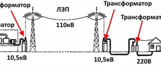
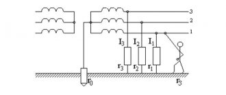
The block diagram of the city's power supply is shown in Fig. 1. State district power station generators produce electricity with a voltage of 6, 10 or 20 kV. At this voltage, transmitting electricity over a long distance (more than 4 - 6 km) is uneconomical. Therefore, in order to reduce power losses in lines, electricity is transmitted over long distances at increased voltage, for which power plants have step-up power transformers that increase the voltage to the design voltage (35, 110, 150, 220, 330, 500, 750 kV). At electrical step-down substations located within the city, the voltage is reduced to 6-10 kV. A step-down substation usually consists of an open part with a voltage of 110 - 220 kV and a closed part, which contains a switchgear with a voltage of 6-10 kV.
What does an electrical engineer do?
Electronics engineers create electrical and electronic equipment such as broadcast and communications systems, from portable music players to global positioning systems (GPS).
If it's a practical, real device that produces, conducts, or uses electricity, in all likelihood it was designed by an electrical engineer. In addition, engineers may conduct or write specifications for destructive or nondestructive testing of the performance, reliability, and durability of devices and components.
Today's electrical engineers design electrical devices and systems using basic components such as conductors, coils, magnets, batteries, switches, resistors, capacitors, inductors, diodes and transistors. Almost all electrical and electronic devices, from the generators in a power plant to the microprocessors in your phone, use these few basic components.
On the nature of electric current and the basics of electrical engineering
In this short article I will try to explain the basics of electrical engineering. For those who don’t understand where the electricity comes from, but it seems indecent to ask.
1. What is electric current. “The chief engineer turned the switch, and the electric current ran faster and faster through the wires” (c)
1.1 A couple of general words on the physics of the issue Electric current is the movement of charged particles. Of the charged particles, we have electrons and some ions. Ions are atoms that have lost or gained one or more electrons and therefore have lost electrical neutrality and have acquired an electrical charge. This is how the atom is electrically neutral - the charge of the positively charged nucleus is compensated by the charge of the electron shell. Ions usually carry charge in electrolytes; in metal wires, the carriers are electrons. Metals conduct current well because some electrons can jump from one atom to another. In non-conducting materials, electrons are tied to their atom and cannot move. (Let me remind you that this article is an explanation of physics at a glance! For more information, search for “electronic conductivity theory”).
We will consider the current in metal conductors, which is created by electrons. An analogy can be drawn between electrons in a conductor and liquid in a water pipe. (At the initial stage, electricity was considered a special liquid.) Just as water does not pour out through the walls of a pipe, electrons cannot leave the conductor, because the positively charged nuclei of atoms will attract them back. Electrons can only move inside a conductor.
1.2 Creation of electric current. But current will not simply arise in the conductor. It's like pouring water into a piece of pipe and sealing it at both ends. The water won't flow anywhere. In a piece of conductor, electrons also cannot move in one direction. If the electrons for some reason move to the right, then an uncompensated positive charge will appear on the left, which will pull them back. Therefore, electrons can only jump from one atom to another and back. But if the pipe is rolled into a ring, then water can already flow along the pipe if it is somehow forced to move. Likewise, the ends of a conductor can be connected to each other, and then electrons can move along the conductor if forced. If the ends of the conductor are connected to each other, then a closed circuit is obtained. Direct current can only flow in a closed circuit. If the circuit is open, then no current flows. A pump is used to force water to flow through the pipe. In the electrical circuit, the role of the pump will be played by the battery. The battery pushes electrons through a conductor and thereby creates an electric current. Scientifically, a battery is called a generator. This is what electrical engineering calls a pump for creating electric current.
There are two types of generators - voltage generator and current generator. This is a fundamental thing in fact, pay attention! See picture below
Fig. 1. Voltage generator of magnitude U Fig. 2. Current generator of magnitude I
The top picture shows a voltage generator, the bottom picture shows a current generator. The voltage generator pump creates a constant pressure, the current generator pump creates a constant flow. The upper circuit is open and the lower circuit is closed. Let's consider what properties a voltage generator has. Let's imagine the following chain
Fig 3. Voltage generator of value U with load R1
In terms of a plumbing analogy, a generator is a pump that creates constant pressure, switch SW1 is a valve that opens/closes a pipe, resistance R1 is a tap/valve that is slightly open. This fender can be covered - the resistance will increase and the water flow will decrease. You can open it more - the resistance will decrease, the water flow will increase. Everything seems to be intuitive. Now imagine that we open the tap more and more. Then the flow of water will increase and increase. In this case, the voltage generator, by definition, maintains the voltage (pressure) constant, regardless of the flow rate! If the tap is opened completely and the resistance becomes 0, then the flow becomes equal to infinity. In this case, the generator will still produce a voltage equal to U! Of course, all this happens in an ideal model, when the generator power is infinite. Real generators (batteries or accumulators) roughly correspond to this model over a certain range of voltages and currents.
Let us now consider a circuit with a current generator.
Fig 4. Current generator of magnitude I with load R2
What does a current generator do? He drives current! He is told to drive a current of magnitude I, and he drives it, regardless of the amount of resistance (how open the tap is). If the tap is fully open, the current will be equal to I. The voltage (pressure) will be equal. If the tap is completely closed, the current will still be equal to I! But in this case, the voltage (pressure) will be equal to infinity. Again in the model. From these considerations, the fundamental law of electrical engineering—Ohm’s Law—follows intuitively. ("From the red line. Underline" (c))
2. Ohm's law.
First from the point of view of the voltage generator
If voltage U is applied to resistance R, then current I =U/R will flow through the resistance. Now from the point of view of the current generator
If current I is passed through resistance R, then a voltage drop U=I*R will occur across the resistance
Somehow you need to realize this moment. These two formulations are completely equivalent and their application depends only on which generator is being considered. You can, of course, also write R=U/I. Something like - if a voltage U is applied to a section of a circuit, and a current I passes through this section, then the circuit has a resistance R. Further, it would be good to consider options for circuits with parallel or series connection of resistors, but there is reluctance. These are purely technical points. Something like
Fig 5. Series connection of resistors
A current of magnitude I passes through this circuit of series-connected resistors R1 and R2. What voltage drop will be across each resistor U1 and U2? Use Ohm's law and that's it! This circuit, by the way, has a current generator, since the input variable here is current. Well, that is, there may not be a current generator itself, it’s just that the current in the circuit is known and is considered constant and equal to I. Therefore, it is as if this current is driven by the current generator. They also say “voltage drop across a resistor”, because the generator “produces” voltage (pressure), and after each resistor the voltage will decrease, drop across this resistor by the amount U=I*R.
Although we will still consider a couple of important practical cases.
1. The most important scheme. The most important circuit that an electronics engineer will deal with constantly throughout his life is the voltage divider. ("From the red line. Underline" (c))
3. Voltage divider The circuit looks like this.
Figure 6. Voltage divider
A voltage divider consists of two resistors connected in series with each other.
By the way, a resistor is an electronic component (part) that provides electrical resistance of a certain value. It is also (the part) often called resistance. It turns out to be a bit of a tautology - resistance has a resistance R. Therefore, for parts it is better to use the name resistor. A resistor with a resistance of 1 kiloohm, for example.
So here it is. What does this circuit do? Two series resistors have some equivalent resistance, let's call it R12. Current I passes through the circuit, from the plus of the generator to the minus through resistor R1 and through resistor R2. In this case, voltage U1=I*R1 drops across resistor R1, and voltage U2=I*R2 drops across resistor R2. According to Ohm's law. Voltage U=U1+U2, as can be seen from the diagram. Thus U=I*R1+I*R2=I*(R1+R2). That is, the equivalent resistance of series-connected resistors is equal to the sum of their resistances. Expression for current I=U/(R1+R2) Let us now find what the voltage U2 is equal to. U2=I*R2= U* R2/(R1+R2).
An example of a picture from the Internet. If the resistors are equal, then the input voltage Uвx is divided in half.
The second important case is taking into account the output resistance of the source (generator) and the input resistance of the receiver (the circuit to which the generator is connected)
Figure 7. Output impedance of the source and input impedance of the receiver.
An ideal voltage generator has zero output resistance, that is, with zero external circuit resistance, the current value will be equal to infinity ∝. A real voltage generator cannot provide infinite current. Therefore, when the external circuit is closed, the current in it will be limited by the internal resistance of the generator, in Fig. indicated by the letter r.
By the way, the correct way to test AA batteries is to measure the current they can deliver. That is, the tester sets the limit to 10A, current measurement mode, and the probes are applied to the battery contacts. A current in the region of 1A or more indicates that the battery is fresh. If the current is less than 0.5A, then you can throw it away. Or try it on a wall clock, maybe it will work for a while.
If the source's output resistance (internal resistance r in the figure) is comparable to the receiver's input resistance (R3 in the figure), then these resistors will act as a voltage divider. In this case, the receiver will not receive the full source voltage U, but U1=U*R3/(r+R3). If this circuit is designed to measure voltage U, then it will lie!
In the following articles it is planned to consider circuits with capacitors and inductors. Then diodes, transistors and operational amplifiers.
Skills
The critical skills required for electrical engineering include a thorough understanding of electrical and electronic theory, mathematics, and materials. This knowledge allows engineers to design circuits to perform specific functions that meet safety, reliability, and power efficiency requirements, and predict how they will behave before the hardware design is implemented.
However, sometimes circuits are built on "breadboards" or prototype circuit boards made on computer numerical control (CNC) computers for testing before they go into service. However, specialists in this field know everything about electrical engineering, and such technical tasks are not something out of the ordinary for them.
Electrical engineers increasingly rely on computer-aided design (CAD) systems to create circuits. They also use computers to simulate how electrical devices and systems will work. Such forecasting can be used for a national power grid or a microprocessor, so knowledge of electronics is important for electrical engineers. In addition to speeding up the process of drawing up printed circuit board diagrams and drawings for electrical and electronic devices, CAD systems allow you to quickly and easily modify designs and quickly create prototypes using CNC machines.
Scientific centers
Professional organizations for electrical engineers include the Institute of Electrical and Electronics Engineers (IEEE) and the Institute of Engineering and Technology (IET). IEEE claims to produce 30% of the world's electrical engineering literature, has more than 360,000 members worldwide, and hosts more than 3,000 conferences annually. People working in these establishments know best what electrical engineering and automation are.
Basic concepts, definitions and laws of electrical engineering
Compiled by I.A. Zaselyaev
LECTURE NOTES
IN THE COURSE "ELECTRICAL ENGINEERING AND ELECTRONICS"
for students of construction specialties
Electrical engineering
is a field of science and technology that studies the theory and practical applications of electricity.
Electronics
is a science that studies the processes occurring with charged particles.
Electrical circuit
- this is a set of elements through which electric current is closed.
The simplest electrical circuit can be represented as a source, a consumer and a line connecting the source and consumer of electric current.
Fig.1. The simplest electric current circuit
All complex electrical devices according to their purpose, operating principle and design can be divided into three large groups:
— energy sources, i.e. devices that produce electric current (generators, thermoelements, photocells, chemical elements); - receivers, or load, i.e. devices that consume electric current (electric motors, electric lamps, electric heaters, etc.); — conductors, as well as various switching equipment (switches, relays, contactors, etc.)
All electrical circuits are divided into linear and nonlinear
. An element of an electrical circuit whose parameters (resistance, etc.) do not depend on the current in it is called linear.
A nonlinear element, such as an incandescent lamp, has a resistance, the value of which increases with increasing voltage, and therefore the current supplied to the lamp.
Electric current
I is the directional movement of charges that occurs in a closed circuit under the action of electromotive force
(EMF)
E of the source (generator).
Electric charges are created by the displacement of electrons. When there is an excess of electrons at one point and a deficiency of electrons at another, there is a potential difference between these points. When there is a conductor between the points, a flow of electrons occurs, called current. The positive direction of current is considered to be the direction opposite to the direction of the flow (drift) of electrons and coinciding with the direction of positive charges - holes
(See Electronics Basics section).
If the magnitude of the electric current does not change over time, then it can be defined as the number of electric charges q passing through the conductor per unit time t , i.e.:
I =q/t ,
(1 ampere = 1 coulomb/sec; coulomb ≈6.28 ∙1018 electrons). Electric current, the direction and magnitude of which are constant, is called constant
current and can be designated by the capital letter I. Electric current, the magnitude and direction of which does not remain constant, is called
alternating current
.
The value of the alternating current at the considered moment in time is called instantaneous and is denoted by the lowercase letter i , the instantaneous value of the current is i=dq/ dt .
When a positive charge moves from one point in the field to another, the electric field does work. The relation of this work is A
to the charge value
q
is called
the voltage
between these points:
U=A/q .
The unit of measurement for voltage is Volt [V]. The concept of voltage can also be derived from the quantitative characteristic of the electric field - potential j. The voltage between two points of the electric field is the potential difference at these points (j1 and j2): .
Electrical diagram
is a graphical representation of an electrical circuit that includes symbols of devices and shows the connection of these devices.
In Fig. Figure 2 shows an electrical diagram of a circuit consisting of an energy source - an active element
and
passive elements
: electric lamps 1 and 2, electric motor 3.
Rice. 2
To facilitate analysis, the electrical circuit is replaced with an equivalent circuit
.
Substitution scheme
is a graphical representation of an electrical circuit using ideal elements, the parameters of which are the parameters of the replaced elements.
Figure 3 shows the equivalent circuit of Fig. 2.
Rice. 3