What is a relay
The definition of a relay is:
A relay is an electromagnetic switching device designed to make and break connections in electrical circuits. The relay is triggered when the input value changes abruptly.
In simple terms, when the input quantity changes (current, voltage), the relay closes or opens the circuit. Moreover, depending on the type of relay, the input quantity is not necessarily of an electrical nature.
The word "relay" comes from the French relay. This concept meant changing post horses or passing the baton.
Application
Voltage current relays are used in situations where there is an overload in the supply environment. As a rule, devices in such networks are divided into two classes: devices with priority, and the category of non-priority devices.
The first type includes devices that are computers, equipment for shooting or storing certain data. As for non-priority devices, this includes additional appliances and household technology products. This circumstance is the main reason for installing a relay, it prevents network overload, and also eliminates its subsequent shutdown.
How does a relay work?
First, let's remember Joseph Henry , whose name is associated with the concept of inductance. The wire through which the current flows is a magnet. If we wind the wire in turns around the core, we get an inductor.
How does an inductor behave in an AC circuit? If the coil is connected to a circuit, then the phase of the current in the circuit will lag behind the voltage. In other words, at the maximum voltage value, the current will be minimum and vice versa.
This is due to the fact that when the coil is connected to the circuit, a self-induced emf , which prevents the main current from growing through the coil.
Now let's get back to the relay. The simplest electromagnetic relay consists of an electromagnet (coil), an armature and connecting elements. When electric current is applied to the coil, it attracts an armature with a contact that completes the circuit.
To imagine all this, let's look at the picture:
Here 1 is the coil, 2 is the armature, 3 is the switching contacts.
The relay has two circuits: control and controlled. The control circuit is the circuit through which current is supplied to the coil. Controlled - a circuit that is closed by the armature when the relay is activated.
Thus, the relay allows you to control large currents in the controlled circuit using a low-current control circuit.
Each relay has contact designations for the controlled and control circuits. Also on the product body are indicated the current and voltage values for which the relay is designed.
The electromagnetic relay discussed above does not work instantly. After applying current to the coil, some time must pass, and only then the relay will operate. This is due to a phenomenon called hysteresis. Hysteresis is translated from Latin as lag or delay.
We have already talked about the self-induction emf that occurs in the coil. When the relay is connected to the circuit, current begins to flow in the coil, but the current strength increases gradually. The increase in current in the coil can be represented as a hysteresis loop. When the required current value is reached, the relay is activated.
For this reason, relays are not used in the fastest operating equipment, where the response time must be reduced to almost zero.
By the way! For our readers there is now a 10% discount on any type of work
Basic requirements for relay protection
Relays and their classification
General issues of relay protection
Lecture No. 1.
During the operation of electrical equipment, damage resulting from insulation breakdown, wire breaks, erroneous actions of personnel and other reasons lead to short circuits (short circuits), accompanied by a decrease in voltage and a high-temperature arc. The duty personnel are not able to note the occurrence of a short circuit in the required short time, identify the damaged element and give a signal to turn off its switches. At the same time, quickly disconnecting a damaged element can significantly reduce the size of damage, and sometimes prevent it. Therefore, electrical installations are equipped with automatically operating devices - relay protection or fuses (the latter mainly in systems with voltages less than 1 kV), which provide protection against damage and some abnormal operating conditions.
Thus, the main purpose of relay protection is to identify the location of the short circuit and quickly disconnect the damaged section of the network.
In addition to damage, violations of normal operating conditions are possible, such as overload, ground fault in networks with an ungrounded neutral, and others that do not pose an immediate danger to the equipment.
The second purpose of relay protection is to detect violations of normal operating modes of equipment and provide warning signals.
At substations without maintenance personnel in such modes, relay protection switches off equipment with a time delay, since violations of normal operating modes are often short-term and can self-correct.
In relay protection technology, the term “relay” in accordance with GOST is understood as an automatically operating device designed, at a given value of the influencing quantity, to produce an abrupt change in the control circuits.
At a certain value of the value ХХС.Р., the output signal Y changes its value; when the relay returns (Х£ХС.Р.), the signal Y takes on its original value (Fig. 1). The most common are electrical relays.
Electrical relays have main functional parts: measuring, logical, actuator, power supply, signaling element, and also, if necessary, the ability to receive signals from the other side of the protected element. Figure 2.4.
Rice. 1. Illustration of relay operation
The methods of performing protection are very diverse. However, all of them are usually built on electrical principles, are carried out in most cases by autonomous devices and generally have two main parts (Fig. 2.4) - measuring and logical. Measuring part
, which includes measuring elements, continuously monitors the state of the protected object and determines the triggering conditions in accordance with the values of the input influencing quantities.
The logical part
, which includes logical organs, generates control actions depending on the combination and sequence of signals received from the measuring part.
Usually the logical part acts on the switches not directly, but through an actuator
.
The measuring part, as a rule, receives information about currents and voltages at the point where the protection is turned on through. primary measuring converters – current and voltage transformers (TA
and
TV).
Relay classification.
1) Depending on the value to which the relay reacts, they are distinguished:
a) electrical relays – react to electrical quantities;
b) mechanical relays - react to mechanical quantities: pressure, gas level;
c) thermal relays - react to changes in temperature or amount of heat.
2) Depending on the action of the relay to increase or decrease the controlled value, relays of maximum and minimum action are distinguished.
a) Maximum action relay
triggers and closes the contacts when the measured value increases above the permissible value. When decreasing, they return to their original position.
b) Minimum action relay
triggers when the electrical value drops below the permissible value. When the measured value increases, it returns to its original state.
The ratio of input and output quantities is called the return coefficient:
,
where is the relay return parameter, is the relay operation parameter.
The minimum action relay has >1, the maximum action relay has <1.
3) By purpose:
a) measuring relays – current, voltage relays;
b) logical operations relay;
c) executive relays.
4) According to the operating principle:
a) static (no moving parts);
b) electromechanical (induction, magnetoelectric, electromagnetic).
5) Electromechanical relays are classified:
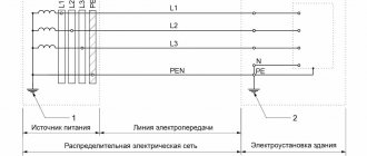
a) according to the method of inclusion of the perceptive organ: primary and secondary (Fig. 3).
Primary relays are directly connected to the circuit.
Advantages: economical, do not require additional costs for current and voltage transformers, control cables.
Disadvantages: Associated with high voltage, which increases insulation costs and increases maintenance complexity. For setup, an additional current source is needed.
Secondary relays are switched on via current and voltage measuring transformers.
Advantages: isolated from high voltage, can be used for standard currents and voltages.
Rice. 3
Primary relays are used on electric motors and small transformers in 6-10 kV networks, where protection is carried out according to the simplest schemes and does not require great accuracy. In all other cases, secondary relays are used.
b) according to the method of influencing the switching device, direct and indirect relays are distinguished.
A direct acting relay does not have a contact system and acts directly on the circuit breaker release.
The indirect action relay has a contact system that controls the operating current circuit. The trip solenoid acts on the release.
Advantages of direct action relays: simplicity, efficiency.
Disadvantages of direct-acting relays: high power consumption, low return coefficient, difficult adjustment of the response parameter.
The listed disadvantages are absent in indirect-acting relays. However, its design is more complicated, there is a need for an additional current source, and efficiency decreases.
1) Performance.
Quick shutdown of relay protection reduces the size of damage, preserves the normal operation of consumers in the undamaged part of the installation, and prevents disruption of the parallel operation of generators.
Modern relay protection devices have an action time of 0.02¸0.1 s.
2) Selectivity.
Selectivity is the ability of relay protection to disconnect only damaged elements.
The requirement of selectivity should not exclude the possibility of other protections acting as backup in the event of failure of protections or switches of adjacent elements.
Protections that, according to their operating principle, can operate as backup during a short circuit in adjacent areas are called protections with absolute selectivity.
Protections with absolute selectivity operate only in the event of a short circuit on the protected element.
2) Sensitivity. (Figure 2.2.)
The protection must be sensitive to the types of damage and disruptions to the normal operation for which it is designed, so that its action is ensured at the onset of damage.
The sensitivity of the protection should also, as a rule, ensure its effect on adjacent areas. This protection action is called long-range reservation of an adjacent or next section.
The sensitivity of protection in most cases is assessed by the sensitivity coefficient. This is the ratio of the minimum current value for a metal short circuit in the protected area to the response parameter set on the protection.
3)
Reliability.
Fig.2.3. Non-selective shutdown of short circuit in case of failure of relay protection
The protection must operate reliably only in the modes for which it is intended (reliability of operation) and not operate in cases where another protection should operate (reliability of failure).
File archive ›› Semiconductor time relays. Shmuryev V. Ya. Shmuryev V. Ya. Library of electrical engineering
The main domestic semiconductor (electronic) time relays of different years of production are considered. The principles of operation and features of the circuitry of relays with different element bases are outlined - on discrete semiconductor elements, integrated circuits, microprocessors. The basic technical data of the time relay are given. For specialists working in the field of relay protection and automation of electrical power systems. Book from the Electrical Engineering Library series. Issue 126
1. Time delay relay, type RV-012. Time relay with return delay type RV-03.3. Relay with delay when turning on or off, type RP-18 4. Time relay with delay for operation, type BJ1-565. Time relay types RSV-160, RSV-260 6. Time relay type RSV01-47. Time delay relay type RSV-148. Time relay type RSV-255 9. Time relay powered from current circuits type RSV-1310. Time delay relay, type RP21M-003V1.11. Time relay series RVK-100 12. Features of time relays based on microcontrollers13. Element base of static time relays
Load power control options
Today there are two main options for power control. Let's look at each one in more detail:
- PHASE CONTROL. Here the output signal along I in the load has the form of a sinusoid. The output voltage is adjustable at 10, 50 and 90 percent. The advantages of such a circuit are obvious - smoothness of the output signal, the ability to connect different types of load. The downside is the presence of interference during the switching process.
- CONTROL WITH SWITCHING (DURING THE PROCESS OF TRANSITION THROUGH ZERO). The advantage of the control method is that during the operation of the solid-state relay no interference is created that interferes with the third harmonic during the switching process. The disadvantage is limited application. This control circuit is suitable for capacitive and resistive loads. Its use with highly inductive loads is not recommended.
Despite their higher price, solid-state relays will gradually replace standard contact devices. This is due to their reliability, lack of noise, ease of maintenance and long service life.
Having disadvantages does not have a negative impact if you choose and install the device correctly.
Connection Guide
There are many connection methods to suit different devices. To install relays for EPP model devices used in relay protection systems, you need to perform the following steps:
- turn off the power;
- install a relay on the bus located in the control panel;
- connect the power supply, taking into account the technical documentation;
- pass the cable using the measured line through the through channel for connecting the relay;
- connect the alarm supply to the required contacts of the current monitoring device, taking into account a certain order;
- setting the necessary parameters on the device current scale.
Assortment of relays on Russian shelves: manufacturers and prices
Each relay has a specific marking that reflects its technical characteristics. Based on the markings, finding a suitable model is many times easier than selecting it for certain parameters. We invite you to familiarize yourself with some of the devices and their costs.
| Image | Name | Rated current, A | Average price, rub. |
| RPL-122M0*4A | 16 | 350 | |
| RP20M-217 U3 | 1 | 410 | |
| RTT-111UHL4 | 0,2 | 160 | |
| RT-40/6 UHL4 | 16 | 1100 | |
| RPU-2 U3B | 5 | 250 | |
| RP20-112 U3 | 2,5 | 350 | |
| TRN-10 UHL4 660V | 1,25 | 125 | |
| TRN-10 UHL4 500V | 0,5 | 125 | |
| RT-83/2 | 5 | 1400 | |
| REV 830 U3 | 2,5 | 1800 | |
| RVO-R-100m ̴100V-2P-1 | 8 | 800 | |
| RTI-1308 | 2,5-4 | 460 | |
| RVO-P2-99s-AS110V 1p-1-10 UHL4 | 7 | 900 |
Automotive relays almost always look like this
Main technical characteristics of the relay
The main characteristics of a relay connection are the relationship between input and output values.
Basic indicators:
- response time – response from the moment the signal is given to the start of the action;
- controllable power that the connection contacts can control when the circuit responds;
- triggering power – the smallest indicator that is required to start triggering:
- operating current value;
- coil winding resistance;
- switching frequency under load – response mode of the relay connection.
| Designation | Indicator name | Description |
| Xsr | Response rate | The value at which the armature operates (influencing quantity) |
| Hotp | Vacation rate | The opposite parameter at which the anchor disappears (influencing quantity) |
| Kv | Return rate | Ratio of release value to actuation value Kv = Hotp / Xsr |
| XP | Operating value of the influencing indicator | The maximum value of the impact value at which the receiving element can be without destruction and overheating above the permissible temperature regime |
| Kz | Safety factor (by operation) | Кз = Хр/Хср> 1 |
Notice board ›› Overcurrent protection relay MiCOM P122
Overcurrent protection relay MiCOM P122. Multifunctional three-phase terminal. 5 pieces. New,. package. Price is negotiable. I will consider your suggestions. Technical manual: https://www.electricalmanuals.net/files/RELAYS/ALSTOM/P12X/P12x-EN-T-E65.pdf https://www.rza.by/upload/iblock/904/P12x_v.10_rukovodstvo. pdf - rus The MiCOM P122 terminal is suitable for all cases requiring the use of non-directional protection against phase-to-phase short circuits, non-directional protection against earth faults and automatic reclosure functions. The characteristics of the MiCOM P122 terminal allow the relay to be easily adapted to different applications and operating conditions. A powerful yet simple interface on the front panel of the terminal and the MiCOM S1 software allows the user to easily configure the terminal, access information stored in the terminal for ease of commissioning and after emergency analysis. The ability to select the communication protocol built into the relay allows for integration into a substation control system or SCADA system. The MiCOM P122 terminal is available in a 4U high housing for mounting on a panel or in a cassette, the housing width is 20TE.
Scheme
A current relay, designed to disconnect a non-priority circuit when the permissible limit is exceeded, is used in cases where at least two consumers are connected to the network and perform work autonomously.
To connect a relay of this type, you need:
- connect voltage to the zero terminal and phase;
- connect the low priority circuit to a specific terminal and zero;
- connect the high priority line to the contact and neutral wiring.
Systems with a similar design also have time relays, which are an additional device in such situations.
Criterias of choice
The modern market is equipped with a large selection of current relays from various manufacturers. When choosing this product, you need to focus on the technical specifications, that is, why the device is being purchased.
Overcurrent relay
The current load indicator is taken into account, as well as mounting methods. There are models that have several variations of fasteners: on a DIN rail in electrical cabinets or simply on the surface of the wall. There are also products on sale that have a number of advantages:
- presence of light and sound indication;
- small dimensions;
- the presence of a liquid crystal display capable of displaying digital results of indicators;
- possibility of setting a wide range of threshold values.
When purchasing a specific model, you need to pay attention to the climatic conditions under which the device remains operational, as well as the level of security of the device. It is worth considering the technical characteristics of these devices: current indicator; availability of control of some characteristics; rated load current; operating rules; temporary delay
It is worth considering the technical characteristics of these devices: current indicator; availability of control of some characteristics; rated load current; operating rules; temporary delay.
At the same time, it is worth paying attention to the tightness of the device, which excludes the ingress of water, resistance to corrosion and the influence of chemicals, as well as mechanical stress. The warranty period declared by the manufacturers may indicate the reliability of the device.
Modern devices are distinguished by a wide range of settings and ease of use.