This device can hardly be called a device or even a tool. However, telephone operators use it to identify almost all damage to cable and wire communication lines. It is used everywhere and is a mandatory attribute of the profession of a connected electrician. The presence of this thing in a person’s hands, as a rule, allows ordinary people to identify him as a signalman without any identification. We are talking about the telephone operator's handset.
The official name is portable telephone. Currently, they are produced by industry and can have many different functions, but further we will talk about homemade products that are widespread in communications.
As a rule, it is made on the basis of a handset from an old rotary telephone. On the inside, between the microphone and the telephone capsule, a disk dialer from the same device is attached with screws or bolts. The type, color and other attributes depend on the capabilities of the installer or workshop that produces it. All this: microphone, telephone, dialer, are connected in series. Moreover, the disk dialer is connected in such a way that the counting contacts repeatedly open the circuit at the moment of the reverse motion of the disk, thereby ensuring dialing.
Fig.1. Telephone handset diagram.
In construction organizations, they often use tubes without a dialer (photo on the right), because there it is used only for dialing. In operation, on the contrary, a handset without the ability to dial a number is useless.
It is advisable to use an old carbon microphone in the handset, not an electronic one. A telephone capsule, on the contrary, is better to take a modern, louder one. A correctly assembled handset, when connected to a telephone pair of wires, should cause a response from the station; a dial tone is heard in the telephone capsule. The number should be dialed accordingly. Usually, homemade work is not complicated by contacts that block the phone while dialing a number, so loud clicks are heard in the handset when dialing a number. Two cords coming out of the tube end in crocodile clips.
You can use this device with a battery of batteries, preferably more than 12 volts, switched on in series, but in operation they often use station power (“-” taken from a telephone pair). The search is simple: one wire of the cord is grounded, the second one sequentially touches the contacts on the plinth. A loud click in the tube is used to determine nutrition. Actually, all damage is determined by the volume of the click, that is, by ear.
Message
determined by connecting one contact to ground. The second one touches the line being tested. Naturally, the station power is turned off. If the click is loud, it means there is extraneous voltage on the wire, that is, a message.
Earth
determined by connecting one wire to the power supply. The second one touches the wire being tested. A loud click indicates reduced insulation on that wire. The complete absence of a click indicates the absence of capacitance, that is, an imminent wire break. The click should be barely audible, but it should be there.
A short
they recognize the same as the ground, while the second wire of the pair being tested is grounded.
Using this device, you can use the phone number to find the desired pair in the distribution cabinet, call anywhere from it, or eavesdrop on someone’s conversation, but this is already a crime and there is no advice on this topic on this site.
Continuity when installing a cable line.
Continuity during installation
cable line is described in the “Manual. » on the page Installation of prefabricated couplings.
You can ring the cable without a microphone in the handset: read “If the microphone in the handset has shorted.”
Continuity when checking an installed cable line
Two tubes and some kind of power are used to test the cable. That is, to check the integrity of the cores and their correct installation or to select cable pairs during assembly. When dialing, the tubes are connected according to the following schemes:
Fig. 2. Scheme for checking the cable installation (continuity) of the cable with the battery through the “ground”
Fig.3. Scheme for checking cable installation (continuity) of a cable with station power via ground
Regarding the ““-” taken from the telephone pair,” the minus in this diagram and at the same time about the polarity of the station power supply, there is a page from the “Question and Answer” section Voltages on a wired/landline/home telephone set under different operating modes
Fig.4. It is possible to switch on not through the ground, but through the cable shield. Additionally, the integrity of the screen is checked
There are generally accepted two sequences of calling: “in pairs” or “in a row.”
In pairs.
The first installer touches the tube contact to 2 wires of the pair at the same time.
The second one checks for the presence of “click” voltage on both cores of its plinth. Next, having made sure that both wires reach, the second one gives the command to the first one through the tube: “one”. The first installer switches to core “a”. The second one checks for the presence of a click on core “a” and its absence on the second core “b”, that is, it checks the pair for a short circuit. Then he gives the command to the first one: “further.” The first one switches to 2 wires of the next pair. The process is repeated. Read also: Do-it-yourself powerful gas burner
By vein.
The first concerns only the “a” core of the pair. The second one checks core “a” for a “click” and core “b” for its absence. He returns to core “a” and gives the command “further”. The first one switches to core “b”. The second one checks its presence on this vein and gives the command “further” using it. The process is repeated for the next pair.
From the outside, the dialogue between the installers can be heard either as “one, further, one, further...”. Or: “further, further, further...”.
Such a continuity test allows you to make sure that the installation is correct and that there are no wire breaks or “grounds” on these wires. But it does not guarantee verification of the absence of messages, as well as breakdowns (various parks) collected by dialing. According to the rules, messages and breakdowns should be determined during further measurements (with alternating current or on a working capacitance), but this often depends on the capabilities or integrity of the meters.
Selecting a measurement method based on the nature of cable damage
Test to determine the nature of the damage
When it comes to cable damage, continuity becomes more difficult. In a damaged cable, it is advisable to find out exactly which core is connected, and which is broken. Therefore, here it is necessary not only to check each pair for short, but also to “click” all other cable pairs for a message. It is useful for the tester to know the whole picture of the damage in order to correctly determine the methods and conductors for measurements.
In practice, in the event of an incomplete cable break, as well as when the coupling leaks, it rarely happens that all the cores are “grounded” or communicated in the same way. Typically, the damage picture looks schematically like this:
Fig.5. Diagram explaining the electrical nature of cable damage
Analyzing this picture, you can, for example, notice that the “a” of the 1st pair lived in a cliff. For it, as well as for the “b” cores of the second and third pairs (5 kOhm), the pulse measurement method is suitable.
Core “b” of the first pair is practically “clean”, that is, it can be used for measurements using bridge methods. For example, by shorting cores 2 b, 3 b and 1 b on side “B”, you can apply the Murray method (theory) (PKP-5) (for IRK-PRO “leakage”). Core 1 b should be connected to the 1st terminal of the device (for IRK-PRO class A). The ratio of the insulation of a “clean” core to a damaged one will in this case be 4000/5=800, which is quite satisfactory for this method.
In the absence of such capabilities, you can even use a 4 b (34 kOhm) core, but for the Kupfmüller method (PKP-5) (K coefficient for IRK-PRO), the error in this case will be greater, but it will already be possible to navigate the route.
And finally, to turn on the generator (contact search method), it is better to use a core with the least insulation, in this case, or, as usual, a cable shield (4 kOhm)
Solving such problems often resembles solving a rebus, and the more the meter knows and uses measurement methods, the less likely it is to make an error. Do not rush to connect the generator without deciding on the search area. As it was said in the famous cartoon, “ It’s better to lose an hour, but then fly in 5 minutes.”
»
There is a small page on this topic about my first cable damage.
To repair home electrical wiring or a car's on-board network, you always need to know how to test wires with a multimeter. This device tests the integrity and serviceability of the cable; it can be used to check the insulation resistance and current voltage in the home electrical network. This is an indispensable meter for wiring and practical implementation of electrical projects.
Subscribe to the newsletter
Continuity testing is a test of a telephone cable for the integrity of the cores. The need for such a procedure may arise at any second. Your phone may stop working for a variety of reasons. For example, as a result of excavation work on the site, moving furniture in the house or after a thunderstorm. Also, the need for ringing may arise when carrying out electrical installation work - for example, when marking wires and cores, checking insulation. In any of these cases, it is important to know how to ring a telephone cable.
How to check the cable for a break?
You can ring a telephone cable in several ways - for example, using a special transformer, ohmmeter, megaohmmeter, etc. However, a telephone handset is best suited for these purposes. Such a device cannot be called either a tool or a device. At the same time, telephone operators most often use just such a handset. It is easy to use and mobile. This special handset can be bought in a store or made independently based on a handset from an old dial or push-button device. But how can you check a telephone cable for a break using such a handset?
Measuring the capacitance of a telephone cable should be carried out in the following order:
• Invite an assistant. • Identify the common core. This is any colored vein, for example green. This is where you need to start calling. All other veins will be called relative to this vein. • Connect one terminal of the main tube to this green conductor, and the other to any other desired conductor. • Connect one clamp of the auxiliary tube to the green wire (on the other side of the cable). Using the second clamp, switch through all the wires in turn. Find the core to which your assistant is connected. • When you connect the clamp of the auxiliary tube to the desired core, you will hear crackling and clicking sounds. This suggests that a closed circuit has arisen between the desired and green vein. • Through the tube, discuss with your assistant how you will mark the found vein. It is necessary to put tags with markings on both sides of the wire. Prepare them in advance. • Next, repeat everything described above, as many times as there are wires in the cable. • If a break is not detected, then crimp the entire cores using NShVI sleeve lugs and insert them into the terminal block.
What to do if there are no colored veins?
How to check a telephone cable for a break if there are no colored wires?
Here you can start measurements from any core. You need to do the following: • Connect one clamp of the main tube to the desired core. • Connect the second clamp to ground. If the cable is armored, then its armor can be used instead of ground.
All. Now you know how to ring a telephone cable. By making a call, you will be able to talk to your partner at a distance. You can, for example, specify the color of the cores. The cable can be located between different rooms or buildings. You don't have to walk from one place to another, which is certainly convenient.
Knowing how to check a telephone cable, you can quickly determine the reason for the lack of dial tone in the handset. This will allow you to take the right actions in a timely manner and establish communication.
is one of the leaders in the sale of cable products and has warehouses located in almost all regions of the Russian Federation. After consulting with the company’s specialists, you can purchase the brand of telephone cable you need at competitive prices.
Modern civilization provides a wide variety of benefits that make our lives easier. These include mobile phones and wireless communications. They help us hear the voices of family and friends, friends and acquaintances over long distances, without using wires in this case. However, today regular landline phones still remain relevant. Although they are large and require connection via special wires, these devices can be useful at home when your mobile phone is discharged or if you want to chat without spending a small amount of money on the conversation (tariffs are usually lower in this case). If you decide to connect such a telephone or are simply interested in this topic, then you should find out more information on how to check the voltage in the telephone line.
Payment for services
Another fairly simple and banal reason for lack of communication can be arrears in payment for services. If you do not pay for communication services on time, Rostelecom may disconnect your number. To avoid this, always control payment for services and avoid debt.
You can check whether you have a debt on the official website in your personal account. To do this, you need to log in using the username and password specified in your agreement.
If you have a debt, you can pay it all off on the same website using a payment method convenient for you.
Therefore, first of all, do not forget to check whether there is any debt to the operator.
If the service was disconnected for non-payment, you need to write an application for re-provision of services. But first you need to pay off the debt that has already arisen. The company's specialists will instruct you in more detail. To do this, call the hotline or contact the Rostelecom office.
When you reconnect, you will also have to pay a fine for late payment for the service.
Source
Types of telephone communication lines. Principle of operation
Telephone communication lines are divided into two types: analog and digital. The first has existed since ancient times and is actively used today. It is relatively simple in functionality and also has stable settings (for example, voice pitch or volume). When we speak into a handset, the microphone converts our sounds into an analog signal, which is sent at lightning speed through the wires to the central telephone exchange. She digitizes the received data. The result is everything that we said, but only in a processed and improved version.
Thanks to such actions, the station clears the voice of interference and other noise, making it better. Then the signal again becomes analog and is transmitted to the device through which another person is listening to us. That is, we see that the first type of signal is used more often, and it is precisely this type that is used in landline telephones of our houses and apartments. So it's time to talk about voltage on an analog telephone line. We will learn about everything you need: from basic knowledge to incredible things related to our topic.
What is the voltage on the telephone line?
It is no different from that which is found in ordinary electrical wires. More precisely, it differs only in its size. The voltage in sockets, chandeliers, household appliances, switches and other devices is 220V. In a telephone line it is much smaller, since very little is required from it. She does not need to power huge electric boilers or lighting fixtures. All that is required is the transmission of the sound of the voice at certain distances.
Therefore, you need to quickly answer the main question: “What voltage should be in the telephone line?” As a rule, it is 40-60V (if the handset is on the phone). When a call is made to your landline device, the voltage begins to change. Fluctuations can even reach 120V. The voltage in the telephone line, on the contrary, begins to drop sharply when the handset is lifted. In this case, it is equal to 6-12V, which is quite small in magnitude. However, if the handset wire is damaged and you accidentally touch it, you can get quite unpleasant sensations.
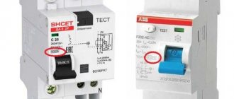
If the circuit breakers do not work
In this case, all electrical equipment and devices that are powered from this line are checked.
For example, if the lighting in a room stops working or 2 sockets on the wall do not work at the same time, then check the following nodes one by one:
- Turn off the power supply to the house network completely.
- Before checking the resistance, check whether the multimeter is working. This is done by short-circuiting the probes. The display should show “0”. If the readings are slightly different, for example, 0.1, this will indicate that the device has an error.
- Check the serviceability of the light bulb by unscrewing it from the socket. One probe touches the cartridge, and the other touches the end part. A buzzer and meter readings other than “0” and “1” indicate that the device is working.
- Check the wall switch by removing the panel, removing the screws, and removing it from the box. If there are no visible violations, then check the switch with a tester, installing probes on its contacts. The absence of a buzzer indicates that the switch is faulty and needs to be replaced. As a rule, after this the light appears in the room.
Determine the telephone line voltage yourself
Perhaps someday you will decide to install a landline telephone in your home. It is likely that you already have it, but for some unknown reason it has stopped working or is performing its tasks very poorly. In the first case (to select a suitable device) and the last (to carry out repairs correctly), it is necessary to measure the voltage in the telephone line. This can be done using a special device called a voltmeter. It is connected in parallel and indicates the voltage in the form of numbers or using an arrow. Please note that this device is capable of displaying the voltage value of direct current (indicated by the “-“ sign) and alternating current (indicated by the “ sign
"). You will need to find out the value of the DC voltage.
Capacitive antennas
There are also test kits that use a capacitive antenna as a receiver. It detects the magnetic component of the field created by current flowing through the wires. To obtain a strong magnetic field, the pair must be short-circuited at the remote end. The antenna allows you not only to identify a cable in a cable well or cross-connection, but also to trace it in the wall and even in the ground. A representative of this type of device is the Greenlee CTS 132J, which is essentially an intermediate link between test kits and locators.
Finding out meaning in unusual ways
If you do not have a voltmeter (which is quite possible, since this is not an essential item), then especially for this case, people experienced in this matter have come up with other methods for checking the voltage in the telephone line. The method is quite funny (at least it seems so at first glance), but very practical, easy and convenient. To implement it you will need a well-known vegetable - potatoes. Yes, yes, exactly potatoes.
The root vegetable needs to be cut in half, then insert (preferably into the core of the vegetable) the two ends of the stripped wire to a depth of one to two centimeters. The distance between two bare conductors should be very small. The main thing is that they do not touch, otherwise the network will short out. And the following changes should occur with potatoes. Around the conductor, which is connected to the positive field, the flesh of the vegetable will turn a little green, and foam will form near the negative one. In addition, the wire itself with the minus sign will become dark. This can be seen when you remove it from the vegetable.
Connecting a new phone
As mentioned above, the voltage in the telephone line is usually checked when a new device should be installed or an existing one should be repaired. Let's talk about connection first. But before starting this process, you need to consider the main types of telephone sockets. The first and most common type is RTShK-4. The connection is established in this way: the contacts of the socket (the line wires are connected to them) must coincide with the contacts of the plug (the telephone wires are connected to them).
The 623K RJ-116P4C socket is a more modern option, but also outdated. It is used not only to establish telephone communications, but also to provide Internet access. The two line conductors should generally be connected to the green and red wires.
You can connect your phone without a socket, using an RJ-11 plug. To do this, you need to take a telephone line wire, strip its two contacts and insert them into the RJ-11 connector. The wire is clamped using special pliers (crimpers) or manually (for example, by tapping the lamellas with the end of a flat screwdriver to the required depth).
Telephone or telephone line repair
Let's consider the second case, when voltage measurement is used on a telephone line. We said that repairs apply to this situation. A situation may occur in which the phone stops working for some reason. Then you should call a specialist: he will examine the device, find the cause of the malfunction, and quickly and efficiently fix everything. You can do the repair yourself. This is where methods for measuring telephone network voltage help. With their help, it is easy to determine what exactly has gone wrong. Perhaps the phone itself is broken. In this case the voltage will be fine. If it is missing, then most likely there is a breakdown on the communication line. Then you need to check the wire that goes to the outlet or the phone itself for damage. If a malfunction is detected, the wire should be replaced completely or directly at the point of failure.
How to test wires with a multimeter
If there is a power failure in a house or apartment, you will need to quickly check the in-house wiring. This will not be difficult when the home technician has a multimeter and knows the basic safety rules for working with voltage.
Testing the wires with a multimeter is performed to determine their suitability, the absence of internal breaks, short circuits in the electrical circuit and determine the resistance of the circuit. The method is the most effective, proven and accurate. The most inexpensive digital model can easily cope with this task. Before testing the wires with a multimeter, a home mechanic must learn how to operate the measuring device and turn off the current on the network being tested.
Why else do you need to know the voltage of the telephone line?
Agree that you live in an apartment or house, stuffed with modern means, devices and other gadgets. All of them are somehow connected to wires, since they cannot work without electricity.
It’s probably still useful to know what voltage a particular conductor has, since we use these devices almost every day. Therefore, if you know the voltage of the current passing in all the wires, then it is obvious that you can avoid danger. After all, a large electric discharge can give a person a lot of unpleasant sensations in the event of damage to its carrier and contact with it. But in other situations, knowledge in this area and firm confidence in the inability of the wire for various reasons to give an electric shock will help maintain calm and good mood.
In conclusion
Thus, knowing the voltage in the telephone communication line, you can easily and simply install a new device, repair an old one, and avoid contact with exposed conductors. It will also broaden your horizons and erudition, and you will have the opportunity to show off your unusual knowledge to your friends.
When carrying out electrical installation work, it may be necessary to test the cable, for example, when marking cores and wires, checking the insulation and integrity of the wiring, as well as searching for a broken electrical cable. Let's consider the ways in which testing can be carried out, as well as the equipment necessary for this purpose.
Methods
Testing methods depend on the purpose for which it is performed. To check the integrity of the cable for a break or electrical connection between its wires (short circuit), the continuity test can be done with a tester based on a battery and a light bulb, or you can use a multimeter for this purpose. The latter is preferable.
Despite the fact that the price of a multimeter is higher than a primitive device, we recommend buying it; this device will always be useful in the household.
The simplest device for testing an electrical cable
To check the cable, the multimeter must be turned on in the appropriate mode (diode or buzzer image).
Multimeter set to dialing mode
The testing methodology is as follows:
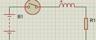
When checking a wire for a break, the tester is connected to its ends as shown in the figure. If the cable is intact, the light will glow (when testing with a multimeter, a characteristic sound signal will be heard).
Checking for a break
Explanations for the picture:
- A – electrical cable;
- B – cable cores;
- C – power source (battery);
- D – light bulb.
If the cable has already been laid, then on one side it is necessary to connect the wires together and ring the wires at the other end;
Second option for checking the power cable
when checking the presence of an electrical connection between the cable cores, the tester probes are connected to different wires. Unlike the previous example, there is no need to twist the wires on the other side. If there is no short circuit between the wires, the light will not light (when testing with a multimeter, no beep will sound).
If the circuit breakers have tripped
This option indicates that there has been a serious failure in the electrical networks of the house, perhaps even a short circuit. Most likely, the wiring has failed, which can be checked by continuity.
To do this, the owner must sequentially complete the following steps:
- Use a screwdriver to disconnect the wire. Usually, it is located below and taken to the side. The “0” wire of this group is usually located at the 0 terminal under the circuit breaker.
- Before finding a fault, remove the light bulb from the socket and then check the lighting line with a multimeter, connecting the 1st probe to “0” and the 2nd to the disconnected wire. When a sound signal appears, the wire is shorted.
- At the top of the room they find and open the panel, disconnect the wires.
- Each pair is checked for the presence of a short circuit.
- After identifying the defective area with a short circuit, it is again tested with a circuit meter on the input panel. If there is a sound from the tweeter, then repairs must be made on the wire from the switchboard to the box. If not, then continue to examine other wires using a similar method.
Testing multi-core cables for the purpose of marking them
When marking multi-core cables, you can use the methods described above, but there are ways to significantly simplify this process.
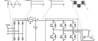
Method 1 : use of special transformers that have several secondary winding taps. The connection diagram for such a device is shown in the figure.
Using a transformer for marking
As can be seen from the figure, the primary winding of such a transformer is connected to the power supply network, one end of the secondary winding is connected to the protective shield of the cable, and the remaining terminals are connected to its conductors. To mark the wires, it is necessary to measure the voltage between the screen and each wire.
Method 2 : Use a block of resistors with different values connected to the cable wires on one side, as shown in the figure.
Resistors connected to cable terminals
To identify the cable, it is enough to measure the resistance between it and the screen. If you want to make such a device with your own hands, then you should select resistors in increments of at least 1 kOhm to reduce the influence of wire resistance. Also, do not forget that the value of the resistors has a certain error, so first measure them with an ohmmeter.
When checking a multi-core telephone cable, installers often use a dialing headset, for example TMG 1. Actually, these are two telephone handsets, one of which is connected to a 4.5 V battery. Such a simple device allows you not only to check the cable, but also to coordinate your actions during installation and testing.
Calling with a telephone handset
Continuity of wiring between junction boxes
It is difficult to understand the connections in the distribution box. Again, here we use the method of ringing wires with a multimeter. This requires an additional conductor, the length of which exceeds the distance between the boxes.
- First, the electricity in the apartment is turned off using an input circuit breaker.
- One end of the additional conductor is connected through “crocodiles” to one of the terminals in the box, and the other to one probe of the multimeter. At the same time, loads are switched off everywhere.
- Using another probe, find the corresponding terminal in another box based on the characteristic squeak of the device. The tested wire is marked and the others are wired in the same way. The broken conductor is found by the method of exclusion, when all other conductors have been checked.
Insulation check
To test insulation with a megohmmeter or multimeter, the principle of continuity is the same as when searching for an electrical connection between the cable cores.
The testing algorithm is as follows:
- set the maximum range on the device - 2000 kOhm;
- connect the probes to the wires and see what the device display shows. Considering that the wires have a certain capacitance until it is charged, the readings may vary. After a few seconds, the device display can display the following values:
- one, this indicates that the insulation between the wires is normal;
- zero – there is a short circuit between the cores;
- some average readings, this can be caused either by a “leak” in the insulation or by electromagnetic interference. To determine the cause, switch the device to the maximum range of 200 kOhm. If the insulation is faulty, the display will display stable readings; if they change, then we can confidently talk about electromagnetic interference.
Attention! Before checking the insulation of the electrical wiring, it must be de-energized. The second important point is that when taking measurements, do not touch the probes with your hands, this can introduce errors.
Video: Wire continuity check - integrity check.
Safety requirements
When performing any inspections of live electrical networks, safety requirements must be followed. You cannot work without protective insulated shoes, and it is also better to wear rubber gloves. When checking the integrity and insulation resistance of electrical circuits, it is necessary to de-energize the network by turning off the circuit breakers, so all checks should be carried out during daylight hours, since with emergency lighting and the light of lanterns you can only work in case of an emergency.
Testing the required cable pair at the cross-connect, in the coupling or at the remote end of the cable is an integral task for any engineer involved in the installation and maintenance of copper cable lines.
Finding the break point
After a break in the electrical wiring has been discovered, it is necessary to localize the place where it happened. For dialing in this case, you can use a tone generator, for example, the Cable Tracker MS6812R or TGP 42. Such devices allow you to determine the location of the break with centimeter accuracy, as well as determine the route of hidden wiring; in addition, the devices have other useful functions.
Model MS6812R
Devices of this type include an audio signal generator and a sensor attached to an earphone or speaker. When the sensor approaches the place where the UTP cable pairs or electrical wiring wires are broken, the tone of the sound signal changes. When a tone test is performed, the wiring must be de-energized before connecting the sound generator, otherwise the device will be damaged.
Note that with the help of this device you can test both power and low-current cables, for example, check the integrity of twisted pair cables, radio wiring or communication lines. Unfortunately, such devices will not allow you to determine the correct connection; special equipment is used for this purpose - cable testers.
conclusions
Today, it is more convenient and faster to test a cable not using a handset or headset, but using a test kit, which includes a tone generator and a receiver probe, usually shaped like a handset with a speaker.
The sound from such a probe is perfectly audible, and you don’t even need to touch the cables. It is enough just to move such a probe past the cable pairs to quickly find the one you are looking for. The speed of work increases many times over. Such a test set will allow one person to carry out dialing, as well as trace the desired wire behind a false wall, behind a suspended ceiling, and even in the ground. See also:
Main characteristics of tone generators for cable testing
Cable Stockings: Selection Guide
Shortening factor or how to accurately measure the distance to a fault in a cable?
Cable testers
This class of devices allows you to check both the integrity of the cable and the correctness of its connection, which is very important for Internet provider networks. These can be simple devices that check crossover or complex devices on a PIC controller that have an ADC and a built-in multiplexer.
Multipurpose cable tester Pro'sKit MT-7051N on a microcontroller
Naturally, the cost of such devices does not encourage their household use.