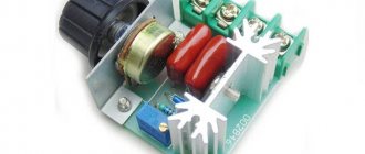
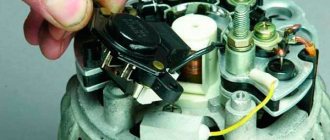
The regulator board removed from the vacuum cleaner was tested on a 220 V / 95 W light bulb connected to it. To do this, you first need to attach the board to at least some kind of base - a dielectric, and put a handle made of material that does not conduct electric current on the potentiometer (variable resistance that directly produces a change in the amount of power), because “220 V around” can appear on the regulator board. Carefully moving the handle of the slider resistor, I found out that the light bulb glows at full power, but does not stop glowing. The resistor, even when “turned out” to failure, does not reduce the power to “0”.
The principle of operation of the regulator on a triac
Let us recall that a triac is usually called a modification of a thyristor that plays the role of a semiconductor switch with a nonlinear characteristic. Its main difference from the basic device is two-way conductivity when switching to the “open” operating mode, when current is supplied to the control electrode. Thanks to this property, triacs do not depend on voltage polarity, which allows them to be used effectively in circuits with alternating voltage.
In addition to the acquired feature, these devices have an important property of the base element - the ability to maintain conductivity when the control electrode is disconnected. In this case, the “closing” of the semiconductor switch occurs when there is no potential difference between the main terminals of the device. That is, when the alternating voltage crosses the zero point.
An additional bonus from this transition to the “closed” state is the reduction in the amount of interference during this phase of operation. Please note that a regulator that does not create interference can be created under the control of transistors.
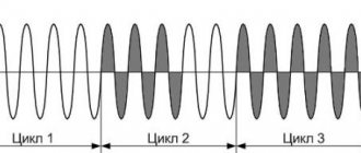
Thanks to the properties listed above, it is possible to control the load power through phase control. That is, the triac opens every half-cycle and closes when crossing zero. The delay time for turning on the “open” mode, as it were, cuts off part of the half-cycle, as a result, the shape of the output signal will be sawtooth.
Signal shape at the output of the power regulator: A – 100%, B – 50%, C – 25%
In this case, the signal amplitude will remain the same, which is why it is incorrect to call such devices voltage regulators.
Types of regulators
Nowadays on the market you can see a huge number of different regulators both for the whole house and for low-power individual household appliances. There are transistor voltage regulators, thyristor, mechanical (voltage adjustment is carried out using a mechanical slider with a graphite rod at the end). But the most common is the triac voltage regulator. The basis of this device are triacs, which allow you to react sharply to voltage surges and smooth them out.
A triac is an element that contains five pn junctions. This radio element has the ability to pass current both in the forward and reverse directions.
These components can be observed in various household appliances, from hair dryers and table lamps to soldering irons, where smooth adjustment is necessary.
Regulator circuit options
Let's give a few examples of circuits that allow you to control load power using a triac, starting with the simplest.
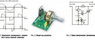
Figure 2. Diagram of a simple triac power regulator powered by 220 V
Designations:
- Resistors: R1- 470 kOhm, R2 – 10 kOhm,
- Capacitor C1 – 0.1 µF x 400 V.
- Diodes: D1 – 1N4007, D2 – any indicator LED 2.10-2.40 V 20 mA.
- Dinistor DN1 – DB3.
- Triac DN2 - KU208G, you can install a more powerful analog BTA16 600.
With the help of dinistor DN1, the circuit D1-C1-DN1 is closed, which moves DN2 to the “open” position, in which it remains until the zero point (completion of the half-cycle). The moment of opening is determined by the time of accumulation on the capacitor of the threshold charge required to switch DN1 and DN2. The rate of charge C1 is controlled by the chain R1-R2, the total resistance of which determines the moment of “opening” of the triac. Accordingly, the load power is controlled through a variable resistor R1.
Despite the simplicity of the circuit, it is quite effective and can be used as a dimmer for filament lighting or a soldering iron power regulator.
Unfortunately, the above circuit does not have feedback, therefore, it is not suitable as a stabilized speed controller of a commutator electric motor.
Triac-based circuits
If for some reason it is not possible to purchase a ready-made power regulator, then it is quite possible to make it yourself. It is necessary to decide in advance for which electrical appliance it will be made.
Often, when purchasing a regular soldering iron, its temperature is so high that the tracks on printed circuit boards can peel off, as well as damage to radio components. Here is one of the power regulator circuits using a triac.
This circuit is quite easy to assemble and does not require many parts. Such a regulator can be used to regulate not only the temperature of the soldering iron, but also conventional incandescent and LED lamps. This circuit can be used to connect various drills, grinders, vacuum cleaners, and sanders, which initially came without smooth speed control.
You can assemble such a 220V voltage regulator with your own hands from the following parts:
- R1 is a 20 kOhm resistor with a power of 0.25 W.
- R2 is a variable resistor 400-500 kOhm.
- R3 - 3 kOhm, 0.25 W.
- R4—300 Ohm, 0.5 W.
- C1 C2 - non-polar capacitors 0.05 microfarads.
- C3 - 0.1 microfarads, 400 V.
- DB3 - dinistor.
- BT139−600 - the triac must be selected depending on the load that will be connected. A device assembled according to this circuit can regulate a current of 18A.
- It is advisable to use a radiator for the triac, since the element gets quite hot.
The circuit has been tested and works quite stably under different types of load..
There is another scheme for a universal power regulator.
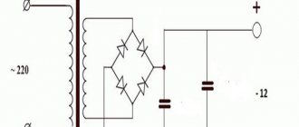
An alternating voltage of 220 V is supplied to the input of the circuit, and 220 V DC is supplied to the output. This scheme already has more parts in its arsenal, and accordingly the complexity of the assembly increases. It is possible to connect any consumer (DC) to the output of the circuit. In most houses and apartments, people try to install energy-saving lamps. Not every regulator can cope with smooth adjustment of such a lamp; for example, it is not advisable to use a thyristor regulator. This circuit allows you to easily connect these lamps and make them into a kind of night lights.
The peculiarity of the scheme is that when the lamps are turned on to minimum, all household appliances must be disconnected from the network. After this, the compensator in the meter will work, and the disk will slowly stop, and the light will continue to burn. This is an opportunity to assemble a triac power regulator with your own hands. The values of the parts needed for assembly can be seen in the diagram.
Another entertaining circuit that allows you to connect a load of up to 5A and a power of up to 1000W.
The regulator is assembled on the basis of the BT06−600 triac. The operating principle of this circuit is to open the triac junction. The more the element is open, the more power is supplied to the load. There is also an LED in the circuit that will let you know whether the device is working or not. List of parts that will be needed to assemble the device:
- R1 is a 3.9 kOhm resistor and R2 is a 500 kOhm resistor, a kind of voltage divider that serves to charge capacitor C1.
- capacitor C1- 0.22 µF.
- dinistor D1 - 1N4148.
- LED D2 serves to indicate the operation of the device.
- dinistors D3 - DB4 U1 - BT06−600.
- terminals for connecting the load P1, P2.
- resistor R3 - 22 kOhm and power 2 W
- capacitor C2 - 0.22 µF is designed for a voltage of at least 400 V.
Triacs and thyristors are successfully used as starters. Sometimes it is necessary to start very powerful heating elements, to control the switching on of powerful welding equipment, where the current strength reaches 300-400 A. Mechanical switching on and off using contactors is inferior to a triac starter due to the rapid wear of the contactors; moreover, when switching on mechanically, an arc occurs, which also has a detrimental effect on contactors. Therefore, it would be advisable to use triacs for these purposes. Here is one of the schemes.
All ratings and parts list are shown in Fig. 4. The advantage of this circuit is complete galvanic isolation from the network, which will ensure safety in the event of damage.
Feedback regulator circuit
Feedback is necessary to stabilize the speed of the electric motor, which can change under the influence of load. You can do this in two ways:
- Install a tachometer that measures the speed. This option allows for precise adjustment, but this increases the cost of implementing the solution.
- Monitor voltage changes on the electric motor and, depending on this, increase or decrease the “open” mode of the semiconductor switch.
The latter option is much easier to implement, but requires slight adjustment to the power of the electric machine used. Below is a diagram of such a device.
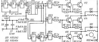
Power regulator with feedback
Designations:
- Resistors: R1 – 18 kOhm (2 W); R2 - 330 kOhm; R3 – 180 Ohm; R4 and R5 – 3.3 kOhm; R6 – must be selected as described below; R7 – 7.5 kOhm; R8 – 220 kOhm; R9 – 47 kOhm; R10 - 100 kOhm; R11 – 180 kOhm; R12 – 100 kOhm; R13 – 22 kOhm.
- Capacitors: C1 - 22 µF x 50 V; C2 - 15 nF; C3 – 4.7 µF x 50 V; C4 – 150 nF; C5 - 100 nF; C6 – 1 µF x 50 V..
- Diodes D1 – 1N4007; D2 – any 20 mA indicator LED.
- Triac T1 – BTA24-800.
- Microcircuit – U2010B.
This circuit ensures a smooth start of the electrical installation and protects it from overload. Three operating modes are allowed (set by switch S1):
- A – When overload occurs, LED D2 turns on, indicating overload, after which the engine reduces speed to minimum. To exit the mode, you must turn off and turn on the device.
- B - If there is an overload, LED D2 turns on, the motor is switched to work at minimum speed. To exit the mode, it is necessary to remove the load from the electric motor.
- C – Overload indication mode.
Setting up the circuit comes down to selecting resistance R6; it is calculated depending on the power of the electric motor using the following formula: . For example, if we need to control a 1500 W motor, then the calculation will be as follows: 0.25 / (1500 / 240) = 0.04 Ohm.
To make this resistance, it is best to use nichrome wire with a diameter of 0.80 or 1.0 mm. Below is a table that allows you to select the resistance R6 and R11, depending on the engine power.
Table for selecting resistance ratings depending on engine power
The above device can be used as a speed controller for motors of power tools, vacuum cleaners and other household equipment.
Why adjust the rotation speed of the grinder disc at all?
- When cutting metal of different thicknesses, the quality of work greatly depends on the speed of rotation of the disk. If you are cutting hard and thick material, you must maintain maximum rotation speed. When processing thin sheet metal or soft metal (for example, aluminum), high speeds will lead to melting of the edge or rapid blurring of the working surface of the disk;
- Cutting and sawing stone and tile at high speed can be dangerous. In addition, the disk, which rotates at high speeds, knocks small pieces out of the material, making the cutting surface chipped. Moreover, different speeds are selected for different types of stone. Some minerals are processed at high speeds;
- Grinding and polishing work is in principle impossible without adjusting the rotation speed. By setting the speed incorrectly, you can damage the surface, especially if it is a paint coating on a car or a material with a low melting point;
- The use of discs of different diameters automatically implies the presence of a regulator. Changing a disk Ø115 mm to Ø230 mm, the rotation speed must be reduced by almost half. And holding a grinder with a 230 mm disc rotating at a speed of 10,000 rpm is almost impossible to hold in your hands;
- Polishing of stone and concrete surfaces, depending on the type of crowns used, is carried out at different speeds. Moreover, when the rotation speed decreases, the torque should not decrease;
- When using diamond discs, it is necessary to reduce the number of revolutions, since their surface quickly fails due to overheating. Of course, if your grinder works only as a cutter for pipes, angles and profiles, you won’t need a speed controller. And with the universal and versatile use of angle grinders, it is vital.
Regulator for inductive load
Those who try to control an inductive load (for example, a welding machine transformer) using the above circuits will be disappointed. The devices will not work, and the triacs may fail. This is due to a phase shift, which is why during a short pulse the semiconductor switch does not have time to switch to the “open” mode.
There are two options to solve the problem:
- Supplying a series of similar pulses to the control electrode.
- Apply a constant signal to the control electrode until it passes through zero.
The first option is the most optimal. Here is a diagram where this solution is used.
Power regulator circuit for inductive load
As can be seen from the following figure, which shows oscillograms of the main signals of the power regulator, a packet of pulses is used to open the triac.
Oscillograms of the input (A), control (B) and output signal (C) of the power regulator
This device makes it possible to use regulators on semiconductor switches to control an induction load.
Principle of operation
The principle of operation of a triac is quite simple. This is a kind of electronic key that either closes or opens doors at a given frequency. When the PN junction of the triac is opened, it passes a small part of the half-wave and the consumer receives only part of the rated power. That is, the more the PN junction opens, the more power the consumer receives.
The advantages of this element include:
- Triacs are quite durable, since they have no mechanical contacts.
- Due to the lack of a mechanical component, there is no sparking.
- At moments of zero mains current, the triac can carry out switching, which thereby reduces the amount of interference and ensures high accuracy of the circuit.
In connection with the above advantages, triacs and regulators based on them are used quite often.
A simple power regulator on a triac with your own hands
At the end of the article, we will give an example of a simple power regulator. In principle, you can assemble any of the above circuits (the most simplified version was shown in Figure 2). For this device it is not even necessary to make a printed circuit board; the device can be assembled by surface mounting. An example of such an implementation is shown in the figure below.
Homemade power regulator
This regulator can be used as a dimmer, and can also be used to control powerful electric heating devices. We recommend choosing a circuit in which a semiconductor switch with characteristics corresponding to the load current is used for control.
Common models
There are models of ready-made power regulators. One of the representatives is the RM-2 model. Quite a simple model and inexpensive model. The price ranges from 1300 to 1500 rubles. The device is designed for voltage from 30 to 400 V. It can also be used both at home and in production. As a rule, the device is used to regulate the temperature of various electric heating equipment.
The next modification will be the PM 2 16A model. This device is mainly used in large industrial enterprises, but it can also be used at home. The task of the RM 2 16 A is to change the lighting level and control the rotation of motors of various types.
The input voltage should not exceed 400 V, and the load should not exceed 16A. The price of this device can cost 2300 rubles.
The RNE-1 model has found its application in domestic conditions: for adjusting the heating of a soldering iron, changing the brightness of lamps (use as a dimmer), and you can also successfully connect heaters and regulate the temperature. The design of the device includes short circuit protection, which is presented in the form of a fuse. If there is excessive overheating, thermal protection is triggered and the regulator stops the energy supply to the device. After cooling, the device can be turned on again and continued to be used. The low price is quite a significant advantage and amounts to 1200 rubles.
If the buyer has knowledge in the field of radio electronics, then you can assemble the current regulator with your own hands, and the NF model will be the best choice. The kit includes a printed circuit board made of foil fiberglass, various electronic components. The price of this model ranges from 900 to 1100 rubles.
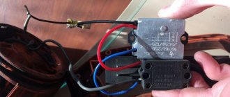
Can the vacuum cleaner's power regulator be used to charge batteries?
Disassembled the vacuum cleaner for cleaning. It has such a power regulator. Is it possible to remove it so that the motor can work at full power, because... the regulator at a lower speed; I don’t use a vacuum cleaner; it’s weak. How to connect the motor directly? And is it possible to use this regulator in a circuit for charging a car battery?
Comments 72
I have a good circuit, as simple as 3 kopecks. Trans, diode bridge, thyristor, transistor KT117, and wiring. Well, and an ammeter. If anyone needs it, I can send you the circuit.
What is it good for?, what does it give? Does it regulate voltage and current? Should the payment be sent?((
It regulates the current, the voltage at the output of the transformer should be 17 volts, naturally the diodes have a current within 8A, the thyristor is the most important component (if it is short it crashes, there is no protection circuit).
wladgorinov
I have a good circuit, as simple as 3 kopecks. Trans, diode bridge, thyristor, transistor KT117, and wiring. Well, and an ammeter. If anyone needs it, I can send you the circuit.
please send me a PM
Why bother suffering, the half-bridge circuit is 4.5 Amperes. It will take longer to charge, but it will be enough for recharging.
You can leave the vacuum cleaner without a regulator, it will thresh at maximum.
Can. if this regulator is connected from the mains side to a “brainless” charger on an iron transformer
Have you tried it yourself?
But you need to understand: it will allow you to regulate the current, but this will not make the charger automatic. Those. You still have to monitor the voltage/current
I also lick it when I charge it, because... no smart charging(
short-circuit
Can. if this regulator is connected from the mains side to a “brainless” charger on an iron transformer
This is the only one I have) An ampere-voltmeter arrived from China, I want to plug it in. Those. your answer is yes?! Will it regulate the current?
I made a basic charge for the battery by taking an 18-volt laptop charger and connecting it in series with a regular 12-volt lamp. 8 hours and the battery is charged))))
Yes, I did that, it works!)
buy a standard charger, because cutting it out leads to getting caught. I often saw discarded old TVs in landfills; you can also assemble a charger and a welding machine from them. There are diagrams on the Internet
I read the advice and laughed. Some comments are so ridiculous
And what’s interesting is that crazy ideas are getting a ton of comments
Google the offices in your city that sell spare parts for household appliances, and buy a normal motor for a vacuum cleaner there. It’s better to leave the idea with a dimmer for charging the battery