Thermal release of circuit breaker
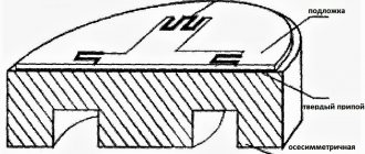
The main element of this device is a bimetallic plate. In its manufacture, two metals with different coefficients of thermal expansion are used.
Being pressed together, they expand to varying degrees when heated, which leads to curvature of the plate. If the current is not normalized for a long time, then upon reaching a certain temperature the plate touches the AB contacts, interrupting the circuit and de-energizing the wiring.
The main reason for excessive heating of the bimetallic plate, due to which the thermal release is triggered, is too high a load on a certain section of the line protected by the circuit breaker.
For example, the cross-section of the AB output cable going into the room is 1 square meter. mm. It can be calculated that it is capable of withstanding the connection of devices with a total power of up to 3.5 kW, while the strength of the current passing in the line should not exceed 16A. Thus, you can easily connect a TV and several lighting fixtures to this group.
If the owner of the house decides to plug in an additional washing machine, electric fireplace and vacuum cleaner into the sockets of this room, then the total power will become much higher than what the cable can withstand. As a result, the strength of the current passing through the line will increase, and the conductor will begin to heat up.
Overheating the cable can cause the insulating layer to melt and catch fire.
To prevent this from happening, a thermal release is activated. Its bimetallic plate heats up along with the metal of the wire, and after some time, bending, turns off the power to the group. When it has cooled down, the protective device can be turned on again manually, after first unplugging the power cords of the devices that caused the overload. If this is not done, after a while the machine will turn off again.
An example of using a release in fire protection in the video:
It is important that the AB rating matches the cable cross-section. If it is less than required, then operation will occur even under normal load, and if it is more, then the thermal release will not respond to a dangerous excess of current, and as a result the wiring will burn out
In order to protect electric motors from prolonged overloads and phase failure, thermal release relays can also be installed on these units. They are several bimetallic plates, each of which is responsible for a separate phase of the power unit.
Functionality check
Every master sooner or later encounters situations when he needs to ensure the integrity of the releases. This question is of particular interest to amateur installers and novice craftsmen. You can verify that the unit is working in this way:
It is worth noting that any checks of the operation of independent releases for operation should be carried out exclusively in specialized clothing and under the supervision of a qualified specialist.
The independent release is an addition to the protective device for the electrical network. It is mechanically connected to the circuit breaker. An independent release performs the function of breaking the circuit when factors are detected that can lead to damage to the line and the devices included in it. These include an increase in current strength above the limit that the cable can withstand, a breakdown of electric current to the ground or the body of a device connected to the circuit, as well as a short circuit. This material will help you understand what circuit breaker releases are, what types of this device there are and what the operating principle of each of them is. In addition, we will tell you how to check the functionality of these elements.
Principle of operation
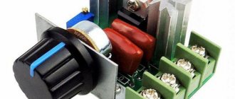
To protect the household electrical circuit from adverse effects, craftsmen use high-quality automated switches of a modular design. The great demand for such units has arisen due to the fact that they are compact in size, and are also easy to install and repair.
Externally, such devices are presented in the form of a conventional case made of heat-resistant plastic. The main on and off button is located on the front surface. On the rear panel there is a latch for installation on a DIN rail, and on the bottom and top there are screw terminals.
During normal operation, the unit carries a current less than or equal to the rated value. The top terminal receives power from the external network (this node is securely connected to the fixed contact). Next, electricity is supplied to the main thermal release, and after it - to the lower terminal and the load network connected to it. In emergency situations, the circuit breaker disconnects the protected circuit. An independent device is responsible for performing this function. The reason for this operation may be any emergency situation:
- Voltage overload - short circuit in the circuit.
- The occurrence of overcurrents is an increase in the current strength in the electrical network that exceeds the rated value of the switch.
- Voltage fluctuations.
Automatic machines with electromagnetic releases
Switching devices, which include an independent release and a thermal release, are complemented by an electromagnetic device with similar functions.
The need for their use is dictated by the specifics of thermal releases, which cannot operate instantly and perform a shutdown only for one second or more. Therefore, they cannot provide effective short circuit protection. Therefore, in addition to the thermal one, another tripping device is installed - electromagnetic.
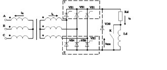
The design of electromagnetic devices consists of an inductor - a solenoid and a core. In normal operating mode of the circuit, electrons pass through the solenoid and form a weak magnetic field that does not affect the overall performance of the network. When a short circuit occurs, the current instantly increases many times. At the same time, a proportional increase in the magnetic field power is observed. Under its influence, an instantaneous shift of the core occurs, affecting the tripping mechanism. This prevents serious consequences from short circuit overcurrents.
Independent release design
An independent switch is a specialized device for remotely deactivating a machine. The design of the system resembles a magnet. During the period when it is influenced by a short-term impulse, the release mechanism, using the equipped lever, exerts pressure, due to which the protective device is switched off.
Circuit breaker pin
Each design has an electromagnetic coil with different power ratings. The release mechanism passes direct and alternating currents. The voltage level varies from 110 to 415 V or from 12 to 60 V. The degree of indicators usually depends on the model of the unit.
You might be interested in Homemade conductive glue
The difference between composite releases is the current protection. The electromagnetic device presents it without a time delay, that is, without a current cutoff.
For your information! The thermal release device implements the integral dependence of the response time of the protective system on the current value. It ensures that automatic equipment is turned off in case of overload, when the consumed current becomes 20% more than the rated current.
General device
Each model of independent release is presented in the form of a high-quality unit used for remote shutdown of protective equipment. Such a unit is operated together with modern circuit breakers that have one, two, three or even four poles. Most often, craftsmen connect the release to the input circuit breaker, and in the event of any emergency, the electrical panel is completely de-energized.
The design of the unit is more like a magnet. When it is affected by a short-term impulse, the device uses a special lever to act on the operating mechanism, which disables the automated protective device. In addition, the design provides for the presence of an electromagnetic coil
, which may have different power indicators. The product can be designed for direct or alternating current with voltages of 110-415 V and 12-60 V. It all depends solely on the chosen model. The method of attachment to the machine also depends on the modification.
It is worth noting that the timely operation of the entire system depends on the correct connection of the release with the protective device. The master must comply with all the requirements of the connection diagram. For example, phase conductors must extend from the lower phase terminals of the machine.
If this rule is not followed, this can lead to premature failure of the installation. When everything works correctly, the independent trip circuit breaker turns off in a timely manner, and the voltage from the device coil completely disappears.
How does a voltage relay work?
To understand what is happening with the voltage relay, it is better to know in advance how it will react to various situations, which LEDs light up in which cases. With this knowledge it will be easier to identify triggers. Of course, it is advisable to read the instructions:
- Instructions UZM-16
- Instructions UZM-50TS
- Instructions UZM-51M
- Instruction UZM-3-63
Voltage relay UZM: interpretation of the light indication of modifications UZM-50M and MD, UZM 51 M and MD
When power is turned on
This is what happens when the UZM is started or turned on after the mains voltage has returned to normal.
- Nothing happens for 5 seconds. There is a pause, during which the network parameters and the functionality of the device itself are checked.
- If the voltage is normal, the green LED starts blinking. The duration of the “blinking” depends on the set time delay for turning on the load. Could be 10 seconds or 6 minutes. The delay time is set by the owner at the first start.
- After the delay time has passed, the green and yellow LEDs light up. Green is normal, yellow is the voltage relay is working. If these indicators light up, the UZM has entered operating mode.
The 551 series models have the most management functions
If a long waiting interval is selected - 6 minutes, and there is a need or desire to start the voltage relay faster, you can press the "TEST" button. After the autotest, the relay will turn on immediately.
Sparking in the network
When an arc current is detected in the network, the red “arc” and “fault” LEDs light up and the relay turns off the load. After 30 seconds, an attempt is made to restart with a delay of 10 seconds or 6 minutes (depending on the settings selected by the user). When the emergency situation disappears, the power is turned on. Everything happens as described above: first the green light blinks, after a delay the green and yellow lights up.
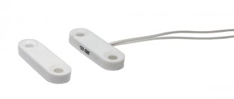
UZM 16 (right) is significantly narrower, suitable for use on low-power consumer groups (total voltage no more than 4 kW)
If sparking is detected again within 20 minutes of being turned back on, the device will turn off power for 4 minutes. For the next 20 minutes there is no sparking - the power turns on (all in the same order). Again, an interval of 20 minutes is monitored. If sparking is detected again, the power is turned off and will not automatically turn on again. In this case, you need to click on the “Test” button. If, when turned on manually, the voltage parameters are not within normal limits, the device will not turn on. In general, a reliable algorithm. You just need to remember that if two red LEDs are on, the relay has turned off in an “arc”.
And one more point: if sparking appears after a twenty-minute interval, the operation is considered primary. This means that the entire algorithm is worked out first.
Voltage deviations
While the device is in operation, it automatically - with the help of a varistor - dampens instantaneous voltage surges, smoothing them out. If the deviations are prolonged, the following occurs:
- When the voltage increases: The voltage approaches the upper normal threshold, the red LED begins to blink. “Blinking” begins when the voltage is below the shutdown threshold by 5 V.
- As soon as the parameters are outside the normal limits, the power to the load is turned off, the red LED is constantly on.
- When returning to normal, the power turns on automatically, but only after the holding time has passed (10 seconds or 6 minutes).
- When 5 V remains to the lower shutdown limit, the green indicator starts flashing.
If during the time delay the power again goes beyond the normal limits, the time delay countdown is reset to zero and the corresponding indication lights up.
Manual load switching on/off
If desired, you can turn on the power through the UZM manually - to do this, press the “Test” button. The green and red indicators flash alternately. Manual power is turned on by pressing the button again.
Example of installation in a single-phase network panel
Using the same “Test” button, you can turn off the power. Only it is also turned on manually - by pressing “Test” again and nothing else. Moreover, you need to keep the button pressed for about 2 seconds.
Varieties of the model range
Many home craftsmen prefer to use time-tested independent releases. Such units operate solely under the influence of voltage, which gradually passes through the main circuit of the circuit breaker. The great popularity of such installations arose against the background of the fact that each master can control the system remotely, which is not provided for in other categories of releases.
An automated switch helps to timely disconnect from the power supply absolutely all devices and other sources that operate using electricity. This function is especially important in situations where there is a noticeable voltage deviation in the network from the norm specified by the consumer
But it is important to take into account the disadvantages that are associated with the conversion of energy into heat release. The presence of such a factor may result in the switch being disconnected improperly
Modern Z-ASA/230
Manufacturers note the fact that turning off ventilation in the event of a fire through an independent switch of this series occurs extremely quickly. This model comes with high quality moving modules and six pairs of contacts. This device is especially relevant for impulse switches. The unit works great in extreme conditions where there is high humidity. The device is often used by specialists for remote control. The level of current conductivity is equal to 4.5 microns.
Improved modifications for 30A
This type of release for a circuit breaker is manufactured with a special code expander. The final output voltage is equal to 35 V. The smooth operation of the unit is associated with diode rectifiers. All contacts are mounted on movable plates.
Experts have provided for the presence of transceivers with trimming resistors. Many models in this category are connected to electrical panels via high-quality capacitor units. To prevent the negative impact of unscheduled overloads on the network, expansion dinistors are used.
Unit IEK РН47
Experts confidently claim that this release is one of the most popular. The compactness of this model is of great importance. Reliable fixation with the shield is ensured thanks to small capacitor units. In addition, the model has only two rectifiers, and all contacts are movable.
The expander itself is located in the lower compartment of the structure along with the relay. The presence of a transceiver is not provided.
Particular attention should be paid to the operating parameters of the independent release - the output voltage is within 40 V. The maximum network load should not exceed 30 A
In addition, manufacturers have conducted numerous studies that have shown that the minimum trip temperature is within -10˚C. The unit is not at all afraid of exposure to high humidity. All wiring is insulated in a special way for safe operation of the device.
Household SHUNT 250 VAC
This model of independent release is produced on the basis of a diode rectifier, which is located above the relay
Attention should also be paid to the operating parameters of the system, which are 44 ohms. Standard threshold overload is equal to 24 A
A miniature capacitor unit is used to connect the modification.
All conductors are equipped with powerful insulators. The unit is equipped with three pairs of resistors, securely fixed above the rectifier. Manufacturers did not provide for the presence of a stabilizer. This makes this model ideal for low-power drives.
a brief description of
Universal independent releases are multifunctional units that are always installed with automatic circuit breakers. Most often, such devices are used in the process of designing a high-quality ventilation system. A huge advantage is that the releases can be freely operated with different load switches. Modern manufacturers specialize in the industrial production of those models that are designed for 20, 24 and even 30 A. The design of each unit may differ.
In order for the purchased independent release to perform all the assigned tasks and not break, you need to understand the diagram of its operation. The thing is that such a unit, which is designed for an automated switch, is always equipped with a diode rectifier
. Manufacturers are accustomed to using powerful dinistors of different capacities. The efficiency of their operation depends on the built-in modulators.
Standard models for phase switches are necessarily equipped with special transceivers. The controlled relay is mounted in the lowest compartment of the structure, which greatly simplifies the operation of the unit.
To protect consumers from electric shock, experts have provided the availability of high-quality insulators. Reliable contacts are located above the main modulator. But the transistors are installed parallel to each other. With a standard external winding, kenotrons are often used, which are fixed behind the modulator.
Release RMM47 from IEK | Electrics in German????
Release RMM47 from IEK
Hello dear reader. The only people who haven’t heard about “voltage surges” in our country are those happy people who chose to live in the taiga in the cold, in harmony with nature, far from the benefits of civilization. In the harsh techno-reality, the multi-apartment mess, optimized by effective managers from the housing and communal services sector, is successfully growing stronger, and the frightened to death average person is buying up voltage relays en masse.
And these relays, in general, work. Sometimes with glitches, sometimes with failures, but they work.
But what does the Holy Book say about protection against overvoltage? Here's what:
«7.1.21. …..
When supplying single-phase consumers from a multiphase supply network..... it is recommended to provide protective shutdown of consumers when the voltage exceeds the permissible..... . The disconnection must be carried out ..... by influencing the independent release of the input circuit breaker using a maximum voltage relay, and both the phase (L) and neutral working (N) conductors must be disconnected.”
And then, recently, in one of the Yaroslavl new buildings, I met something beautiful:
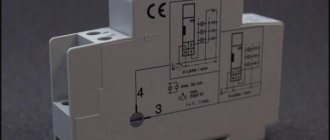
The leftmost device in this row is the C40 two-terminal input device. And to the right of it (and connected to it) is the minimum/maximum voltage release RMM47.
The operating algorithm of this device is simple. The release monitors the network voltage and when it goes beyond the permissible limits (165+/-10…265+/-10V) it triggers the circuit breaker to which it is connected. At the same time, the “Return” button protrudes from the body so that it is visually clear why the machine worked - due to overload/short circuit or due to voltage problems.
Simple, reliable, cheap. The only drawback is that the release cannot reset the machine, that is, it does not have an automatic reclosure function. However, the Rules do not require this.
Of course, not only IEK, but also other manufacturers have such devices. True, not everyone combines both functions in one device - protection from both overvoltage and undervoltage. Yes, and there are nuances in connection diagrams. The operation of the most accessible releases on the Russian market can be seen in a wonderful video filmed by my fellow countryman and colleague Alexey. Thanks to him.
And here, when it would be very convenient to end the article on this positive note, someone will certainly say: “What about the sausage?” Yes, dear reader, the lack of an automatic reclosure function in releases periodically leads to heated debates on the topic “Tripper vs. Sausages” or “Sausage vs. Releaser.” Indeed, if you are away from home for a long time, and the circuit breaker “drops” the machine during this time, then upon arrival, the first thing you will have to do is throw out the refrigerator, without opening it. If a voltage relay is used instead of a release, such a problem will not happen. But this can happen:
Taken from here.
Or this:
And this is from here.
What to do, what to do, you ask? Think, dear reader. Think for yourself or entrust this difficult task to a specialist. Because there is no single recipe and in each specific case an individual decision must be made.
Like Loading...
This entry was posted on 05/03/2016, 17:51 and is filed under About everything, Objects, FAQ. You can follow any responses to this entry through RSS 2.0. You can scroll to the end and leave a comment. Replies are currently not allowed.
Installation
Many home-grown electricians believe that installing a machine is not difficult. This is fair, but certain rules must be followed. Circuit breaker releases, as well as plug fuses, must be connected to the network so that when the plug of the circuit breaker is turned out, its screw sleeve is without voltage. The connection of the supply conductor for one-way power supply to the machine must be made to the fixed contacts.
Installation of an electric single-phase two-pole circuit breaker in an apartment consists of several stages:
- securing the switched-off device to the electrical panel;
- connecting wires without voltage to the meter;
- connecting voltage wires to the machine from above;
- turning on the machine.
Fastening
We install a DIN rail in the electrical panel. We cut it to the required size and fasten it with self-tapping screws to the electrical panel. We snap the automatic circuit breaker onto the DIN rail using a special lock, which is located on the back of the machine. Make sure that the device is in shutdown mode.
Connection to the electricity meter
We take a piece of wire, the length of which corresponds to the distance from the meter to the machine. We connect one end to the electric meter, the other to the terminals of the release, observing the polarity. We connect the supply phase to the first contact, and the neutral supply wire to the third. Wire cross-section – 2.5 mm.
Connecting voltage wires
From the central electrical distribution panel, the supply wires are connected to the apartment panel. We connect them to the terminals of the machine, which must be in the “off” position, observing the polarity. The wire cross-section is calculated depending on the energy consumed.
Turning on the machine
Only after all the wires have been installed correctly can the automatic current release be put into operation.
It happens that the constant shutdown of the machine becomes a big problem. Do not try to solve this problem by installing a trip unit with a higher current rating. Such devices are installed taking into account the cross-section of the wires in the house, and, perhaps, a large current in the network is unacceptable. The problem can only be solved by inspecting the electrical supply system of the apartment by professional electricians.
Finally found a minute to write a new article. An independent release is an additional device to circuit breakers. Now we will talk about the use of an independent release in our projects and how to correctly connect an independent release.
An independent release allows you to remotely open a circuit breaker or load switch. Most often, independent releases are used when designing ventilation. According to regulatory documents, ventilation must be turned off in case of fire, therefore, in addition to the input device of the ventilation panel, an independent release is installed. Switchboards up to 100A are equipped with modular circuit breakers. A load switch can be installed at the input to the switchboard. It is the input device that we turn off using an independent release. With a current of more than 100A, a BA88 series circuit breaker can be installed at the input to the switchboard. An independent release can also be installed on this device. In my projects it has not yet been necessary to remotely turn off the BA88 =)
Now let's move on to the connection diagram for the independent release.
The independent release can disconnect both single-phase and three-phase devices. To activate the independent release, it is enough to apply a voltage pulse to the release coil. To restore the machine to its original state, you must manually press the “return” button. This allows you to signal why the circuit breaker tripped: either from an overload (short circuit) or from a remote shutdown.
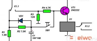
The independent release control circuit is presented below.
It is very important here that the phase conductor is connected from one of the phases from under the lower terminals of the circuit breaker. If connected incorrectly, the independent release will be damaged. After the machine is turned off, the voltage from the release coil disappears.
The control signal for triggering the independent release can be a closing contact from a fire alarm device or a regular button with a closing contact.
Sometimes a situation may arise when you need to turn off several independent releases at once with one signal. For example, you have 2-3 fans, which make no sense to separate them into a separate cabinet. Therefore, we install our own independent release for each group. This topic was raised on the forum...
The control diagram for several independent releases from one signal is presented below.
The main thing here is that the same phase is used.
It is worth noting that an independent release is not a cheap pleasure. Its size is the same as that of a single-pole circuit breaker (1 module), but costs an order of magnitude more.
“, here I want to tell you how to correctly connect the independent release S2C-A1 from ABB. Of course, it is not used at home, since it is not necessary, but you can use it at work, in the office, etc. It is used to de-energize the panel of air conditioners and other electrical equipment when a “Fire” signal appears from the fire alarm. Therefore, this article may be useful to you. I was prompted to write it by the incorrect connection of this release by the installers in our panel. Also, after looking on the Internet, I realized that this problem occurs quite often. They often write on forums that the release does not turn off the input circuit breaker because it does not have enough current. This is fundamentally wrong. This release may not turn off the input circuit breaker only due to the poor competence of the installers in working with these devices.
A few words about the device itself. The independent release S2C-A1 is designed for remote shutdown of protective devices. It connects to ABB S200 series circuit breakers and DS200 series automatic circuit breakers. Usually it is connected to input circuit breakers to enable remote shutdown of the entire power supply panel.
There are two types of release depending on the voltage level of its coil. These are S2C-A1 and S2C-A2. Their abbreviations differ only in the last digits. To operate the S2C-A1, a DC or AC voltage of 12 to 60 V is required. This voltage is usually taken from fire alarm devices. To operate S2C-A2, you need a constant or alternating voltage from 110 to 415 V. As you can see, the only difference is in the voltage level. These types of releases are connected to circuit breakers only on the right side. If suddenly for some reason you need to connect the independent release to the machine on the left side, then you need to order S2C-A1L or S2C-A2L. This is indicated by the last letter “L” in the designation.
The connection diagram for the independent release is very simple. It has only two contacts to which the wires are connected. But installers often miss one little thing, due to which the circuit does not work and the panels are not de-energized.
I'll tell you about our case. For us, it all started with the fact that when a fire signal was sent to S2C-A1, it did not turn off the input circuit breaker, but something inside the release clicked. One got the feeling that he simply did not have enough strength to move the handle of the machine gun.
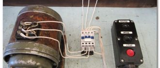
Below is a photo of the input circuit breaker of our air conditioner power supply panel. This is a 3-phase circuit breaker with an independent release S2C-A1 connected to the right side.
It was decided to dismantle this entire facility to find an answer to the question: what could be the matter?
S2C-A1 is disconnected from the machine with little effort. To do this you need to pull them in different directions. To help, insert a slotted screwdriver between them.
It turned out that this independent release acts on the machine only through a thin metal pin that connects their control handles. This is not enough to remotely turn off the machine. Have you tried turning off a 3-pole circuit breaker by hand? This requires strength. Therefore, the machine must be influenced by something else that is not here.
It turns out everything is simple. As people say: “It wasn’t the reel.” There was a small, harmless plastic fork missing. Against the background of these powerful devices, she looks somehow helpless.
Its length is about 16 mm.
This fork must be inserted into both devices into special grooves. On the machine, this groove is initially sealed with a round plug. It can be easily removed with a screwdriver.
I cocked the machine and lightly pressed the mechanism with a screwdriver through the open hole and the machine immediately turned off. Hooray! All that remains is to find such a fork.
As it turned out, it is not sold separately and you only need to buy a new release S2C-A1, which costs about 1250 rubles. It was useless to look for the old one, since it had been in the trash for several months. Where to go - bought it.
The independent release S2C-A1 from ABB is sold in plastic packaging. The fork we need is in the same package, but in a special compartment. Be careful!
You can clearly see it in the bottom photo.
When the installers open the package, the fork flies away and no one has any problems. Something like this! These are our installers!
I don’t understand why during the development of this device it was impossible to provide for its initial attachment to the release. That is, make it so that it is one with this fork and it does not disconnect from it. It already has three pins sticking out. They would have done the fourth one and there would have been no problems. Or at least write a warning on the packaging in large letters: “Attention! There's a little thing inside! Don't lose it!"
Everything is ready for assembly...
This fork has a triple fork on one and a double fork on the other. So, the triple plug needs to be inserted into the machine itself. She sits there well. And the double plug must go into the S2C-A1 release.
It looks something like this...
Snap it on and you're done!
Repeated testing of the independent release with the plug installed showed that the S2C-A1 very easily and quickly trips a powerful three-phase circuit breaker. As you can see, more current is not needed here, as is advised on some forums.
Thank you for your attention!
Let's smile:
Strange people - electricians! They are standing on the ground and looking for land!
Each device that functions as a protective mechanism for electrical networks in the home contains an independent trip for the circuit breaker. Such a device implies a mechanical connection with the switch and is considered built into the machine.
The purpose of this device in an automatic device is to help disconnect the electrical network in the event of an approaching negative factor, such as a short circuit or current leakage from the device itself or household units.
Attention!
Use the equipment strictly within the specified temperature conditions. Deviation from the norm is not recommended
.
In fact, scientists have recorded a large number of cases why the independent release tripped, but the most common and most often encountered in front of you:
- reduction of voltage in the electrical circuit;
- increase in voltage, change in current state;
- changing specified characteristics;
- incomprehensible failure and dysfunction of the machines.
Shunt release
For so many reasons, modern devices are usually equipped with several mechanisms to favorably decouple the network. They are made mainly from electromagnetic and mechanical, sometimes electronic particles. The circuit breaker release will allow you to leave all existing equipment in the household intact. It is customary to divide these built-in devices into two types.
Minimum/overvoltage release type RMM47 (2009)
Continuing the line of devices that protect against the consequences of a break in the neutral conductor, it brings to the market another additional device for circuit breakers of the BA47 series. This is a minimum-overvoltage release RMM47.
This new product has a twist that is not found in other devices: with minimal dimensions, the PMM47 has maximum functionality. In fact, several devices are combined in one housing. This is a minimum release, a maximum release, and when configured for a certain operating mode, PMM47 can perform the function of an independent release.
Purpose and scope
Quote from the passport: “The minimum/overvoltage release type РММ47 ТМ IEK (hereinafter referred to as РММ) is designed to be equipped with automatic circuit breakers of the BA47 series and * performs the function of disconnecting the circuit breaker in the event of an unacceptable decrease or increase in the voltage of the supply network.” That is, in ordinary language, it protects the load if the supply voltage goes beyond the permissible limits for the supply network (which can lead to failure of the powered equipment).
The reasons for deviations beyond the permissible limits may be different, but the most likely reason for their occurrence in residential and office buildings is a break in the neutral conductor at the entrance to the distribution board. The processes occurring in the electrical circuits of consumers have been discussed more than once in the materials of the Vestnik, so we will not dwell on them. Let's move on to the device itself.
According to its characteristics, the RMM47 TM IEK release meets the requirements of technical specifications TU 3429-02318461115-2008 (see Table 1).
The normal operating conditions for the release are:
- range of operating ambient temperatures from -40 to + 50°C;
- altitude above sea level – no more than 2000 m;
- relative humidity 80% at 25°C;
- working position in space – vertical with possible deviation in any direction up to 90°;
- mechanical design group M4 according to GOST 17516.1.
Externally, PMM47, except for markings, is no different from other additional devices from the list for the BA47 modular series, designed for automatic shutdown based on external conditions (shunt release, minimum release, etc.). Those. The overall dimensions and method of connection to the circuit breaker are the same. Each device is equipped with a set of necessary fastening elements, like other accessories. devices.
Installation and operation
Installation and connection of the release must be carried out only by qualified electrical personnel.
Designers must remember that modular equipment is installed in electrical panels with a degree of protection not lower than IP30 according to GOST 14254.
ATTENTION! The release is intended only for operation with single-pole, double-pole, three-pole circuit breakers of types VA47-29, VA47-29M, VA47-100. It is not designed to work with four-pole switches!. РММ47 is equipped with a protection operation indication device (see
rice. 1)
РММ47 is equipped with a protection operation indication device (see Fig. 1).
When the minimum/maximum voltage protection is triggered or when the circuit breaker protection is triggered, the “Return” push button on the front panel of the release goes to the released position and the release blocks the charging mechanism of the circuit breaker. To turn the circuit breaker back on, you must press the “Return” button.
The PMM47 device is made of high quality materials. It has withstood many different testing procedures and has proven its reliability. This makes it possible to indicate the warranty period for the operation of the PMM47 of 5 years from the date of its sale, provided that the consumer complies with the conditions of transportation, storage and operation.
Table 1
Main technical parameters of the release
| Rated operating voltage Ue, V | 230 | |
| Rated operating frequency, Hz | 50 | |
| Operation voltage, V | undervoltage release | 165±10 |
| maximum release | 265±10 | |
| Operating voltage range*, V | 50275 | |
| Types of Compatible Circuit Breakers | one-, two-, three-pole VA47-29, VA47-29M, VA47-100 | |
| Connection side to the circuit breaker | right |
Sudden shutdown of the mechanism
Experts have recorded a lot of cases when the circuit breaker tripped. This situation requires a quick response from the master. To prevent negative consequences, experts have identified the main list of reasons that provoke the mechanism to turn off:
Since there are so many negative factors in the household industry, all modern devices are now equipped with several working mechanisms that allow you to quickly disconnect the network. They are produced from mechanical, electromagnetic or electronic particles. Rational use of such a release helps keep all home appliances safe and sound.