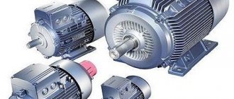
| Stamps | Weight, kg | Motor current, A | Housing protection degree | Overall dimensions, mm, no more | Engine power, kW |
| SUiZ Pilot+ L2 – 25 | 8 | 1…25 | IP 54 | 310x420x150 | 0.3…11 |
| SUiZ Pilot+ L2 – 40 | 8 | 9…17 | IP 54 | 310x420x150 | 9…17 |
| SUiZ Pilot+ L2 — 80 | 11 | 55…80 | IP 54 | 505x300x190 | 22…37 |
| SUiZ Pilot+ L2 – 100 | 16 | 75…100 | IP 54 | 500x400x220 | 30…45 |
| SUiZ Pilot+ L2 — 160 | 25 | 115…160 | IP 54 | 650x500x220 | 45…75 |
| SUiZ Pilot+ L2 — 200 | 27 | 155…205 | IP 54 | 650x500x220 | 75…90 |
Main technical characteristics
| Name | Meaning |
| Rated supply voltage, V / current frequency, Hz | ~380/50 |
| Number of power inputs, pcs. | 1 |
| Permissible deviation of supply voltage from nominal, % | +10 — 15 |
| Maximum current of the connected electric motor, A (depending on version) | 200 |
| Operating temperature range, °C | -40…+40 |
| Shell protection degree according to GOST 14254-80 | IP54 |
| Input for power supply, motor and sensors | at the bottom of the cabinet |
| Type of climate control | U2 |
Brands and characteristics of pumps SUiZ Lotsman+ L2
To scroll a table horizontally, place the cursor over it and use the mouse wheel while holding down the Shift key.
| Stamps | Recommended engine power, kW | Weight, kg | Electric motor current max., A | Housing protection degree | Overall dimensions, mm, no more |
| SUiZ Pilot+ L2 – 25 | 0.3…11 | 8 | 25 | IP 54 | 310x420x150 |
| SUiZ Pilot+ L2 – 40 | 9…17 | 8 | 40 | IP 54 | 310x420x150 |
| SUiZ Pilot+ L2 — 80 | 22…37 | 11 | 80 | IP 54 | 505x300x190 |
| SUiZ Pilot+ L2 – 100 | 30…45 | 16 | 100 | IP 54 | 500x400x220 |
| SUiZ Pilot+ L2 — 160 | 45…75 | 25 | 160 | IP 54 | 650x500x220 |
| SUiZ Pilot+ L2 — 200 | 75…90 | 27 | 200 | IP 54 | 650x500x220 |
The ICS provides protection in the following situations:
- “dry” running (when using an appropriate sensor);
- motor overload – user adjustable in the range 1…300 A;
- engine underload (protection against “dry” running without an additional sensor) – user adjustable in the range of 0.5...299 A;
- incorrect rotation or absence of supply phases (checked when turned on);
- supply voltage is too high or too low – user adjustable in the range 180…245 V;
- phase failure/distortion;
- incorrect operation of level sensors (in automatic mode);
- low insulation resistance of the electric motor - less than 15 kOhm.
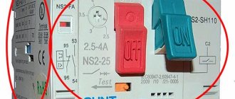
Manual mode
Manual mode is intended for local control of the engine during installation or service work.
The engine is turned on/off only by pressing the “Start”/”Stop” buttons located on the front panel of the MK. The transition to manual mode occurs when the operator changes the value of parameter 1 of the MK setup menu. In manual operating mode, all protections are activated, except for monitoring the correct operation of level sensors. When the protection is triggered, the engine is switched off and the display shows a flashing emergency code with an audible signal until operator intervention. Timers for operating time, on time and off time are not used.
Design and principle of operation
The station consists of a switchboard with a removable mounting panel. Installed inside the shield:
- microcontroller;
- terminal blocks;
- circuit breaker;
- current transformers;
- electromagnetic starter;
- signal LED on the door.
On the panel door there are buttons for controlling the station “Start” and “Stop”. At the top and bottom of the “Lotsman+” control system there are terminal clamps for connecting to the network. There are also clamps for connecting external sensors. On the left side wall of the switchboard there is a hole for installing a station grounding bolt. On the side there are holes for grounding the control station.
Automatic mode based on level sensors
In this mode, the pump motor is automatically turned on/off using discrete pressure or level sensors. Depending on the station function selected by the user, it is possible to automatically maintain the water level in the tank or drain the drainage pit.
Filling function
When the liquid column drops below the low level sensor, the condition of the power supply network, the engine and the correctness of the sensor signals are checked. After this, the pump motor is turned on. During the filling process, currents and voltages are constantly monitored, which must lie within the settings specified in the setup menu. If the values go beyond the set range for a specified time, an emergency shutdown of the electric motor will occur. The indicator will display the error code that occurred and the time until the next engine start. Also during operation, the state of the “External control” input and the state of the “dry” running sensor are checked. When the container is filled to the upper level, the engine will turn off and the MK will proceed to wait for draining.
In automatic mode, the state of the level sensor contacts is constantly monitored.
As soon as a situation arises with incorrect operation of the sensor contacts (for example, the upper level sensor triggered before the lower one), the level LEDs begin to blink and after 2 seconds the protection is activated. The engine turns off and a flashing fault code is displayed on the indicator. The error will be reset automatically after the signals from the sensors are restored.
In automatic mode, additional functions are available, such as an emergency shutdown timer and on/off delay timers.
The emergency shutdown timer is designed to prevent overflow due to the failure of one of the level sensors (for example, there are frequent cases of freezing of upper level sensors on water towers). The purpose of the timer is to turn off the engine after the time specified in the installation menu (in minutes) has passed, if the high level sensor does not operate. The timer starts when the engine is turned on when filling and is reset to zero when the engine is turned off. If the level sensor operates before the timer, the timer stops until the next time the engine is turned on. When the timer is triggered and the restart time has expired after the accident, the station will continue to operate as normal, the MK will wait for the liquid level to drop.
On/off delay timers allow you to ignore false level signals during possible water hammer on long lines that occur after turning the engine on and off. The command to start or stop the engine will be executed only after the pressure surges have stabilized and the sensor contacts have remained in the same state for a user-specified time. Also, using delay timers, it is possible to organize a group (cascade) operation mode of several pumps per storage or drainage tank from common level sensors. The on/off time of each station from the group is adjusted depending on operating conditions for up to 180 seconds.
Drainage function
The operation of the station during drainage is identical to that during filling, with the exception of the reverse order of turning on/off the engine when the liquid level changes. When the liquid reaches the upper level, the engine will start. Once the level reaches the minimum level, the motor will be stopped and the station will wait for the tank to fill to the upper level. As with filling, it is possible to use the delay start, stop and emergency shutdown functions.
The start and stop delay functions for draining are similar to those for filling; the emergency shutdown timer starts with the motor and is reset when the lower level is reached.
Specifications | |||||
| Stamps | Weight, kg | Motor current, A | Housing protection degree | Overall dimensions, mm, no more | Engine power, kW |
| SUiZ Pilot+ L2 – 25 | 8 | 1…25 | IP 54 | 310x420x150 | 0.3…11 |
| SUiZ Pilot+ L2 – 40 | 8 | 9…17 | IP 54 | 310x420x150 | 9…17 |
| SUiZ Pilot+ L2 — 80 | 11 | 55…80 | IP 54 | 505x300x190 | 22…37 |
| SUiZ Pilot+ L2 – 100 | 16 | 75…100 | IP 54 | 500x400x220 | 30…45 |
| SUiZ Pilot+ L2 — 160 | 25 | 115…160 | IP 54 | 650x500x220 | 45…75 |
| SUiZ Pilot+ L2 — 200 | 27 | 155…205 | IP 54 | 650x500x220 | 75…90 |
Main technical characteristics | |
| Rated supply voltage, V / current frequency, Hz | ~380/50 |
| Number of power inputs, pcs. | 1 |
| Permissible deviation of supply voltage from nominal, % | +10 — 15 |
| Maximum current of the connected electric motor, A (depending on version) | 200 |
| Operating temperature range, °C | -40…+40 |
| Shell protection degree according to GOST 14254-80 | IP54 |
| Input for power supply, motor and sensors | at the bottom of the cabinet |
| Type of climate control | U2 |
Control cabinet input signals
| Input name | Signal type |
| Dry running sensor | ~15V |
| Upper level sensor | |
| Low level sensor | |
| "External" control |
Control cabinet output signals
| Output name | Characteristic |
| User-configurable event (selected in the MK setup menu) | NO/NC relay contacts ~250V, 1A |
The control system ensures operation of the pump in the following modes:
- “Manual” - turning on the pump motor from the buttons on the front panel of the controller;
- “Automatic” - control based on a signal from the pressure or level sensor(s).
The ICS provides automatic performance of the following main functions:
- filling/draining of containers based on signals from discrete level sensors of various types (electrode, ECM, float, etc.);
- filling/draining the container using a timer and one of the level sensors (timer time from 1 to 180 minutes);
- filling/draining the container using a pressure switch;
- remote switching on/off of the station engine based on an external control signal.
The ICS provides protection in the following situations:
- “dry” running (when using an appropriate sensor);
- motor overload – user adjustable in the range 1…300 A;
- engine underload (protection against “dry” running without an additional sensor) – user adjustable in the range of 0.5...299 A;
- incorrect rotation or absence of supply phases (checked when turned on);
- supply voltage is too high or too low – user adjustable in the range 180…245 V;
- phase failure/distortion;
- incorrect operation of level sensors (in automatic mode);
- low insulation resistance of the electric motor - less than 15 kOhm.
Manual mode
Manual mode is intended for local control of the engine during installation or service work. The engine is turned on/off only by pressing the “Start”/”Stop” buttons located on the front panel of the MK. The transition to manual mode occurs when the operator changes the value of parameter 1 of the MK setup menu. In manual operating mode, all protections are activated, except for monitoring the correct operation of level sensors. When the protection is triggered, the engine is switched off and the display shows a flashing emergency code with an audible signal until operator intervention.
Timers for operating time, on time and off time are not used.
Automatic mode based on level sensors
In this mode, the pump motor is automatically turned on/off using discrete pressure or level sensors. Depending on the station function selected by the user, it is possible to automatically maintain the water level in the tank or drain the drainage pit.
Filling function
When the liquid column drops below the low level sensor, the condition of the power supply network, the engine and the correctness of the sensor signals are checked. After this, the pump motor is turned on. During the filling process, currents and voltages are constantly monitored, which must lie within the settings specified in the setup menu. If the values go beyond the set range for a specified time, an emergency shutdown of the electric motor will occur. The indicator will display the error code that occurred and the time until the next engine start. Also during operation, the state of the “External control” input and the state of the “dry” running sensor are checked. When the container is filled to the upper level, the engine will turn off and the MK will proceed to wait for draining.
In automatic mode, the state of the level sensor contacts is constantly monitored.
As soon as a situation arises with incorrect operation of the sensor contacts (for example, the upper level sensor triggered before the lower one), the level LEDs begin to blink and after 2 seconds the protection is activated. The engine turns off and a flashing fault code is displayed on the indicator. The error will be reset automatically after the signals from the sensors are restored.
In automatic mode, additional functions are available, such as an emergency shutdown timer and on/off delay timers.
The emergency shutdown timer is designed to prevent overflow due to the failure of one of the level sensors (for example, there are frequent cases of freezing of upper level sensors on water towers). The purpose of the timer is to turn off the engine after the time specified in the installation menu (in minutes) has passed, if the high level sensor does not operate. The timer starts when the engine is turned on when filling and is reset to zero when the engine is turned off. If the level sensor operates before the timer, the timer stops until the next time the engine is turned on. When the timer is triggered and the restart time has expired after the accident, the station will continue to operate as normal, the MK will wait for the liquid level to drop.
On/off delay timers allow you to ignore false level signals during possible water hammer on long lines that occur after turning the engine on and off. The command to start or stop the engine will be executed only after the pressure surges have stabilized and the sensor contacts have remained in the same state for a user-specified time. Also, using delay timers, it is possible to organize a group (cascade) operation mode of several pumps per storage or drainage tank from common level sensors. The on/off time of each station from the group is adjusted depending on operating conditions for up to 180 seconds.
Drainage function
The operation of the station during drainage is identical to that during filling, with the exception of the reverse order of turning on/off the engine when the liquid level changes. When the liquid reaches the upper level, the engine will start. Once the level reaches the minimum level, the motor will be stopped and the station will wait for the tank to fill to the upper level. As with filling, it is possible to use the delay start, stop and emergency shutdown functions.
The start and stop delay functions for draining are similar to those for filling; the emergency shutdown timer starts with the motor and is reset when the lower level is reached.
Automatic mode based on timer and upper (lower) level sensor.
This mode is provided for conditions where installing an upper level sensor is not possible (for example, on water towers in severe frosts it freezes and, accordingly, fails), and the use of an electric contact pressure gauge is difficult for some reason. In this case, only one level sensor is installed, which, when triggered, fills/drains the container within the time required for filling or draining. The upper level sensor is not used in this mode. The filling or draining function is selected in the MK setup menu. When filling, the input of the lower level sensor is used, when draining, the input of the upper level sensor is used.
When filling
If the sensor is open, which means there is no liquid in the container, then the pump motor is turned on for a period of 1 to 180 minutes (changed by the user in the setup menu). The filling time for a specific container is selected by trial in manual mode. After the filling time has ended, the MK will wait for the lower level sensor to open, and after that it will repeat the filling cycles again.
When draining
If the sensor is in a closed state, which means the tank is full, then the engine is turned on for a period of time from 1 to 180 minutes. The drainage time for a specific container is selected by trial in manual mode. After the drain time has ended, the MK will wait for the low level sensor to close, and after that it will repeat the drain cycles again.
As in all other modes, all used protection parameters are checked before starting and during engine operation.
Remote control of engine operation
Remote control is possible using the “External control” input of the station. This input must be enabled in the MK setup menu. In automatic modes, closing this input allows the station to operate in this mode, opening it prohibits operation. The engine will only be turned on when the level sensors are triggered according to the mode and function used. Restart after an emergency will occur automatically after the specified delay time has elapsed.
In manual mode, when the input is closed, the electric motor starts immediately, and when it opens, it turns off. After the protection is triggered, the engine will be turned off and a flashing fault code will remain on the indicator. Resetting the accident and restarting when the “External control” input is activated - opening this input or pressing the “Stop” button of the MK. The alarm will be reset and, depending on the input status, the engine will be turned on/off.
When the “External control” input is activated, the “Start” and “Stop” buttons of the MK are blocked.
Remote transmission of operating signals
For remote transmission of signals to the dispatch console or automated process control system, the station uses an electromagnetic relay K2 of the controller with a changeover contact.
The relay contacts close depending on the selected condition in a special item in the MK setup menu. The following relay activation options are available:
- station operation;
- station accident;
- engine on/off;
- input state “External control”;
- state of the “Upper level sensor” input;
- input status “Lower level sensor”;
- state of the “Dry running sensor” input.
If necessary, you can receive a “Motor on/off” signal using an additional NO contact located in the contactor.
You can learn more about the operation of the station in the documents “L2 Programming Guide” and “Lotsman+ L2 Operation Guide”.
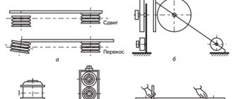
Using different types of level sensors
Symbol
For example, SUiZ Pilot+ L2-25-IP54-U2 TU 3432-112-00217975-2011 , where:
- Pilot+ L2 – control and protection station L2;
- 25 – maximum operating current of the connected electric motor, A;
- IP54 – degree of protection of the shell according to GOST 14254-96;
- U2 – climatic version and placement category.
Automatic mode based on timer and upper (lower) level sensor.
This mode is provided for conditions where installing an upper level sensor is not possible (for example, on water towers in severe frosts it freezes and, accordingly, fails), and the use of an electric contact pressure gauge is difficult for some reason. In this case, only one level sensor is installed, which, when triggered, fills/drains the container within the time required for filling or draining. The upper level sensor is not used in this mode. The filling or draining function is selected in the MK setup menu. When filling, the input of the lower level sensor is used, when draining, the input of the upper level sensor is used.
When filling
If the sensor is open, which means there is no liquid in the container, then the pump motor is turned on for a period of 1 to 180 minutes (changed by the user in the setup menu). The filling time for a specific container is selected by trial in manual mode. After the filling time has ended, the MK will wait for the lower level sensor to open, and after that it will repeat the filling cycles again.
When draining
If the sensor is in a closed state, which means the tank is full, then the engine is turned on for a period of time from 1 to 180 minutes. The drainage time for a specific container is selected by trial in manual mode. After the drain time has ended, the MK will wait for the low level sensor to close, and after that it will repeat the drain cycles again. As in all other modes, all used protection parameters are checked before starting and during engine operation.
Deciding on implementation
So, let's assume that you are one of the managers of a company or organization. The design and technology departments, production, supply, sales, accounting, personnel department and other departments are under your control. The enterprise is already automating the activities of individual services. Your designers use KOMPAS-3D and SolidWorks for three-dimensional design, prepare drawings in KOMPAS-Graph, technologists actively use KOMPAS-Avtoproekt, accounting keeps records in 1C:Enterprise, and in the shops they use automated systems for calculating cutting and welding modes. Everything is pretty good, but for some reason the effect of introducing automation was not as significant as expected.
Recently, it is increasingly happening that your company needs to quickly rebuild production to produce new products. But for now, the designers will release the documentation, hand it over to the technologists for approval, then work out the comments and hand it over again for the preparation of technological documentation, and then to the suppliers, economists - lo and behold, the competitors are already ahead... And most importantly, so much money has been invested in this automation! What's the matter?
One of the few economically and technologically beneficial ways to get out of this situation is the creation and use of a unified information environment at the enterprise, its transparency (of course, subject to compliance with the restrictions on access to information!), as well as the parallel execution of work by many specialists during design and technological preparation production. The tool for implementing all these tasks is LOTSMAN:PLM. This system is designed to accumulate production and management information, provide it to engineering services in accordance with the rules defined at the enterprise, and ensure the exchange of tasks between departments and specialists. Of course, we are talking about information presented in electronic form, data exchange between the components of a single software package. Such, for example, is a complex, in addition to LOTSMAN:PLM, which includes:
• automation systems for design preparation of production KOMPAS-3D and KOMPAS-Graph;
• automation system for technological preparation of production KOMPAS-Avtoproekt;
• a set of unified databases (directories) of the LOTSMAN series, which can be accessed by other components of the complex.
Work with documentation in LOTSMAN:PLM is based on the requirements of industry standards.
Remote control of engine operation
Remote control is possible using the “External control” input of the station. This input must be enabled in the MK setup menu. In automatic modes, closing this input allows the station to operate in this mode, opening it prohibits operation. The engine will only be turned on when the level sensors are triggered according to the mode and function used. Restart after an emergency will occur automatically after the specified delay time has elapsed.
In manual mode, when the input is closed, the electric motor starts immediately, and when it opens, it turns off. After the protection is triggered, the engine will be turned off and a flashing fault code will remain on the indicator. Resetting the accident and restarting when the “External control” input is activated - opening this input or pressing the “Stop” button of the MK. The alarm will be reset and, depending on the input status, the engine will be turned on/off.
When the “External control” input is activated, the “Start” and “Stop” buttons of the MK are blocked.
Application
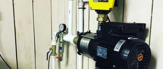
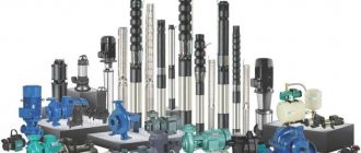
- to ensure control, monitoring and protection of pumps (submersible/centrifugal), which are used in water utilities, in housing and communal services structures;
- to ensure monitoring and control of pumps (submersible/centrifugal) operating in water supply/sewage systems of industrial enterprises;
- in agriculture for control and protection of pumps (submersible/centrifugal) involved in irrigation systems for farmland;
- in pressure boosting systems of residential and industrial facilities;
- at thermal power facilities to ensure control, monitoring and protection of pumps (submersible/centrifugal) involved in the process water supply system;
- automatic drainage of the drainage pit using level sensors;
- at production facilities to ensure control, monitoring and protection of components and mechanisms that use three-phase asynchronous electric motors.
Remote transmission of operating signals
For remote transmission of signals to the dispatch console or automated process control system, the station uses an electromagnetic relay K2 of the controller with a changeover contact.
The relay contacts close depending on the selected condition in a special item in the MK setup menu. The following relay activation options are available:
- station operation;
- station accident;
- engine on/off;
- input state “External control”;
- state of the “Upper level sensor” input;
- input status “Lower level sensor”;
- state of the “Dry running sensor” input.
If necessary, you can receive a “Motor on/off” signal using an additional NO contact located in the contactor.
You can learn more about the operation of the station in the documents “L2 Programming Guide” and “Lotsman+ L2 Operation Guide”.
Tailored to your company: system adaptation
After installation and initial configuration of the system, you need to adapt LOTSMAN:PLM to work at your enterprise - fine-tune the databases.
Enterprises and organizations in their daily activities are subject to the requirements for production documentation by state and industry standards. For designers this is SPDS (System of Design Documentation for Construction) and SNiP (Building Norms and Rules), for mechanical engineers - ESKD (Unified System of Design Documentation) and ESTD (Unified System of Technological Documentation), etc.
Naturally, the data structure in LOTSMAN:PLM is built in accordance with these requirements. Each database in the system is based on an initial configuration, which is a set of user groups, types of objects and documents, their properties, states and relationships - objects and concepts, using which you can model work with documentation and production objects. This set is called metadata.
The basic set of metadata takes as a basis the industry standard and determines the scope of application of the system, as well as the rules for document flow within it, which, in essence, initiates the emergence of a new member of the LOTSMAN family - “LOTSMAN Mechanical Engineering”, “LOTSMAN SPDS” or “LOTSMAN PKO” (Project design department), etc. Any of them is an independent software product, has an individual set of functionality and operates with a certain set of objects of the material world, for example, in “LOTSMAN Mechanical Engineering” these are parts, assembly units, technologies, tools, etc.; “LOTSMAN SPDS” uses construction objects, sections, stages, etc.
Metadata tree of the “LOTSMAN PKO” database
At the same time, the fundamental principles of working with the system, regardless of the basic settings, are common. This makes it possible to talk about LOTSMAN:PLM in general. For example, if we consider the option of deploying LOTSMAN:PLM at a machine-building enterprise, then when creating the database, the administrator has already included in it all the necessary descriptions and properties of assembly units, parts, sets of drawings, etc. However, within the boundaries of industry regulations there are often features of record keeping and execution that may not be covered by the basic set of metadata. For example, some designers combine their main activities with regulatory control functions, and all products have, in addition to the main one, an additional number used within the enterprise.
To take into account all these nuances and make working in the system convenient for specialists, it is necessary to adapt the metadata. This can be easily done by a specialist, whom we have previously identified as an experienced user, since setting up metadata does not require knowledge of programming techniques. Only the system administrator and the user to whom he has given this right—the database administrator—can edit metadata.
The database metadata is presented in the form of a tree, which makes it easy to navigate the structure and quickly find the necessary objects.
When setting up metadata, a second level of information protection is provided in the database. It involves uniting users performing similar production functions into groups and determining for them the range of available information and the level of access to it. This applies to both production objects (for example, assembly units, equipment, drawings, route elements) and their individual characteristics. The designer, as a rule, does not need the codes that the shop workers operate, and office workers do not need access to information about the products being designed, etc.
In addition, user groups can be allowed or prohibited from creating specified types of objects and documents, or giving them certain characteristics.
Access rights assigned when setting up metadata can be overridden directly when working with data, but to do this you need to have the appropriate permissions, which are also given when setting up the database.
Centralized management of access rights to metadata allows you to avoid arbitrary changes to documentation in conditions of collaborative work with information.
After setting up the metadata, it’s time to fill new databases with information that was previously accumulated by your employees in various data management systems. Here again you will have to involve a system administrator or specialist who knows well the structure of the database from which the import will be performed, as well as:
• knowledgeable about the basics of programming, algorithmization, SQL;
• having an understanding of XML as a data presentation format.
This employee, using the tools provided by LOTSMAN:PLM, will be able to create an algorithm for importing data from any system that can be accessed through the ODBC interface into XML documents in the LOTSMAN system format, and then perform data transfer.
If you have previously used the KOMPAS-Manager project and electronic archive management system, popular among mechanical engineers, then your employee will be able to use a ready-made algorithm for importing data from the KOMPAS-Manager database into the LOTSMAN:PLM database, which is supplied with the system. This algorithm will help you quickly and without data loss convert accumulated information, including notices, technical processes, correspondence, and developments into LOTSMAN:PLM. Its use when moving to a more modern data management system will save both the time of the system administrator and the nerves of users who will see all their work materials in the new database.
Now the system is ready for work, filled with data, and now is the moment when the enterprise will finally be able to fully take advantage of all the advantages and opportunities inherent in LOTSMAN:PLM.
Setting up metadata in LOTSMAN:PLM