Hi all. Recently a client called me with a problem: the computer would not turn on at all. I immediately understand that the problem may be in the power supply. Therefore, I make sure to take a tester and a new power supply with me for replacement.
But there are times when the computer turns on, but does not work stably: it suddenly turns off, then reboots. How to be in this case?
In this article I will tell you how to check a computer's power supply with a multimeter, a tester and a special program under load.
Checking the startup of the power supply without a computer
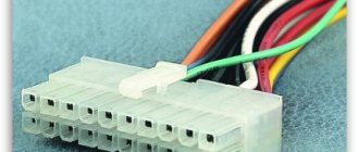
This test of the computer power supply is convenient because it does not require the presence of the PC itself. All you need is a socket, a multimeter and a regular paper clip. So, we have an ATX power supply in our hands. We find a wiring harness ending in a 24-pin connector. This is the largest PSU connector, and it won’t be difficult to find.
On this block we find a green wire and, using an unbent paperclip inserted into the corresponding sockets, we connect it with any black one, thereby simulating the motherboard command to “turn on the power supply.”
These two contacts need to be closed
Now we connect the power supply to the network: if it is working properly, it should start. This will be clearly audible through the noise of the cooling fan running. But such a check cannot give a full or even partial guarantee that the power supply is fully operational. Therefore, we arm ourselves with a multimeter and move on to the next point.
Current measurement
Having a general understanding of the operation of the current source, you can begin to check it. If we are talking about power supplies for phones, cameras and other low-power equipment with small blocks, then the current in them can be measured.
How to measure current strength is a question in a school textbook. A multimeter or ammeter is connected to the open circuit. Please pay attention to the limit value of the scale. If the multimeter allows you to measure a maximum of 10 A, then you can check a unit designed for a maximum of this current, and no more. Our current will be constant, since it has already passed through the block.
To connect the power supply, you must either cut one of the wires or disassemble the case. The circuit must be closed to the tester. Measurements are carried out quickly, within 2 seconds, so that the contacts do not have time to heat up too much.
Checking with a multimeter
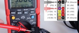
Almost any multimeter (tester) capable of measuring DC voltages up to 15 V with an accuracy of 0.1 V is suitable for measurements. It can be either pointer or digital.
This multimeter is quite suitable for our needs.
We set the device to measure DC voltage with a limit of 15-20 V and insert one of its probes into the motherboard connector socket to which the black wire is connected. There are several such nests on the block; any one will suit us. Using the second probe, we alternately touch the sockets to which the red, yellow, orange, blue and purple wires are connected. These are the power supply buses +5 V, +12 V, +3.3 V, -12 V and +5 V, respectively.
Measuring voltage on the standby bus +5 V (purple wire)
We compare the measurement results with the values indicated in the table below. As can be seen from the photo, the actual voltage on the +5 V standby bus is within the permissible range.
ATX power supply voltage table
| Voltage, V | Allowable spread, V | Wire color | Contact | Contact | Wire color | Voltage, V | Allowable spread, V |
| +3.3 | +3,14 … +3,47 | orange | 1 | 13 | orange | +3.3 | +3,14 … +3,47 |
| +3.3 | +3,14 … +3,47 | 2 | 14 | ||||
| 3 | 15 | blue | -12 | +10.8 … +13.2 | |||
| +5 | +4,75 … +5,25 | red | 4 | 16 | |||
| 5 | 17 | ||||||
| +5 | +4,75 … +5,25 | red | 6 | 18 | |||
| 7 | 19 | ||||||
| 8 | 20 | ||||||
| +5 | +4,75 … +5,25 | violet | 9 | 21 | red | +5 | +4,75 … +5,25 |
| +12 | +11,4 … +12,6 | yellow | 10 | 22 | red | +5 | +4,75 … +5,25 |
| +12 | +11,4 … +12,6 | yellow | 11 | 23 | red | +5 | +4,75 … +5,25 |
| +3.3 | +3,14 … +3,47 | orange | 12 | 24 |
Important! The standby voltage +5 V must be present even when the power supply is not running, but is connected to the electrical network (the paper clip is not installed).
If all the voltages indicated in the table on the ATX connector are normal, check their presence on the remaining pads intended to power the processor, additional video card and other peripherals. The color matching of the wires to the voltage on these blocks is the same as on the main one, so we use the same table as a guide.
Now the picture is clearer: our power supply is most likely working. But it’s not clear, since under load the output voltages may change. In order to be completely sure that the power supply is working properly, you need to load it. Let's try to do this without using a PC.
Finding the cause of the malfunction
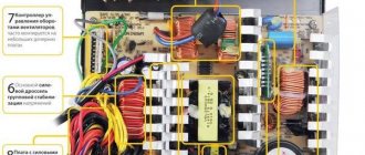
If there is no voltage or the values are outside the tolerance limits, you need to look for the reason for this in the power supply. To do this, you need to remove it from the system box. On the back cover, the screws holding the power source housing are unscrewed, and it is removed. Then you need to remove the protective cover of the power supply.
After this, visual inspection is carried out, the presence of carbon deposits and swelling of the capacitors is checked. Batteries with such symptoms must be replaced. Further testing begins with a continuity test of the circuit in which there is no voltage.
The multimeter switches to the resistance measurement position. In this mode, the network cable must be disconnected from the power supply. One probe is connected to the contact of the connector with no potential, the second to the point where the wire is connected to the board and a measurement is made. The device should show 0 Ohm. This means that the conductor is intact. If the values are non-zero, then it needs to be replaced.
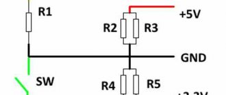
Load diagram for all lines
So, in order to carry out a complete diagnosis of the power supply, it is necessary to load the power buses with at least half the power of the power supply. We are especially interested in the +12 V, +5 V and +3.3 V lines. First, let’s assemble a simple device:
This device uses its own set of resistors to load each of the lines, connected to the corresponding contacts of the motherboard power supply. As for the number of resistors in each set, everything will depend on how much current we want to load each line. Knowing the voltage on the bus and the resistance of the resistors (different on each line, see diagram), it is easy to calculate that each additional resistor on the +12 V bus will increase the current by 12 / 5.1 = 2.35 A. For the +5 V and + 3.3 V lines this will be 5 / 1.6 = 3.1 A and 3.3 / 1.0 = 3 A, respectively.
Thus, if we decide to load the +12 V bus with a current of 10 A, then we will need 10 / 2.35 = 4 resistors with a nominal value of 5.1 Ohm (see diagram). A current of 12 A on the +5 V bus can be obtained by connecting 4 resistors with a nominal value of 1.6 Ohms.
How to operate the device? We connect the required number of load resistors to the corresponding sockets of the power supply, install a paper clip, give the start command (see the previous section), and turn on the power supply to the network. After the fan rotates (if it rotates), we measure the voltage on all buses, as we did without load.
We “drive” our power supply for 5-10 minutes, repeating the measurements and monitoring the temperature of the air blown out by the fan. At half load the air should be slightly warm. If the voltage values are within the permissible range, then you can be sure that the power supply is working and will not let us down.
Expert opinion
Alexey Bartosh
Specialist in repair and maintenance of electrical equipment and industrial electronics.
Ask a Question
Important! If we want to test a powerful power supply, then we will need currents that the ATX block simply cannot withstand, since it only has 2 wires of the +12 V bus. In this case, we connect the yellow wires of the processor and video card power blocks parallel to the yellow wires of the ATX block.
As we have seen, the device is quite simple to repeat, but if we need it more than once, then using it is not entirely convenient. A power supply of a different power will appear, and the load currents will need to be changed. To do this, you will have to recalculate the number of resistors in each channel and pick up a soldering iron.
Therefore, if we plan to work with the device often, then it makes sense to modify it. The modification scheme is not particularly complicated, but using such a tester is much more convenient and safer for the power supply itself, since nothing will hang “on the snot”, there will be no paper clips or bad contacts that can burn out the power supply pads. In addition, with the help of such a tester we will be able to monitor the presence of all voltages and signals visually.
Scheme of a full-fledged power supply tester
Here, each channel is also loaded with groups of resistors, but if desired, some of them can be turned off by simply flicking a switch. The diode assembly D1 prevents the flow of current from bus to bus - this made it possible to get by with just one toggle switch S2. To visually monitor the presence of voltage on all buses, indicator lamps X1-X6 have been added to the circuit. At the same time, light bulbs on low-power buses -5 V, -12 V and +5V SV are simultaneously load-bearing.
The role of a paperclip giving the command to turn on the power supply is now played by switch S1. And the PG signal (power is normal), generated by the power supply, is indicated by an LED connected through transistor T1 to the corresponding contact of the ATX block. The Fan, connected to the +12 V circuit, serves to cool the load resistor cassettes, which will heat up during prolonged operation.
Thanks to this design, the device can be connected to the power supply via 1 ATX connector. True, to do this you will have to find the appropriate socket into which the plug of the power supply being tested will be inserted. Alternatively, it can be removed from the faulty motherboard.
Working with the device is as simple as possible. Set toggle switch S2 to the desired mode (see table below). We connect the tested power supply to the ATX socket of the tester, plug it (the unit) into the socket. We close switch S1, the power supply starts. The presence of voltage along the lines and the PG signal is monitored visually. If everything is lit and glowing, you can pick up the tester and take measurements.
Table of currents by lines depending on the position of switch S2
| Tire | Current at switch position S2, A | |
| 150 W | 250 W | |
| +12 V | 7.5 | 12.2 |
| +5 V | 6.4 | 12.6 |
| +3.3 V | 6.6 | 13.3 |
| -5 V | 0.22 | 0.22 |
| -12 V | 0.22 | 0.22 |
| +5V SV | 0.72 | 0.72 |
Expert opinion
Alexey Bartosh
Specialist in repair and maintenance of electrical equipment and industrial electronics.
Ask a Question
Perhaps the only inconvenience of working with such a device is the lack of a built-in voltmeter. But if desired, this problem can be solved. To do this, it is enough to integrate a voltmeter with a measurement limit of up to 15-20 V and a biscuit switch into the circuit.
According to the tester details. Load resistors must be wirewound with a power of at least 15 W for the +12 V bus and 10 W for the remaining buses. Switch S2 must withstand a current of at least 25 A. It can be found in an auto shop. Transistor T1 – any low-power silicon, npn structure. LED - any indicator light. Toggle switch S1 is also any. Fan – 12-volt cooler from the same power supply or similar. The Schottky diode assembly D1 can be taken from a faulty power supply. It is located in the rectifier on the 5 V bus.
Checking with a special tester
How to check the computer's power supply for functionality if we have no knowledge of radio engineering and don't know how to solder? Limit yourself to simple voltage measurement? But, firstly, such a check will be incomplete. Secondly, using a multimeter requires understanding at least the basics of electrical engineering. But it turns out that you don’t have to make a tester - you can buy it. At least that's what they say. Let's check how true this information is and whether you can really buy a high-quality computer power supply tester for real money. We go online and start searching.
Power supply tester LCD
A relatively inexpensive and easy-to-use tester allows you to quickly measure voltages on the +12 V, +5 V, +3.3 V, +5 V SB and – 12 V buses, as well as the presence of a PG signal and the delay time for its appearance after the power supply starts. During measurement, the device independently monitors the voltage values and checks whether they fall within the permissible ranges. Using the Power supply tester, you can check the presence of voltages both on the main ATX connector and on the additional ones that supply the processor, video card, SATA and IDE peripherals.
In the photo the numbers indicate:
- 1 – socket for connecting the power cable for an 8-pin video card or 4-pin processor;
- 2 – socket for connecting a 6-pin video card power cable;
- 3 – socket for connecting the NGMD power cable;
- 4 – LED indicators of voltage presence on sockets 1, 2, 3, 7, 5;
- 5 – socket for connecting the power cable to SATA devices;
- 6 – LCD display;
- 7 – socket for connecting the power cable for IDE devices (MOLEX);
- 8 – socket for connecting the motherboard power cable (ATX).
Let's briefly look at the device's operating algorithm. We connect the main ATX power connector to the tester and, if necessary, the others that need to be checked. We plug in the power supply itself and it starts automatically. In this case, the LCD display of the tester displays the voltage values on all buses of the ATX connector and the delay time for turning on the PG signal.
If any parameter is out of range, an error message is generated for the corresponding channel. The presence of voltage on additional connectors is indicated by LED indicators. If they (connectors) are not connected, there is no indication.
Checking the computer power supply using a tester
Important! The device receives power from the ATX block and runs the power supply through it. Therefore, even if you need to test, say, a SATA connector, the ATX connector will have to be connected.
What can you say about this device? Convenient, simple, clear. It is inexpensive - around $10. But it measures voltages without load. Thus, it will not be possible to test the power supply 100%.
Kingwin KPST-02
This tester performs the same functions as the previous model, but it keeps the measurement results to itself, reporting only that such and such voltage is either normal or present. In addition, the device does not measure the delay time of the PG signal.
We work with it in the same way as with Power supply testerLCD. We connect the power supply pads, turn on the power supply to the network. It starts up, and we admire the light bulbs and wonder whether the voltage is normal or whether it is simply present, but it is not known whether it is within the permissible range.
It seems to work, but I personally wouldn’t trust the LEDs. Moreover, the description does not contain information that the device controls not only the presence, but also the magnitude of voltages. And if it is not specified, then either the marketers are asleep, which is unlikely, or no one controls anything. You will have to pick up a voltmeter and check all voltages. And if you need to tinker with a multimeter, why do you need such a tester? After all, he takes measurements without a power supply load. But there is also a plus - this tester costs half as much as the previous model.
Power supply device
To identify a malfunction, you need to have a general understanding of the purpose and design of the electric current source.
Currently, two types of power supplies are used: transformer and switching. The first ones, using a step-down transformer, convert alternating current 220 volts 50 hertz into the voltage of the required value. Then it is rectified through a diode bridge, and capacitors and transistors convert it into direct current.
The second, with the help of high-voltage diodes, alternating 220 volts are first rectified, passed through a filter and converted into a pulse current with a frequency of (30-200) thousand hertz. After this, the high-frequency voltage is supplied to the transformer, and the required potential emerges from the secondary windings. Further conversion proceeds as in a transformer power supply.
Pulse current sources have become widespread due to their smaller dimensions and the same power.
Transformers are needed for the safety of people and to protect batteries from high voltage.
Let's sum it up
So, we found out that it is not easy to qualitatively test a computer’s power supply, but it is quite possible. True, for a full check you will need some knowledge of the basics of electrical engineering and additional equipment. Unfortunately, it seems that you will have to assemble this equipment yourself, since what you managed to google cannot be called full-fledged testers. Beautiful, visual, simple, but, unfortunately, ineffective. Of course, real industrial testers exist, but, alas, they don’t cost a penny, and we won’t buy them for occasional use.