Modern power supplies
Today's power supplies are somewhat different from their predecessors, not only with modern designs, increased power and improved performance, but also with new connectors for devices that were not previously found in most conventional computers. This is due to the development of new devices or modification of old ones, increasing the technical characteristics of existing ones and, as a consequence, the need for additional power.
In addition to conventional power supplies, there are modular or partially modular units. The difference between the blocks is that in modular ones, in whole or in part, the cables are replaced with appropriate connectors for connecting them and fully comply with the connector standards of conventional blocks. This is good because unused wires will not be in the computer case and interfere with its modernization, as well as with the air circulation inside.
There are certification standards for the energy efficiency and efficiency of a standard power supply, to measure the efficiency of power delivery and distribution of power to the computer's internal devices. It is the consumption of additional power that causes the appearance of new connectors, the presence of additional wires and contacts.
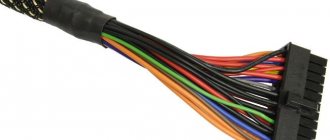
Modern power supplies still contain the basic connectors used in earlier models, supplying devices with the standard voltage of 12, 5 and 3.3 volts. So, to connect to the motherboard, a 24 pin connector is used (from the English pin - pin, contact), which has undergone some changes. In older models of motherboards, and accordingly in power supplies, a 20 pin connector was used. Therefore, in most modern PSUs (power supply units), the connector is made in the form of a collapsible model, which is a standard 20 pin connector + an additional 4 pin connector for modern motherboard models.
When using only 20 pin, the additional 4 pin connector is removed (slides down along the plastic rails) and remains separately in reserve. Further, the power supply necessarily contains molex type connectors (after the name of the company that developed Molex) in 4 pin, for “powering” optical drives and other types of drives with the PATA (Parallel ATA) interface, replaced by the more modern SATA (Serial ATA) interface. To power SATA drives, there are usually two special 15 pin connectors (or PATA HDD –> SATA HDD power adapters).
And also in a modern power supply there should be power connectors for the central processor 4 or 8 pin (can be collapsible), a connector for powering the video card (6/8 pin, can also be collapsible and contain 6 pin + 2 separate contacts). Some models may have a Floppy connector (4-pin) to power floppy drives, some card readers and other devices that use this outdated connector.
What is it and what is it eaten with?
Many computer components have names that require a bit of technical knowledge to understand what they are and why (for example, a solid-state drive), but in the case of a power supply, everything is pretty obvious. This is the unit that provides power.
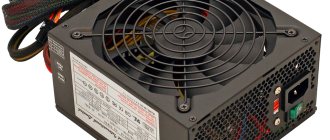
But we cannot put an end to this, proudly declaring “the article is ready.” Our series of articles is devoted to the internal structure, and on the operating table we have a test subject - the Cooler Master G650M. This is a fairly typical representative, with characteristics similar to dozens of other models, but it has one feature that is not found in all power supplies.
Official photo of the Cooler Master power supply.
This is a standard size power supply that fits the ATX 12V v2.31 form factor, making it suitable for many computer cases.
There are other form factors - for example, for small cases, or completely unique ones upon special order. Not every block corresponds to the exact dimensions established by standard form factors - they may be the same width and height, but differ in length.
This power supply from Cisco is specially designed for server racks
PSU markings usually indicate their main parameter - the maximum power provided. In the case of our Cooler Master, this is 650 W. Later we will talk about what this actually means, but for now we will just note that there are also less powerful power supplies, since not all computers require exactly that much, and some need even an order of magnitude less. But still, most desktop computers are provided with power in the range from 400 to 600 W.
Power supplies like ours are assembled in rectangular, often unpainted, metal cases, which is why they are quite heavy. Laptops almost always have an external power supply, in a plastic case, but its internals are very similar to what we will see in the power supply we are considering.
Photo source nix.ru
Most typical power supplies are equipped with a power switch and a cooler for active thermal regulation, although not all power supplies need it. And not all of them have a ventilation grill - in server versions, in particular, this is rare.
Well, as you can see in the photo above, we are already armed with a screwdriver and are ready to start opening our copy.
Computer power supply pinout - how it works
The power supply for a desktop computer is designed to convert alternating voltage 220v into reduced direct voltage with a nominal value of ±12v, ±5v, +3.3v. Power supply ±12v is used to operate connected computer components, usually the cooling system and drives. All microcircuits installed on the motherboard receive power via ±5v, +3.3v buses.
The pinout of the computer power supply from early years of production is not fundamentally different from modern power supplies. Of course, the current generation of power supplies are equipped with connectors for modern components.
Peculiarities
It's no secret that modern power supplies (PSUs) have become more powerful, have improved characteristics and, of course, a modern design than their predecessors 10-15 years ago. Also, many of you know (or are learning now) that modern power supplies have new connectors for components not previously used in personal computers (PCs). The presence of new connectors is associated with the emergence of new (or modernization of old) computer components, improvements in their performance characteristics and, as a result, the need for additional power.
A modern power supply meets energy efficiency and efficiency certification standards that are used to distribute power and efficiently deliver power to computer components. Due to the “greater gluttony” in power supply of the same video cards and motherboards, the power supply contains additional wires, contacts and connectors.
PSU connectors
The power supply contains the main connectors (electrical connectors) previously used in old power supplies, supplying voltages of 3.3, 5 and 12 Volts. Each connector pin is one Pin.
The motherboard is connected to the power supply via a 24 Pin male connector (the so-called bus), which has undergone changes with the improvement of motherboards. Previous generations of motherboards were connected to the power supply via a 20 Pin bus.
Because of this, in order to support any type of connection to the motherboard, the connector is made in the form of a collapsible design with a 20 Pin main and 4 Pin additional power connector.
If the motherboard only needs 20 Pin, the 4 Pin connector is removed (pull down along the plastic rails) and bent to make it easy to install a 20-pin bus.
To power optical drives and other drives with a PATA (Parallel ATA) connection interface, molex 8981 connectors (named after the manufacturer's company) are used.
Now they have been replaced by the modern SATA (Serial ATA) connection interface for drives of all types.
The central processor requires power from a 4 or 8 Pin connector (can be detachable).
The video card needs 6 or 8 Pin power. The connector can be dismountable to 6+2 Pin
Some modern power supplies may contain an outdated 4 Pin connector for floppy drives, card readers, etc.
Also, 3 and 4 Pin connectors are used to connect coolers.
Pinout of the main power cable connector
The pinout of a computer's power supply starts with the largest and most important power cable - this is the cable connected to the motherboard. On old-style motherboards, the ATX connector is designed for 20 pins, while new generation motherboards already contain 24 pins in their connector. It is for this reason that new generation power supplies have cables with a 20+4 pin plug.
When pinouting a computer's power supply, it is important to know that the ATX plug is only suitable for powering the motherboard. This can be checked by looking closely at the contacts in the plug and connector - each of them is unique and suitable for only one purpose.
Computer power supply pinout under load
To check the functionality of the power supply, you can connect it without affecting the system as a whole. This is done so that in the event of a defective power supply, all components of the computer are not damaged. To start the power supply for the first time, you need to close contacts 6 and 7. If everything is done correctly, the power supply should signal an operation in the form of a spinning fan.
Note: Pin counts do not include the additional four pins for the ATX connector.
Power pinout for SATA
To update the IDE interface, a new SATA cable was introduced, which contained 15 pins. A total of five wires are connected to the plug, each of which occupies three contacts. The first three orange contacts operate with a voltage of 3.3 volts. The second three are COM contacts, that is, “ground”. The middle pins have an input voltage of 5 volts. The fourth triple is identical to the second. The last three contacts are already with a voltage of 12 volts.
Older versions of this cable had four wires of three pins, but with the interface update, support for 3.3 volt input voltage was added, which is indicated by the orange wire.
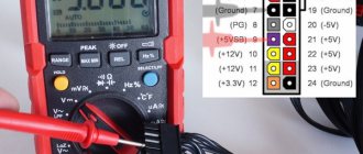
15-pin SATA power connector pinout
A pinout is an interface map that describes the pins that connect an electrical device or connector.
Below is a diagram of the layout of a standard 15-pin SATA power connector for version 2.2 of the ATX specification. If you use this pin chart to test power supply voltages, keep in mind that these voltages must be within ATX tolerances.
15-Pin SATA Connector Reference
| Pin | Name | Wire color | Description |
| 1 | +3.3VDC | Orange | +3.3 VDC |
| 2 | +3.3VDC | Orange | +3.3 VDC |
| 3 | +3.3VDC | Orange | +3.3 VDC |
| 4 | COM | Black | Earth |
| 5 | COM | Black | Earth |
| 6 | COM | Black | Earth |
| 7 | +5VDC | Red | +5 VDC |
| 8 | +5VDC | Red | +5 VDC |
| 9 | +5VDC | Red | +5 VDC |
| 10 | COM | Black | Earth |
| 11 | COM | Black | Land (Additional or other use) |
| 12 | COM | Black | Earth |
| 13 | +12VDC | Yellow | +12 VDC |
| 14 | +12VDC | Yellow | +12 VDC |
| 15 | +12VDC | Yellow | +12 VDC |
There are two less common SATA power connectors: a 6-pin connector called the slim connector (+5 VDC power supply) and a 9-pin connector called the micro connector (+3.3 VDC and +5 VDC power supply). current). The pinout tables for these connectors are different from those shown here.
Connecting Front Panel Audio to Motherboard
To use these connectors, your motherboard must have a built-in sound card (in other words, built-in audio). However, installation is not as simple as it seems, and in today's column we will explain how to do it.
At the end of each wire there is a small black connector and in this connector we can read the function of the wire. You will find the following wires: Mic In (or Mic Data), Ret L, Ret R, L Out (or Ear L), R Out (or Ear R) and two Gnd (or Ground). If you look closely you will see the Ret L and L Out wires connected to each other, the same thing happens between the Ret R and R Out wires.
Figure No. 5.0. Connecting audio to the motherboard.
You must find where these wires are installed in your motherboard. This place is designated as Audio, External Audio, Ext Audio, Front Audio, F Audio, HD Audio or something like that. This connector consists of a 9-pin connector, and there are two jumpers that establish the connection of some of these pins. The exact location of this connector varies depending on the motherboard model.
Figure No. 5.1. View of the audio plug on the motherboard.
To install the wires, the first step is to understand the motherboard connector pin numbering system. The connector has nine pins, but the connector is considered a 10-pin because one of the pins has been removed (pin 8). Jumpers connect pins 5 and 6 and 9 and 10. Since there is a space without a pin (pin 8), the numbering of the other pins is easy to spot.
PCI-E
It is this connector that is designed to power video cards; power supply manufacturers often make them red (and some blue) in color; there are 6-pin and 8-pin. In modern power supplies, the 8-pin can be composite, just like the connectors described earlier.
The PCI-E connector is the most popular in mining. Its purpose is to provide additional power to devices (video cards, in our case) connected to the PCI-Express bus of the motherboard. According to the specifications, the 6-pin provides 75 watts of additional power, and the 8-pin provides 150 watts. At the same time, the video card receives another 75 watts from the motherboard (or from the riser).
The video card may have several connectors for additional power. For example, you can take the NVIDIA GeForce GTX 980 Ti video card; its maximum power consumption, according to the manufacturers, is 250 Watts. Of this, the device receives 75 Watts from the motherboard, and connectors for at least 175 Watts are required. One 6-pin is not enough (up to 75 Watt), one 8-pin or two 6-pin (up to 150 Watt) is also not enough. Requires one 6-pin and one 8-pin (total 225 watts). Look at the picture below - that’s right, everything is correct.
Connecting the front panel to the motherboard
In this article, you will learn how to connect the power switch, reset switch and LEDs, as well as audio and USB ports to the motherboard. Before attempting to connect them, it is very important to know the location and polarity of the connection. To do this, you need to find diagrams in your motherboard manual that will tell you exactly where each set of pins is on the motherboard, or use the information in this article.
Molex
Initially, this connector was designed to power hard drives and floppy drives, but currently for modern devices this function is performed by SATA connectors (about them below), and Molex connectors are used to power various additional equipment.
The advantage of Molex is the presence of 5 and 12 Volt lines at the same time, and a current of up to 11 Amps can flow through each line, that is, the power of a 12-Volt line is 132 Watts, and a 5-Volt line is 55 Watts. You can often find information on the Internet that Molex provides 187 watts of power. This is true, but the additional power connector for video cards has only 12 Volt lines, and the 5 Volt line is not used. In mining rigs, Molex connectors are used to connect risers, cooling fans, additional power to the motherboard, and as a replacement for missing PCI-E connectors.
Many adapters have been invented using Molex. And some of them pose a real fire hazard!
The top most fire-hazardous adapters are headed by the MOLEX->8-pin PCI-E adapter. The power consumption of the video card via the 8-pin connector, as I noted above, is up to 150 Watts. Molex is rated at 132 watts.
Molex->6-pin PCI-E and 2xMolex->8-pin PCI-E adapters should be used with caution. There is no excess in power here, but you shouldn’t relax. Adapter manufacturers often use low-quality materials - thin wires, cheap plastic, unreliable metal parts. This may also cause a fire. After installing such connectors, regularly monitor their condition.
The safest option is 2xMOLEX->6-pin PCI-E adapters. A good power reserve allows you to avoid fire due to overheating, but there is still a danger of problems arising due to poor contact, as a result of which this adapter will actually turn into a 1xMolex->6-pin PCI-E, and this is the first step to big problems.
It is advisable to avoid using Molex adapters to connect video cards. However, it is relatively safe to use Molex connectors to power risers (let me remind you, their consumption is no more than 75 Watt), including using adapters.
Molex pinout
- Conclusion
- Color
- Purpose
| 1 | Yellow | +12 volts |
| 2 | Black | Ground One black wire serves as ground for +5 volt power, the second for +12 volt power. |
| 3 | Black | Earth |
| 4 | Red | +5 volts |
ATX P4
A 4-pin processor power connector and a 6-pin additional power connector for PCIe
ATX P4 graphics cards were introduced by Intel for the Pentium 4 processor. It connects to the motherboard and powers the processor.
Today, most motherboards have between 4 and 8 pins. The new power supply standards use an 8-pin connector (sometimes called 12V EPS) made up of 2 x 4-pin blocks, ensuring compatibility with older motherboards and the classic ATX P4.
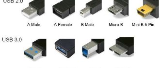
Connecting front panel USB to motherboard
First, we find the USB connector on the motherboard, usually it is located at the bottom of the motherboard and is labeled F_USB or USB. Also on each wire connector (Fig. 4.0) you can read its value, which can be +5V (or VCC or Power), D+, D – and GND.
Figure No. 4.0. USB polarity.
Next, you just need to install each of the wires (+5V, D+, D – and GND) to the right place on the motherboard, as shown in Fig. 4.2.
Figure No. 4.1. Connect USB 2.0 front panel to motherboard.
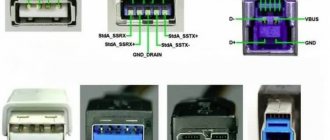
Figure No. 4.2. Connect USB 3.0 front panel to motherboard.
Figure No. 4.3. Connecting USB 2.0 to the motherboard.
ATX 20, 20+4, 24
Main 24-pin power connector and 20+4 pin power connector
If the video cards do not have enough power received through the PCI-Express connector, then use an additional 6-pin cable from the power supply. The additional power connector for PCI-Express video cards is similar to the additional power connector for the processor.
ATX 20 pin pinout
Conclusion- Name
- Description
- Color
| 1 | +3.3v | +3.3v | Orange |
| 2 | +3.3v | +3.3v | Orange |
| 3 | GND | (Housing, Common wire) | Black |
| 4 | +5v | +5v | Red |
| 5 | GND | (Housing, Common wire) | Black |
| 6 | +5v | +5v | Red |
| 7 | GND | (Housing, Common wire) | Black |
| 8 | PowerGood | Power supply ready signal | Grey |
| 9 | +5v Standby | +5v, Make-up in Standby mode | Lilac (Purple) |
| 10 | +12v | +12v | Yellow |
| 11 | +3.3v | +3.3v | Orange |
| 12 | -12v | -12v | Blue |
| 13 | GND | (Housing, Common wire) | Black |
| 14 | Power ON | Starting the power supply. | Green |
| 15 | GND | (Housing, Common wire) | Black |
| 16 | GND | (Housing, Common wire) | Black |
| 17 | GND | (Housing, Common wire) | Black |
| 18 | -5v | -5v | White |
| 19 | +5v | +5v | Red |
| 20 | +5v | +5v | Red |
style="width: 100%; color: black; height: 1px; background-color:gray;">
FLOPPY
The FLOPPY connector, used to power a floppy disk drive (FMD), is also obsolete, but unlike Molex, it is practically not used. Therefore, as a rule, new power supplies do not have it. Nevertheless, we present its pinout.
| FLOPPY connector pin assignments | ||
| Contact | Signal | Wire color |
| 1 | +5 V | red |
| 2 | general | black |
| 3 | general | black |
| 4 | +12 V | yellow |
Since float drives are still used on outdated computer models, as noted above, there are MOLEX/FLOPPY adapters that can be purchased in addition, or even found in the box with a new power supply.
So we figured out what connectors are equipped with ATX power supplies, and we also know the pinout of each of them. Now we can independently select a suitable power supply, and, if necessary, we can find the voltages that interest us on its connectors.
Filtration
The first thing the power supply does with mains electricity is not rectification or reduction, but equalization of the input voltage. Since our homes, offices and businesses have many electrical devices and appliances that constantly turn on and off, as well as emitting electromagnetic interference, alternating current in the network is often “lumpy” and with random surges and drops (the frequency is also not constant). Not only does this make it difficult for the power supply to carry out conversions, but it can damage some of the components inside it.
Our power supply has two stages of so-called input filters (transient filter), the first of which is built directly at the input using three capacitors. It performs a role similar to that of a speed bump on the road - only instead of speed, this filter dampens sudden surges in input voltage.
Photo source techspot.com
The second filter stage is more complex, but essentially does the same thing.
The yellow bricks are again capacitors, but the green rings wrapped in copper wire are inductive coils (although when used in this way they are usually called chokes). The coils accumulate electrical energy in a magnetic field, but the energy is not lost and is smoothly returned due to self-induction. Thus, a suddenly appearing high pulse (jump) is absorbed by the magnetic field of the inductor in order to give an even voltage at the output without any jumps.
The two small blue disks are another representative of the capacitor variety, and just below them (green, with long legs covered with black insulators) is a metal oxide varistor (MOV). They are also used to protect against input voltage surges. You can read more about the different types of input filters here.
Photo source techspot.com
From this power supply unit you can often determine how much the manufacturer has saved, or what budget class the device belongs to. Cheaper ones will have simplified input filtering, and the cheapest ones will not have it at all (avoid these!).
Now that the tension has been leveled and combed, he is allowed to move on - in fact, to transformation.
About the cross-section of wires coming out of the computer power supply
Although the currents that the power supply can supply to the load amount to tens of amperes, the cross-section of the output conductors, as a rule, is only 0.5 mm2, which allows current transmission through one conductor of up to 3 A. You can find out more about the load capacity of the wires from the article “On choosing a wire cross-section for electrical wiring.” However, all wires of the same color are soldered to one point on the printed circuit board, and if a block or module in a computer consumes more than 3 A of current, voltage is supplied through the connector along several wires connected in parallel. For example, voltage +3.3 V and +5 V is supplied to the motherboard via four wires. This ensures that up to 12 A of current is supplied to the motherboard.
- Color marking of PSU ATX
- ATX power supply repair
- BP ATX load block
Connecting the front panel to the motherboard
In this article, you will learn how to connect the power switch, reset switch and LEDs, as well as audio and USB ports to the motherboard. Before attempting to connect them, it is very important to know the location and polarity of the connection. To do this, you need to find diagrams in your motherboard manual that will tell you exactly where each set of pins is on the motherboard, or use the information in this article.
Installing an additional video card connector in the computer's power supply
Sometimes there are seemingly hopeless situations. For example, you bought a modern video card and decided to install it in your computer. There is the necessary slot on the motherboard for installing a video card, but there is no suitable connector on the wires for additional power supply to the video card coming from the power supply. You can buy an adapter, replace the entire power supply, or you can independently install an additional connector on the power supply to power the video card. This is a simple task, the main thing is to have a suitable connector, it can be taken from a faulty power supply.
First you need to prepare the wires coming from the connectors for the offset connection, as shown in the photo. An additional connector for powering the video card can be connected to the wires going, for example, from the power supply to drive A. You can also connect to any other wires of the desired color, but in such a way that there is enough length to connect the video card, and preferably nothing to them was no longer connected. The black wires (common) of the additional connector for powering the video card are connected to the black wire, and the yellow wires (+12 V), respectively, to the yellow wire.
The wires coming from the additional connector for powering the video card are tightly wrapped with at least three turns around the wire to which they are connected. If possible, it is better to solder the connections with a soldering iron. But even without soldering, in this case the contact will be quite reliable.
The work of installing an additional connector for powering the video card is completed by isolating the connection point, several turns, and you can connect the video card to the power supply. Due to the fact that the twisting points are located at a distance from each other, there is no need to isolate each twist separately. It is enough to cover only the area where the wires are exposed with insulation.
Connecting front panel USB to motherboard
First, we find the USB connector on the motherboard, usually it is located at the bottom of the motherboard and is labeled F_USB or USB. Also on each wire connector (Fig. 4.0) you can read its value, which can be +5V (or VCC or Power), D+, D – and GND.
Figure No. 4.0. USB polarity.
Next, you just need to install each of the wires (+5V, D+, D – and GND) to the right place on the motherboard, as shown in Fig. 4.2.
Figure No. 4.1. Connect USB 2.0 front panel to motherboard. Figure No. 4.2. Connect USB 3.0 front panel to motherboard. Figure No. 4.3. Connecting USB 2.0 to the motherboard.